2AWAA-RS7Thermal Imager
ZHEJIANG DALI TECHNOLOGY CO., LTD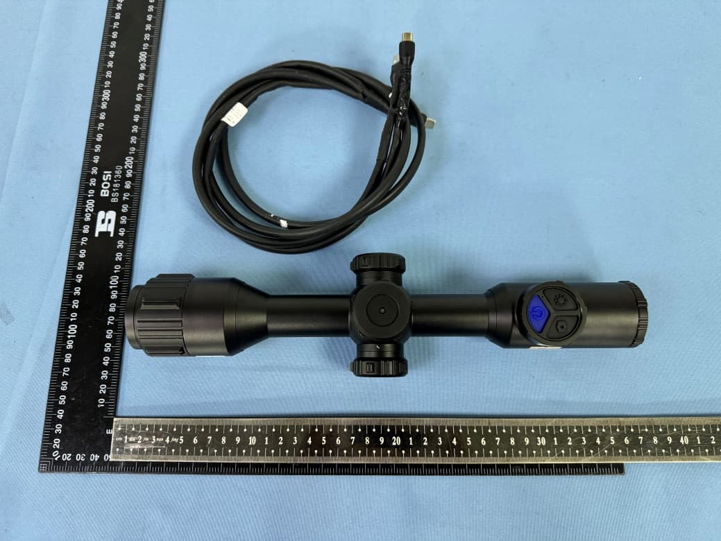
Click to zoom
Application Details
- Equipment Class
- DTS - Digital Transmission System
- Date of Grant
- Aug 01, 2024
- Application Purpose
- Original Equipment
- Date of Application
- Aug 01, 2024
- Equipment Note
- Thermal Imager
- Frequency Range
- 2412.00000000 - 2462.00000000
- Country
- China
Documents & Files
Document Text
Text extracted from the exhibit documents filed with the FCC. Open a document above to read the original.
Users Manual
series series NO. ButtonsFunction Power Photo Palette Knob Operation Focus Ring Interface External Battery Compartment Eyepiece Diopter Adjustment Lens cap Eye mask · short press: standby/wake-up Dead Spots menu: dead spot repair · long press: power · Short press: capture picture, and exit video recording · Long press: turn on the video recording · Short press: palette switching · Long press: manual image uniformity correction · Short press: 1X/2X/4X/8X fast zoom In menu mode: function conrmation · Long press: enter/exit user menu · Rotate: E-zoom 1.0~8.0x In menu mode: left/right switching and value addition/subtraction Manually adjusting image clarity Type-C interface, used for charging, external power supply, data transmission, system upgrade, and analog video output Can be powered by external battery, battery type CR123A Eyepiece diopter adjustment Lens protection Buffering and shading for better viewing 1 2 3 4 5 6 7 8 9 10 Power ·Short press: standby/wake-up, on/off eyepiece display. ·Long press: on/off device. Photo ·Short press: take photos and exit the video recording. ·Long press: turn on the video recording. Palette ·Short press: color palette switching among White hot, Black hot, Emerald, Iron hot, Red hot and Green. ·Long press: manual image uniformity correction, can be performed manually to refresh a clear image. Knob ·Short press: 1X/2X/4X/8X fast zoom in image. ·Long press: enter/exit user menu. ·Rotate: 1.0~8.0x zoom in. Single step 0.1x zoom for ne on target image. Capacity Palette Group Zoom WiFi System time Battery series Horizontal angle value Azimuth Pitch angle value series Knob Instruction ·Short press: function conrmation. ·Long press: return. ·Left/right switching and value addition/subtraction. series 4.1 Functions menu WiFi:off/AP/STA AP mode: Download the client program "IR-TRACKER V", install and run the mobile client program, and for the rst time in use, nd the instrument hot-spot "XXX_XXXXX" (WiFi name is "model serial number") in the mobile WiFi, with an initial password of "12345678". After successful connection, open the mobile "IR-TRACKER V" software, click on the software "Connect" to see the image, and use the mobile client software to achieve functions such as taking photos, recording, playback, and storage of the image. After connecting, the WiFi name and password can be customized on the client side. Click "Setting" on the homepage to enter the settings, select "WIFI settings", enter the desired WiFi name and password, click "Conrm the changes", and the STA mode setting is completed. STA mode: You need to rst connect to the client in AP mode. Click "Setting" on the homepage to enter the settings, select "Router settings", enter the WiFi name and password you want to connect to, click "Conrm the changes", and the STA mode setting is completed. Select STA mode for local WiFi to automatically connect to the network. Note: Turning on WIFI for a long time will increase the power consumption of the device, resulting in shorter standby time, please turn off this function when not in use. series OSD:on/off Display and Hidden of Status Bar. RAV:on/off Enable RAV function. When the impact occurs, the local recording will automatically start, and a pre-recorded video of 10 seconds before the impact will be synthesized into the recording le. Screen Brightness:1/2/3/4/5 Support 5-level eyepiece display screen brightness adjustment. Distance estimate Automatically displays the estimated distance to a specic target size object on the scale. Hot-spot tracking:on/off When turned on, the main interface will appear to automatically track the cursor to display the highest temperature point on the screen. Picture in Picture:off/Top/Bottom It can be displayed in two xed positions, top and bottom, and the center area will be enlarged twice. Enhance:0~15 Enhance the clarity of the image by up to 15 levels, the factory default is 5 level. Auto NUC:on/off When turned on, the device automatically zeroing for image refresh; When turned off, the device will no longer automatically refresh images. You can manually refresh images by long pressing the button "Palette". th series 4.2 System setting Language:English/Russian/German Three languages are optional. System information Displays information such as device model/software version. Formatting The built-in memory card can be formatted, and a prompt will appear at the top after successful formatting. Please operate with caution. Upgrade Version upgrades are available. The operation of version upgrade is as follows: Preparation: Download the version upgrade program le through PC (for details, please contact the manufacturer's after-sales technical support), and copy the ".upp" upgrade program to the root directory of the local storage space of the device. Device upgrade: Click the function in the device and select upgrade. After the upgrade is completed, press and hold the button"power " to turn off the device, and then turn on the device again to restart, the upgrade will be completed. Save:on/off When turned on, the recording will save the audio. Compass calibration After entering the compass calibration, rotate the device according to the prompts to correct the electronic compass. Sleep:0/5/30/60 The optional automatic sleep time is 0min/5min/30min/60min. If there is no operation during this time period, the eyepiece will be automatically turned off. The device will be in low-power standby mode, and press any button to restore. 4.3 Zeroing (Calibration) Knob ·Short press: function conrmation. ·Rotate: Left/right switching and value addition/subtraction. series series Group:1/2/3/4/5 Five sets of user-dened parameters for riescope calibration. Cursor Type:0~10 Ten cursor types are available, default "0" off. Color: White/Red/Green/Yellow Four cursor colors are available. Freeze: on/off Freeze the image. Zoom in:1X/2X/4X/8X 1x/2x/4x/8x centered on the cursors. Left/Right:[-360,360] Moves the cursor left/right o…
Text truncated - open the document above for the full version.
Attestation Statements
ZHEJIANG DALI TECHNOLOGY CO., LTD * the applicant must designate a contact located in the United States for purposes of acting as the applicant’s agent for service of process, regardless of whether the applicant is a domestic or foreign entity. An applicant located in the United States may designate itself as the agent for service of process. U.S. Agent Designation for Service of Process - Certification Attestation Letter July 9, 2024 Nemko North America, Inc. 303 River Road Ottawa K1V 1H2 Canada ATTN.: Reviewing Engineer FCC ID: 2AWAA-RS7 Per section 2.911(d)(7) of the FCC rules, ZHEJIANG DALI TECHNOLOGY CO., LTD (“the applicant”) , FRN: 0029512258 certifies that the equipment for which authorization is sought is designated to the following U.S. Designated agent* for service of process: Company Name: EMCTEK Physical U.S. Company Address: 11788 Big Canyon Ln, San Diego, CA 92131 USA Agent name: Fang Liu Agent Email Address: [email protected] FRN: 0033401829 The above contact person accepts the obligation for service of process. The applicant accepts to maintain an agent for no less than one year after the grantee has terminated all marketing and importation or the conclusion of any Commission-related proceeding involving the equipment. Applicant Signed: Designated Agent Signed: (Required, if different to Applicant): Signed: Signed: Printed name: Shi changbing Printed name: Fang Liu Title: / Title: / Company Name: ZHEJIANG DALI TECHNOLOGY CO., LTD Company Name: EMCTEK Date: July 9, 2024 Date: June 13, 2024 FRN Code: 0029512258 FRN Code: 0033401829
Attestation Statements
ZHEJIANG DALI TECHNOLOGY CO., LTD Covered Equipment Certification Attestation Letter 7/9/2024 Nemko North America, Inc. 303 River Road Ottawa K1V 1H2 Canada ATTN.: Reviewing Engineer FCC ID: 2AWAA-RS7 ZHEJIANG DALI TECHNOLOGY CO., LTD (“the applicant”) certifies that the equipment for which authorization is sought is not “covered” equipment prohibited from receiving an equipment authorization pursuant to section 2.903 of the FCC rules. Note: If the equipment for which the applicant seeks authorization is produced by any of the entities identified on the current Covered List , the applicant should include an explanation on why the equipment is not “covered” equipment. ZHEJIANG DALI TECHNOLOGY CO., LTD (“the applicant”) certifies that, as of the date of the filing of the application, the applicant is not identified on the Covered List as an entity producing “covered” equipment. Signature: Name: Shi changbing Company: ZHEJIANG DALI TECHNOLOGY CO., LTD Address: NO639 Binkang Road, Hangzhou, P.R.CHINA 310053 Phone: 8657186483758 Fax: 8657186483758 E-Mail: [email protected]
Cover Letter(s)
ZHEJIANG DALI TECHNOLOGY CO., LTD Date: 2024.07.09 FCC ID: 2AWAA-RS7 Dear Sir/Madam, We, ZHEJIANG DALI TECHNOLOGY CO., LTD Hereby declares the following statement for Federal Communications Commission, All these models are identical in the same in structure/host enclosure, internal circuitry/PCB components, hardware/software, The only difference is optical lenses. Product name: Thermal Imager Model no.: RS750-640, RS735-384, RS735-640, RS750-384 See the following table for detailed optical lenses configuration: RS750-640, RS750-384 optical focus: 50mm RS735-640, RS735-384 optical focus: 35mm RS750-640 resolution ratio: 640 PPI RS735-640 resolution ratio: 640 PPI RS735-384 resolution ratio: 384 PPI RS750-384 resolution ratio: 384 PPI Sincerely, Signature: Name: Shi changbing Phone: 8657186483758 Fax: 8657186483758 E-Mail: [email protected]
Cover Letter(s)
ZHEJIANG DALI TECHNOLOGY CO., LTD Date: 2024.07.09 Equipment Autorisation Division Federal Communications Commission 7435 Oakland Mills Road Columbia, MD 21046 FCC ID:_2AWAA-RS7___ Product Name:__Thermal Imager ________ Request for Confidentiality Pursuant to Sections 0.457 and 0.459 of the commissions rules, we hereby request that the following documents be held confidential: (List here the documents for which you are seeking confidentiality – for example ...) • Schematics • Block Diagram • Operation Description These materials contain trade secrets and proprietary information and are not customarily released to the public. The public disclosure of this information might be harmful to the company and provide unjustified benefits to our competitors. Signature: Name: Shi changbing Company: ZHEJIANG DALI TECHNOLOGY CO., LTD Address: NO639 Binkang Road, Hangzhou, P.R.CHINA 310053 Phone: 8657186483758 Fax: 8657186483758 E-Mail: [email protected]
Cover Letter(s)
ZHEJIANG DALI TECHNOLOGY CO., LTD \\192.168.1.200\sz-ctc\09_工程部\RF实验室\2024年案件\4月\CTC240423-003 通鉴 RS7 RED & FCC ID\1.资料\1.3 申请资料 \Letter\POA_Letter_140225.docx Equipment Autorisation Division Federal Communications Commission 7435 Oakland Mills Road Columbia, MD 21046 Date: 2024.07.09 SUBJECT: FCC Application for FCC ID: 2AWAA-RS7 To Whom It May Concern: We, the undersigned, hereby authorize _ Titto Zhao _ at _CTC Laboratories, Inc. on our behalf, to apply to the Federal Communications Commission on our equipment. Any and all acts carried out by _ Titto Zhao _ on our behalf shall have the same effect as acts of our own. This is to advise that we are in full compliance with the Anti- Drug Abuse Act. We, the applicant, are not subject to a denial of federal benefits pursuant to Section 5301 of the Anti-Drug Act of 1988, 21 USC853a, and no party to the application is subject to a denial of federal benefits pursuant to that section. Regards, Signature: Name: Shi changbing Company: ZHEJIANG DALI TECHNOLOGY CO., LTD Address: NO639 Binkang Road, Hangzhou, P.R.CHINA 310053 Phone: 8657186483758 Fax: 8657186483758 E-Mail: [email protected]
Cover Letter(s)
ZHEJIANG DALI TECHNOLOGY CO., LTD Date: 2024.07.09 FCC ID: 2AWAA-RS7 Dear Sir/Madam, We, ZHEJIANG DALI TECHNOLOGY CO., LTD Hereby declares the Product name: Thermal Imager, Model no.: RS750-640, RS735-384, RS735-640, RS750-384, Have done SDOC certification. Sincerely, Signature: Name: Shi changbing Company: ZHEJIANG DALI TECHNOLOGY CO., LTD Address: NO639 Binkang Road, Hangzhou, P.R.CHINA 310053 Phone: 8657186483758 Fax: 8657186483758 E-Mail: [email protected]
External Photos
CTC Laboratories, Inc. Room 101 Building B, No. 7, Lanqing 1st Road, Luhu Community, Guanhu Subdistrict, Longhua District, Shenzhen, Guangdong, China Tel: +86-755- 27521059 Fax: +86-755- 27521011 Http://www.sz-ctc.org.cn Page 1 of 5 External Photographs Page 2 of 5 Page 3 of 5 Page 4 of 5 Page 5 of 5
ID Label/Location Info
CTC Laboratories, Inc. 1-2/F., Building 2, Jiaquan Building, Guanlan High-Tech Park, Shenzhen, Guangdong, China Tel: +86-755- 27521059 Fax: +86-755- 27521011 Http://www.sz-ctc.org.cn Page 1 of 1 Label Label Location 1.
Internal Photos
CTC Laboratories, Inc. Room 101 Building B, No. 7, Lanqing 1st Road, Luhu Community, Guanhu Subdistrict, Longhua District, Shenzhen, Guangdong, China Tel: +86-755- 27521059 Fax: +86-755- 27521011 Http://www.sz-ctc.org.cn Page 1 of 12 Internal Photographs Page 2 of 12 Page 3 of 12 Page 4 of 12 Page 5 of 12 Page 6 of 12
Internal Photos
Page 7 of 12 Page 8 of 12 7cm Page 9 of 12 Page 10 of 12 WIFI Ant. Page 11 of 12 Page 12 of 12
RF Exposure Info
CTC Laboratories, Inc. Room 101 Building B, No. 7, Lanqing 1st Road, Luhu Community, Guanhu Subdistrict, Longhua District, Shenzhen, Guangdong, China Tel: +86-755- 27521059 Fax: +86-755- 27521011 Http://www.sz-ctc.org.cn CTC Laboratories, Inc. Room 101 Building B, No. 7, Lanqing 1st Road, Luhu Community, Guanhu Subdistrict, Longhua District, Shenzhen, Guangdong, China Tel.: (86)755-27521059 Fax: (86)755-27521011 Http://www.sz-ctc.org.cn For anti-fake verification, please visit the official website of Certification and Accreditation Administration of the People’s Republic of China : yz.cnca.cn RF Exposure Evaluation FCC ID: 2AWAA-RS7 According to KDB447498 D01 General RF Exposure Guidance v06 EUT Specification Product Name: Thermal Imager Trade Mark: / Model/Type reference: RS750-640 Listed Model(s): RS735-384, RS735-640, RS750-384 Model Different: All these models are identical in the same PCB, layout and electrical circuit, The only difference is optical lenses. Frequency band (Operating): 2412MHz ~ 2462MHz Device category Portable (<5mm separation) Mobile (>20cm separation) Fixed (>30mm separation) Others ___ Antenna diversity Single antenna Multiple antennas TX diversity RX diversity TX/RX diversity Antenna gain (Max) 4.97dBi Evaluation applied MPE Evaluation SAR Evaluation Page 2 of 4 Report No.: CTC20241053E03 CTC Laboratories, Inc. Room 101 Building B, No. 7, Lanqing 1st Road, Luhu Community, Guanhu Subdistrict, Longhua District, Shenzhen, Guangdong, China Tel.: (86)755-27521059 Fax: (86)755-27521011 Http://www.sz-ctc.org.cn For anti-fake verification, please visit the official website of Certification and Accreditation Administration of the People’s Republic of China : yz.cnca.cn Limit: According to the 4.3 General SAR Test Exclusion Guidelines of KDB 447489 D01 a) For 100 MHz to 6 GHz and test separation distances ≤ 50 mm, the 1-g and 10-g SAR test exclusion thresholds are determined by the following: [(max. power of channel, including tune-up tolerance, mW) / (min. test separation distance, mm)] · [√f (GHz) ] ≤ 3.0 for 1-g SAR, and ≤ 7.5 for 10-g extremity SAR Where -f (GHz) is the RF channel transmit frequency in GHz -Power and distance are rounded to the nearest mW and mm before calculation -The result is rounded to one decimal place for comparison -The values 3.0 and 7.5 are referred to as numeric thresholds in step b) below The test exclusions are applicable only when the minimum test separation distance is ≤ 50 mm, and for transmission frequencies between 100 MHz and 6 GHz. When the minimum test separation distance is < 5 mm, a distance of 5 mm according to 4.1 f) is applied to determine SAR test exclusion. b) For 100 MHz to 6 GHz and test separation distances > 50 mm, the 1-g and 10-g SAR test exclusion thresholds are determined by the following (also illustrated in Appendix B): 1) {[Power allowed at numeric threshold for 50 mm in step a)] + [(test separation distance – 50 mm)·(f (MHz) /150)]} mW, for 100 MHz to 1500 MHz 2) {[Power allowed at numeric threshold for 50 mm in step a)] + [(test separation distance – 50 mm)·10]} mW, for > 1500 MHz and ≤ 6 GHz Page 3 of 4 Report No.: CTC20241053E03 CTC Laboratories, Inc. Room 101 Building B, No. 7, Lanqing 1st Road, Luhu Community, Guanhu Subdistrict, Longhua District, Shenzhen, Guangdong, China Tel.: (86)755-27521059 Fax: (86)755-27521011 Http://www.sz-ctc.org.cn For anti-fake verification, please visit the official website of Certification and Accreditation Administration of the People’s Republic of China : yz.cnca.cn Product Description: The product is evaluated in the manual, it can be mounted on the rifle and has two modes of use. Mode 1: The product is mounted on the rifle and carried on the back. The product is in sleep mode. Mode 2: When the product is sighted in, the wireless function of the product is turned on. The minimum distance from the head to the radiation element is 70mm. When the product is in use, the limb holds the rifle. The minimum distance from the extremity to the radiation element is 30mm. Therefore, the product is in Mode 2 and Mode 3 when RF exposure is evaluated and calculated. The following figure shows the shortest distance from the antenna to the head when the wireless function is on. The following figure shows the shortest distance from the antenna to the extremity when the wireless function is on. 7cm Antenna position Page 4 of 4 Report No.: CTC20241053E03 CTC Laboratories, Inc. Room 101 Building B, No. 7, Lanqing 1st Road, Luhu Community, Guanhu Subdistrict, Longhua District, Shenzhen, Guangdong, China Tel.: (86)755-27521059 Fax: (86)755-27521011 Http://www.sz-ctc.org.cn For anti-fake verification, please visit the official website of Certification and Accreditation Administration of the People’s Republic of China : yz.cnca.cn Measurement Result Extremity exposure @ 30mm Worst Mode Frequency (GHz) Maximum Power (dBm) Max. Tune up Power (dBm) EIRP (dBm) EIRP (mW) Calculation result Limit (for 10-g SAR exclusion thresholds) Verdict 802.11b 2.437 15.50 16.00 20.97 125.03 6.5 7.5 Compiles Head exposure @ 70mm Worst Mode Frequency (GHz) Maximum Power (dBm) Max. Tune up Power (dBm) EIRP (dBm) EIRP (mW) Power allowed threshold for 50 mm (mW) Limit (for 1-g SAR exclusion thresholds) (mW) Verdict 802.11b 2.437 15.50 16.00 20.97 125.03 96 296 Compiles Calculation: Power allowed at numeric threshold for 50 mm in step a: 3.0*(min. test separation distance, mm)/ √f (GHz) = [3.0*50]/√2.437=96mW 10-g SAR test exclusion thresholds: {[Power allowed at numeric threshold for 50 mm in step a)] + [(test separation distance – 50 mm)·10]} mW=96mW+[ (70-50)*10mW]=296mW EIRP (mW) ≤ for 1-g SAR exclusion thresholds (mW) 125.03 ≤ 296 Calculation result: Compiles Note: 1. Calculate by Worst-case mode. 2. Max. Tune up Power by Manufacturer's Declaration, and Max. Tune Up Power is used to calculate. 3. The extremity is calculated at a distance of 55.9mm, the head is calculated at a distance of 70mm (by the manufacturer). 4.…
Text truncated - open the document above for the full version.
Test Report
- 1 - 产 品 技 术 规 格 书 SPECIFICATION 产品型号 PART NO: A36 Manufacturer: ZHEJIANG DALI TECHNOLOGY CO., LTD Address: NO639 Binkang Road, Hangzhou, P.R.CHINA, 310053 -2- 目录 Tableofcontents 规格书版本更改记录Versionrejiggertrackrecord..............................3 1.概述Introduction..................................................................4 2.型号PartNumber...............................................................4 3.外型尺寸及测试板焊盘尺寸Dimensions.....................4~5 4.测试电路和匹配电路EvaluationBoardandMatchingCircuits............5 5.电气性能ElectricalCharacteristics..........................................6 6.特性曲线Characteristiccurve...................................................6 7.方向图RadiationPattern...................................................7~8 8.可靠性试验后允许误差PostDependabilityTolerance...............9 9.可靠性试验DependabilityTest..........................................9~10 10.回流焊温度ReflowSolderingStandardCondition.....................10 11.包装尺寸PackagingandDimensions....................................11 -3- 产品规格书版本更改记录 Versionrejiggertrackrecord 版本号 Version 更改记录Rejigger 拟制 Prepared 批准 Approve 日期 Date 备注: 1、更改产品电性能指标时,版本号需更换(V1.0换为V2.0、V3.0......); 2、更改产品测试方法(包括可靠性测试条件),或更改使用条件时,当前版本号加系列(V1.0 换为V1.1、V1.2......)。 -4- 产品尺寸/Size:5.2×2.0×1.2 1.概述INTRODUCTION 微波多层陶瓷天线LA系列产品设计用于WLAN、WiFi、蓝牙、PHS,手机 多频天线,FM等小体积SMD片式设计。 MicrowaveMulti-LayerCeramicAntennaLAseriesaredesignedtobeused inWLAN、WiFi、Bluetooth、PHS、Multiple-bandMobilephoneantenna,FM,etcand compactsizeSMDchipdesign. 2.型号PartNumber LA52H2450–A36 3.外型尺寸及测试板焊盘尺寸Dimensions(Unit:mm) 天线频率/AntennaFrequency:2450MHz 产品设计结构H型/ViaDesignSeries 多层结构天线/Multi-layerAntenna 产品名称,编号A36/ProudctName:A36 -5- 4.测试电路和匹配电路EvaluationBoardandMatchingCircuits 90 50 Unit:mm 4.3nH 1.5pF -6- 5.电气性能ElectricalCharacteristics 6.特性曲线Characteristiccurve No. Item(项目)Specifications(特性) 5.1WorkingCentralFrequency中心工作频率2450MHz 5.2BandWidth通带宽度100MHztyp. 5.3PeakGain峰值增益4.97dBi 5.4V.S.W.R驻波比≤2.0 5.5 Polarization极化方式 Linear线性 5.6 AzimuthBeamwidth方位角 Omni-directional全向 5.7 Impedance阻抗 50Ω -7- 7.方向图及效率RadiationPattern&Efficiency coordinates: X-ZPlanePlane Y-ZPlane -8- X-YPlane 3DRadiationPattern Frequency (MHz) 240024502500 Avg.Gain (dBi) -0.75-0.79-0.88 PeckGain (dBi) 4.524.974.85 Efficiency (%) 70.271.171.2
Test Report
CTC Laboratories, Inc. Room 101 Building B, No. 7, Lanqing 1st Road, Luhu Community, Guanhu Subdistrict, Longhua District, Shenzhen, Guangdong, China Tel: +86-755- 27521059 Fax: +86-755- 27521011 Http://www.sz-ctc.org.cn TEST REPORT Report No. ··························: CTC20241053E02 FCC ID································: 2AWAA-RS7 Applicant····························: ZHEJIANG DALI TECHNOLOGY CO., LT D Address·······························: NO639 Binkang Road, Hangzhou, P.R.CHINA, 310053 Manufacturer························: ZHEJIANG DALI TECHNOLOGY CO., LTD Address·······························: NO639 Binkang Road, Hangzhou, P.R.CHINA, 310053 Product Name······················: Thermal Imager Trade Mark···························: / Model/Type reference·············: RS750-640 Listed Model(s) ····················: RS735-384, RS735-640, RS750-384 Standard·····························: FCC CFR Title 47 Part 15 Subpart C Section 15.247 Date of receipt of test sample...: Apr. 23, 2024 Date of testing.......................: Apr. 24, 2024 ~ May. 30, 2024 Date of issue.........................: May. 31, 2024 Result.................................: PASS Compiled by: (Printed name+signature) Terry Su Supervised by: (Printed name+signature) Eric Zhang Approved by: (Printed name+signature) Totti Zhao Testing Laboratory Name......: CTC Laboratories, Inc. Address...............................: Room 101 Building B, No. 7, Lanqing 1st Road, Luhu Community, Guanhu Subdistrict, Longhua District, Shenzhen, Guangdong, China This test report may be duplicated completely for legal use with the approval of the applicant. It should not be reproduced except in full, without the written approval of our laboratory. The client should not use it to claim product endorsement by CTC. The test results in the report only apply to the tested sample. The test report shall be invalid without all the signatures of testing engineers, reviewer and approver. Any objections must be raised to CTC within 15 days since the date when the report is received. It will not be taken into consideration beyond this limit. The test report merely correspond to the test sample. Page 2 of 80 Report No.: CTC20241053E02 CTC Laboratories, Inc. Room 101 Building B, No. 7, Lanqing 1st Road, Luhu Community, Guanhu Subdistrict, Longhua District, Shenzhen, Guangdong, China Tel.: (86)755-27521059 Fax: (86)755-27521011 Http://www.sz-ctc.org.cn For anti-fake verification, please visit the official website of Certification and Accreditation Administration of the People’s Republic of China : yz.cnca.cn Table of Contents Page 1. TEST SUMMARY ............................................................................................................................................ 3 1.1. T EST STANDARDS ................................................................................................................................................. 3 1.2. R EPORT VERSION ................................................................................................................................................. 3 1.3. T EST DESCRIPTION ............................................................................................................................................... 4 1.4. T EST FACILITY ...................................................................................................................................................... 5 1.5. M EASUREMENT UNCERTAINTY ............................................................................................................................... 5 1.6. E NVIRONMENTAL CONDITIONS ............................................................................................................................... 6 2. GENERAL INFORMATION ............................................................................................................................... 7 2.1. C LIENT INFORMATION ........................................................................................................................................... 7 2.2. G ENERAL DESCRIPTION OF EUT ............................................................................................................................. 7 2.3. A CCESSORY EQUIPMENT INFORMATION .................................................................................................................... 8 2.4. O PERATION S TAT E ................................................................................................................................................ 9 2.5. M EASUREMENT INSTRUMENTS LIST ...................................................................................................................... 10 3. TEST ITEM AND RESULTS .............................................................................................................................. 12 3.1. C ONDUCTED EMISSION ....................................................................................................................................... 12 3.2. R ADIATED EMISSION ........................................................................................................................................... 15 3.3. B AND EDGE EMISSIONS (RADIATED) ...................................................................................................................... 37 3.4. B AND EDGE AND SPURIOUS EMISSIONS (CONDUCTED) ............................................................................................. 50 3.5. DTS BANDWIDTH .............................................................................................................................................. 64 3.6. M AXIMUM CONDUCTED OUTPUT POWER .............................................................................................................. 69 3.7. P OWER SPECTRAL DENSITY ........................................................................................................................…
Text truncated - open the document above for the full version.
Test Report
Page 73 of 80 Report No.: CTC20241053E02 CTC Laboratories, Inc. Room 101 Building B, No. 7, Lanqing 1st Road, Luhu Community, Guanhu Subdistrict, Longhua District, Shenzhen, Guangdong, China Tel.: (86)755-27521059 Fax: (86)755-27521011 Http://www.sz-ctc.org.cn For anti-fake verification, please visit the official website of Certification and Accreditation Administration of the People’s Republic of China : yz.cnca.cn 802.11b_2412 802.11b_2437 802.11b_2462 Page 74 of 80 Report No.: CTC20241053E02 CTC Laboratories, Inc. Room 101 Building B, No. 7, Lanqing 1st Road, Luhu Community, Guanhu Subdistrict, Longhua District, Shenzhen, Guangdong, China Tel.: (86)755-27521059 Fax: (86)755-27521011 Http://www.sz-ctc.org.cn For anti-fake verification, please visit the official website of Certification and Accreditation Administration of the People’s Republic of China : yz.cnca.cn 802.11g_2412 802.11g_2437 802.11g_2462 Page 75 of 80 Report No.: CTC20241053E02 CTC Laboratories, Inc. Room 101 Building B, No. 7, Lanqing 1st Road, Luhu Community, Guanhu Subdistrict, Longhua District, Shenzhen, Guangdong, China Tel.: (86)755-27521059 Fax: (86)755-27521011 Http://www.sz-ctc.org.cn For anti-fake verification, please visit the official website of Certification and Accreditation Administration of the People’s Republic of China : yz.cnca.cn 802.11n(HT20)_2412 802.11n(HT20)_2437 802.11n(HT20)_2462 Page 76 of 80 Report No.: CTC20241053E02 CTC Laboratories, Inc. Room 101 Building B, No. 7, Lanqing 1st Road, Luhu Community, Guanhu Subdistrict, Longhua District, Shenzhen, Guangdong, China Tel.: (86)755-27521059 Fax: (86)755-27521011 Http://www.sz-ctc.org.cn For anti-fake verification, please visit the official website of Certification and Accreditation Administration of the People’s Republic of China : yz.cnca.cn 3.8. Duty Cycle Limit None, for report purposes only. Test Configuration Test Procedure 1. The EUT was directly connected to the spectrum analyzer and antenna output port as show in the block diagram above. 2. The EUT was directly connected to the Spectrum Analyzer and antenna output port as show in the block diagram above. The measurement according to section 10.2 of KDB 558074 D01 DTS Meas Guidance v05r02. 3. Spectrum Setting: Set analyzer center frequency to DTS channel center frequency. Set the span to 0Hz Set the RBW to 8MHz Set the VBW to 8MHz Detector: peak Sweep time: auto Allow trace to fully stabilize. Then use the peak marker function to determine the maximum amplitude level. Test Mode Please refer to the clause 2.4. Test Result Te s t Mode Frequency [MHz] Transmission Duration [ms] Transmission Period [ms] Duty Cycle [%] Duty Cycle Factor 1/T Minimum VBW [kHz] Final setting For VBW [kHz…
Text truncated - open the document above for the full version.
Contact Information
Applicant
shi changbing
Test Firm
CTC Laboratories, Inc.Totti Zhao
[email protected]+8675527521059
Technical Specifications
| # | Rule Parts | Frequency Range | Power Output |
|---|---|---|---|
| 1 | 15C | 2.41 GHz - 2.46 GHz | 35.50 mW |
Other Applications from ZHEJIANG DALI TECHNOLOGY CO., LTD
2AWAA-HRYXBSZ-F8
Sep 11, 2024Thermal Imaging Camera
Equipment Class
DTS - Digital Transmission System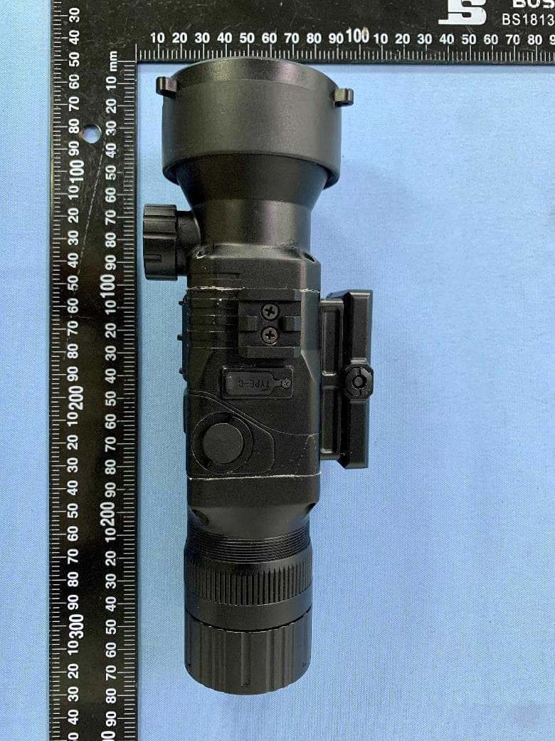
2AWAA-RS6
Sep 01, 2024Thermal Imager
Equipment Class
DTS - Digital Transmission System
2AWAA-MS735MH
Jan 09, 2024Thermal Imager
Equipment Class
DTS - Digital Transmission System
2AWAA-T12M
Jan 04, 2024Thermal Imaging Camera
Equipment Class
DTS - Digital Transmission System
2AWAA-MS715
Dec 12, 2022Thermal Imager
Equipment Class
DTS - Digital Transmission System