2AWAA-RS1Thermal Inaging Riflescopes
ZHEJIANG DALI TECHNOLOGY CO., LTDApplication Details
- Equipment Class
- DTS - Digital Transmission System
- Date of Grant
- May 06, 2020
- Application Purpose
- Original Equipment
- Date of Application
- Apr 29, 2020
- Equipment Note
- Thermal Inaging Riflescopes
- Frequency Range
- 2412.00000000 - 2462.00000000
- Country
- China
Documents & Files
Document Text
Text extracted from the exhibit documents filed with the FCC. Open a document above to read the original.
Users Manual
RS1 Scope Quick Start Appearance, button and composition Button and function description Power button Long press 3 seconds to switch on/off the thermal camera; After power on, short press power button to turn off eyepiece display, short press again to wake up the eyepiece. Digital zoom button Short press, X2、X3、X4 image digital zoom switch,Can zoom in and out on the target in real time; Long press 3 seconds, image manually calibration. Photo button Short press: photograph; Long press: start video recording, short press again to end the video recording. Menu knob Press the knob for 2 seconds to pop up the image menu, Switch the menu function by turning the knob, short press to confirm the function, long press the menu to exit. Main menu function description Color mode menu Press and hold the menu knob for 2 seconds. After popping up the menu, there are four color modes (black hot, white hot, red hot, iron red), turn the knob to select the color mode and short press the menu knob to confirm. Picture-in-picture menu Distance estimate Color mode switch Image Picture-in-picture WIFI Image calibration Cursor adjustment Hot spot tracking Brightness adjustment Contrast adjustment System settings Press and hold the menu knob for 2 seconds. After popping up the menu, turn the knob to select “on/off” and short press the menu knob to confirm. WIFI button Press and hold the menu knob for 2 seconds. After popping up the menu, turn the knob to select “on/off” WiFi function and short press the menu knob to confirm. If the WiFi logo appears at the top right of the main screen, it proves this function to be turned on normally. When the WiFi function of the scope is turned on, turn on the WiFi function of the mobile phone, search for the WiFi hotspot in the form of “WIFIV_xxxxxx”, and enter the password “12345678” to connect. After the connection is completed, open the mobile APP and click the connection. Image calibration menu Press and hold the menu knob for 2 seconds. After popping up the menu, turn the knob to select “on/off” auto calibration function and short press the menu knob to confirm. Cursor adjustment Press and hold the menu knob for 2 seconds. After popping up the menu, turn the knob to select”N/A/Standard/Ranging”, short press the menu knob to confirm. Then adjust the cursor position, turn the knob to select the “X/Y” coordinate, short press the menu knob to confirm, turn the knob to change the coordinate value, and short press the menu knob to confirm. Distance estimate Press and hold the menu knob for 2 seconds. After popping up the menu, turn the knob to select coordinate card size, short press the menu knob to confirm. Hot spot tracking Press and hold the menu knob for 2 seconds. After popping up the menu, turn the knob to select “on/off” hot spot tracking function and short press the menu knob to confirm. Brightness adjustment Press and hold the menu knob for 2 seconds. After popping up the menu, turn the knob to adjust brightness value (0~100), short press the menu knob to confirm. Contrast adjustment Press and hold the menu knob for 2 seconds. After popping up the menu, turn the knob to adjust contrast value (0~100), and short press the menu knob to confirm. System settings Press and hold the menu knob for 2 seconds. After popping up the menu, will appear the following submenu: 1. Language option,short press to select the function, turn the knob to select “Chinese/English” language option, and short press the menu knob to confirm. 2. Memory format options, short press to select the function, turn the knob to select “Yes/No” to conduct format operation, short press the menu knob to confirm. 3. Factory default option, short press to select the function, turn the knob to select “Yes/No” to conduct factory default operation, short press the menu knob to confirm. 4. Image enchance option, short press to select the function, turn the knob to adjust brightness value (0~60), short press the menu knob to confirm. 5. Manual dotting option, short press to select the function,will appear the cursor and its X and Y axis coordinates, turn the knob to select the "X/Y" coordinates, short press the knob to confirm, turn the knob to change the coordinate value, and short press the knob to confirm. After coincident with the coordinates of the bad pixel, short press the digital zoom button to conduct dotting (clear bad pixels) and save. 6. Low consumption option,short press to select the function, turn the knob to select “Yes/No”, short press the menu knob to confirm. Under low consumption mode, the functions of photographing, recording and WiFi cannot be used, which will increase the usage time. Eyepiece diopter adjustment According to individual vision, after starting up and seeing the image, turn the diopter knob to see the battery logo of the screen clearly, it proves the diopter adjustment finsihed. Lens focus After the device start-up and sees the image display, adjust the lens focus ring to a clear image (clear target contour). Charging, date interface When charging, unscrew the cover of the charging interface and insert the type-c charging connector (charging time is about 5 hours, charging voltage DC5V(1A/2A) Unscrew the cover of the charging port, connect to the computer, and copy the photo and video data files. Attention As the uncooled infrared scope uses very sensitive thermal sensors, so in any case (power on or power off), do not aim the lens at the strong radiation source (such as the sun, laser beam direct or reflection), otherwise it will cause permanent damage to the uncooled infrared thermal scope! Do not open the shell or modify it without permission. The maintenance can only be carried out by the authorized personnel of the company. Federal Communication Commission Interference Statement This equipment has been tested and found to comply with the limits for a Class B digital device, pursuant to Part 15 of the FCC Rules. These limits are designed to provide re…
Text truncated - open the document above for the full version.
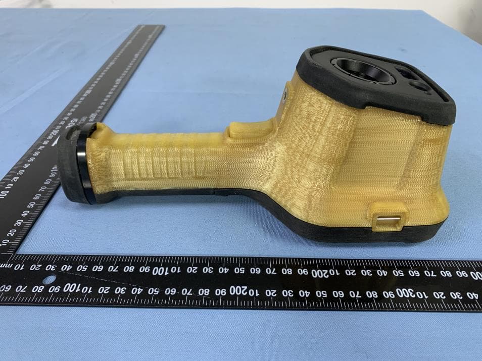
External Photos
CERPASS TECHNOLOGY (SUZHOU)CO., LTD Report No.: SEFI2004062 Cerpass Technology (Suzhou) Co., Ltd. Issued date : Apr. 16, 2020 Page No. : 1 of 3 EXTERNAL PHOTOGRAPHS OF EUT 1) EUT Photo 2) EUT Photo CERPASS TECHNOLOGY (SUZHOU)CO., LTD Report No.: SEFI2004062 Cerpass Technology (Suzhou) Co., Ltd. Issued date : Apr. 16, 2020 Page No. : 2 of 3 3) EUT Photo 4) EUT Photo CERPASS TECHNOLOGY (SUZHOU)CO., LTD Report No.: SEFI2004062 Cerpass Technology (Suzhou) Co., Ltd. Issued date : Apr. 16, 2020 Page No. : 3 of 3 5) EUT Photo
Internal Photos
CERPASS TECHNOLOGY CORP. Report No.: SEFI2004062 Cerpass Technology (Suzhou) Co., Ltd. Issued date : Apr. 16, 2020 Page No. : 1 of 8 INTERNAL PHOTOGRAPHS OF EUT 1) EUT Photo 2) EUT Photo CERPASS TECHNOLOGY CORP. Report No.: SEFI2004062 Cerpass Technology (Suzhou) Co., Ltd. Issued date : Apr. 16, 2020 Page No. : 2 of 8 3) EUT Photo 4) EUT Photo CERPASS TECHNOLOGY CORP. Report No.: SEFI2004062 Cerpass Technology (Suzhou) Co., Ltd. Issued date : Apr. 16, 2020 Page No. : 3 of 8 5) EUT Photo 6) EUT Photo CERPASS TECHNOLOGY CORP. Report No.: SEFI2004062 Cerpass Technology (Suzhou) Co., Ltd. Issued date : Apr. 16, 2020 Page No. : 4 of 8 7) EUT Photo 8) EUT Photo CERPASS TECHNOLOGY CORP. Report No.: SEFI2004062 Cerpass Technology (Suzhou) Co., Ltd. Issued date : Apr. 16, 2020 Page No. : 5 of 8 9) EUT Photo 10) EUT Photo CERPASS TECHNOLOGY CORP. Report No.: SEFI2004062 Cerp ass Technology (Suzhou) Co., Ltd. Issued date : Apr. 16, 2020 Page No. : 6 of 8 11) EUT Photo 12) EUT Photo A ntenna CERPASS TECHNOLOGY CORP. Report No.: SEFI2004062 Cerpass Technology (Suzhou) Co., Ltd. Issued date : Apr. 16, 2020 Page No. : 7 of 8 13) EUT Photo 14) EUT Photo CERPASS TECHNOLOGY CORP. Report No.: SEFI2004062 Cerp ass Technology (Suzhou) Co., Ltd. Issued date : Apr. 16, 2020 Page No. : 8 of 8 15) EUT Photo BCM43438KUBG
RF Exposure Info
CERPASS TECHNOLOGY CORP. Report No.: SEFI2004062 Cerpass Technology Corp. Issued date : Apr. 16, 2020 Page No. : 1 of 2 FCC RF EXPOSURE REPORT EUT Thermal Imaging Riflescopes FCC ID 2AWAA-RS1 Device category Portable (<20cm separation) Mobile (>20cm separation) Exposure classification Occupational/Controlled exposure (S = 5mW/cm 2 ) General Population/Uncontrolled exposure (S=1mW/cm 2 ) Antenna diversity Single antenna Multiple antennas Tx diversity Rx diversity Tx/Rx diversity Evaluation applied MPE Evaluation* SAR Evaluation N/A TEST RESULTS No non-compliance noted. Calculation Given d GP E 30 & 3770 2 E S Where E = Field strength in Volts / meter P = Power in Watts G = Numeric antenna gain d = Distance in meters S = Power density in milliwatts / square centimeter Combining equations and re-arranging the terms to express the distance as a function of the remaining variables yields: 2 3770 30 d GP S Changing to units of mW and cm, using: P (mW) = P (W) / 1000 and d (cm) = d(m) /100 Yields 2 2 0796.0 100/3770 1000/30 d GP d GP S Equation 1 Where d = Distance in cm P = Power in mW G = Numeric antenna gain S = Power density in mW / cm 2 CERPASS TECHNOLOGY CORP. Report No.: SEFI2004062 Cerpass Technology Corp. Issued date : Apr. 16, 2020 Page No. : 2 of 2 Maximum Permissible Exposure Maximum tune up tolerance Mode Frequency band (MHz) Peak output power(dBm) Tuneuptoleranc e(dBm) Max.Tuneu pPower(dB m) Peak output power(mW) Antenna gain ( Numeric ) Distance (cm) Power density (mW/cm2) WLAN 2.4G 2412-246218.6918.69±119.6993.110787551.13200.020937823
Test Report
CERPASS TECHNOLOGY (SUZHOU)CO., LTD Report No.: SEFI2004062 Cerpass Technology (Suzhou) Co., Ltd. Issued date : Apr. 16, 2020 S-FD-503V1.0 Page No. : 1 of 64 FCC RADIO TEST REPORT Applicant : ZHEJIANG DALI TECHNOLOGY CO.,LTD Address : No.639 Binkang Road, Binjiang District, 510053 Hangzhou, P.R.CHINA Equipment : Thermal Imaging Riflescopes Model No. : RS135-384, RS150-384, RS135-640, RS150-640 Trade Name : N/A FCC ID : 2AWAA-RS1 Test Period : Apr. 01~Apr. 14, 2020 The test result refers exclusively to the test presented test model / sample. Without written approval of Cerpass Technology (Suzhou) Co., Ltd., the test report shall not be reproduced exc- ept in full. The test report must not be used by the clients to claim product certification approval by any agency of the Government. I HEREBY CERTIFY THAT : The measurements shown in this test report were made in accordance with the procedures given in ANSI C63.10 – 2013& FCC Part15.247 and the energy emitted by this equipment was passed. Approved by: Laboratory Accreditation: Miro Chueh EMC/RF Manager Cerpass Technology Corporation Test Laboratory TAF LAB Code: 1439 Cerpass Technology (SuZhou) Co., Ltd. CNAS LAB Code: L5515 CERPASS TECHNOLOGY (SUZHOU)CO., LTD Report No.: SEFI2004062 Cerpass Technology (Suzhou) Co., Ltd. Issued date : Apr. 16, 2020 S-FD-503V1.0 Page No. : 2 of 64 CONTENTS 1. Summary of Test Procedure and Test Results .................................................................................... 5 1.1 Applicable Standards ............................................................................................................................. 5 2. Test Configuration of Equipment under Test ...................................................................................... 6 2.1 Feature of Equipment under Test .......................................................................................................... 6 2.2 Carrier Frequency of Channels ............................................................................................................. 6 2.3 Test Mode and Test Software ................................................................................................................ 7 2.4 Description of Test System .................................................................................................................... 7 2.5 General Information of Test ................................................................................................................... 8 2.6 Measurement Uncertainty ..................................................................................................................... 9 2.7 Duty cycle ............................................................................................................................................ 10 3. Test Equipment and Ancillaries Used for Tests ................................................................................ 11 4. Antenna Requirements ........................................................................................................................ 12 4.1 Standard Applicable ............................................................................................................................. 12 4.2 Antenna Construction and Directional Gain ........................................................................................ 12 5. Test of AC Power Line Conducted Emission .................................................................................... 13 5.1 Test Limit ............................................................................................................................................. 13 5.2 Test Procedures .................................................................................................................................. 13 5.3 Typical Test Setup ............................................................................................................................... 13 5.4 Test Result and Data ........................................................................................................................... 14 6. Test of Spurious Emission (Radiated) ............................................................................................... 16 6.1 Test Limit ............................................................................................................................................. 16 6.2 Test Procedures .................................................................................................................................. 16 6.3 Typical Test Setup ............................................................................................................................... 17 6.4 Test Result and Data (9KHz ~ 30MHz) ............................................................................................... 18 6.5 Test Result and Data (30MHz ~ 1GHz) ............................................................................................... 18 6.6 Test Result and Data (1GHz ~ 25GHz) ............................................................................................... 20 6.7 Restricted Bands of Operation ............................................................................................................ 38 6.8 Restrict Band Emission Measurement Data ....................................................................................... 39 7. Test of Spurious Emission (Conducted) ............................................................................................ 51 7.1 Test Limit ............................................................................................................................................. 51 7.2 Test Procedure .................................................................................................................................... 51 7.3 Test Setup Layout ...................................................................…
Text truncated - open the document above for the full version.
Test Setup Photos
CERPASS TECHNOLOGY (SUZHOU)CO., LTD Report No.: SEFI2004062 Cerpass Technology (Suzhou) Co., Ltd. Issued date : Apr. 16, 2020 Page No. : 1 of 2 TEST SETUP PHOTOGRAPHS OF EUT AC POWER LINE CONDUCTED EMISSION TEST Front View Side View CERPASS TECHNOLOGY (SUZHOU)CO., LTD Report No.: SEFI2004062 Cerpass Technology (Suzhou) Co., Ltd. Issued date : Apr. 16, 2020 Page No. : 2 of 2 RADIATED EMISSION TEST Below 1G Above 1GHz
Contact Information
Applicant
shi changbing
Technical Contact
Non-Technical Contact
Cerpass technology (Dongguan) Co.,LtdKaren Tang
[email protected]86-769-85471212
Test Firm
Cerpass Technology Corporation(Cerpass LaboratoryMiro Chueh
[email protected]+86-512-69175888
Technical Specifications
| # | Rule Parts | Frequency Range | Power Output |
|---|---|---|---|
| 1 | 15C | 2.41 GHz - 2.46 GHz | 74.00 mW |
Other Applications from ZHEJIANG DALI TECHNOLOGY CO., LTD
2AWAA-HRYXBSZ-F8
Sep 11, 2024Thermal Imaging Camera
Equipment Class
DTS - Digital Transmission System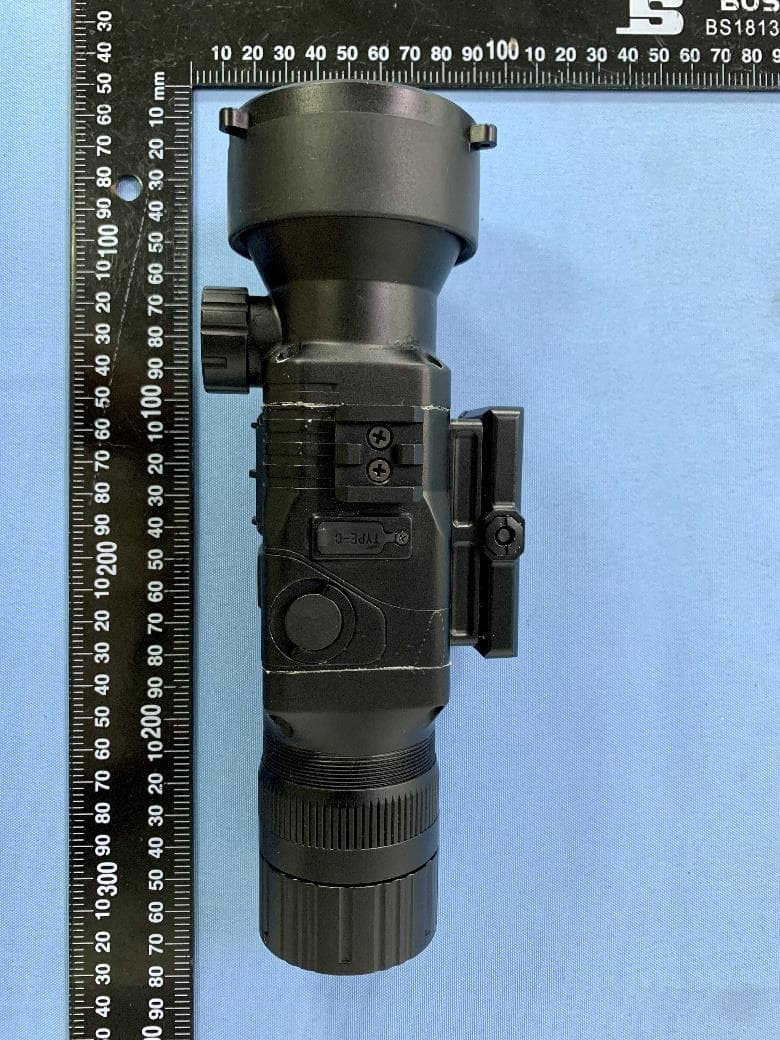
2AWAA-RS6
Sep 01, 2024Thermal Imager
Equipment Class
DTS - Digital Transmission System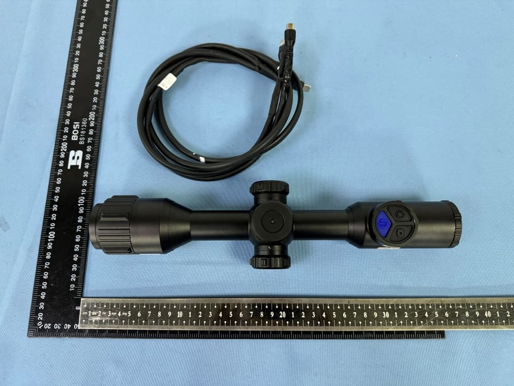
2AWAA-RS7
Aug 01, 2024Thermal Imager
Equipment Class
DTS - Digital Transmission System
2AWAA-MS735MH
Jan 09, 2024Thermal Imager
Equipment Class
DTS - Digital Transmission System
2AWAA-T12M
Jan 04, 2024Thermal Imaging Camera
Equipment Class
DTS - Digital Transmission System