2AXUI-103S4G TABLET PC
CHITECH SHENZHEN TECHNOLOGY CO.,LTD
Click to zoom
Application Details
- Equipment Class
- NII - Unlicensed National Information Infrastructure TX
- Date of Grant
- Nov 27, 2022
- Application Purpose
- Original Equipment
- Date of Application
- Nov 27, 2022
- Equipment Note
- 4G TABLET PC
- Frequency Range
- 5745.00000000 - 5825.00000000
- Country
- China
Documents & Files
Document Text
Text extracted from the exhibit documents filed with the FCC. Open a document above to read the original.
Users Manual
4G TABLET PC Model:103S 10.1 This device complies with part 15 of the FCC rules. Operation is subject to the following two conditions: ( 1) This device may not cause harmful interference, and (2) this device must accept any interference received, including interference that may cause undesired operation. 15.21 Informatio n to the user. Any changes or modifications not expressly approved by the party responsible for compliance could void the user's authority to operate the equipment. 15.105 Information for the user. Note: This equipment has been tested and found to comply with the limits for a Class B digital device, pursuant to part 15 of the FCC rules. These limits are designed to provide reasonable protection against harmful interference in a residential installation. This equipment generates, uses and can radiate radio frequency energy and, if not installed and used in accordance with theinstructions, may cause interference to radio communications. However, there is no guarantee that interference will not occur in a particular installation. If this equipment does cause harmful interference to radio or television reception, which can be determined by turning the equipment off and on, the user is encouraged to try to correct the interference by one or more of the following measures: -Reorient or relocate the receiving antenna. -Increase the separation between the equipment and receiver. -Connecting the equipment to a socket on a circuit different from that to which the receiver is connected. -Contact with the provider or a radio f TV technician for help. Specific absorption rate (SAR): This Tablet PC meets the government's requirements for exposure to radio waves. The guidelines are based on standards developed by independent scientific organizations through periodic and thorough evaluation of scientific studies. The standards include a margin of safety designed to ensure the safety of all people regardless of their age or health. The FCC Statement of Exposure to RF and the SAR limit for the United States (FCC) is 1.6 W/kg average for each gram of tissue. This device was tested for typical operations of use on the body, with the back of the Tablet PC at 0mm from the body. To maintain compliance with FCC RF exposure requirements, use accessories that maintain a distance of 0mm between the user's body and the back of the Tablet PC. The use of belt clips, covers and similar accessories must not contain metallic components in their assembly. The use of accessories that do not meet these requirements may not meet FCC RF exposure requirements and should be avoided. Functioning in the bo dy This device was tested for typical operations of use in the body. To comply with RF exposure requirements, a minimum separation distance of 0mm must be maintained between the user's b ody and the telephone, including the antenna. Third-party accessories such as belt clips. covers and similar accessories used with this device should not contain metallic components, accessories that do not meet these RF exposure requirements and should be avoided from use on the body. Use only the supplied antenna or an approved antenna.
Cover Letter(s)
CHITECH SHENZHEN TECHNOLOGY CO.,LTD Agent Authorization Letter (2022-11-22) Eurofins Electrical and Electronic Testing NA, Inc. 914 West Patapsco Avenue Baltimore, MD 21230 RE: LETTER OF AGENT AUTHORIZATION To Whom It May Concern: We, the undersigned, hereby authorize Shenzhen NTEK Testing Technology Co., Ltd. 1/F, Building E, Fenda Science Park Sanwei, Xixiang, Bao'an District, Shenzhen, Guangdong, China Alex.li [email protected] to act on our behalf in all matters relating to application for equipment authorization, including the signing of all documents relating to these matters. We also hereby certify that no party to the application authorized hereunder is subject to the denial of benefits, including FCC benefits, pursuant to Section 5301 of the Anti-Drug Abuse Act of 1988, 21 U.S.C.853(a). This agreement expires one year from the current date. Sincerely, Lydia Deng / Manager Date/City: 2022-11-22 / Shenzhen Phone: 86-0755-21380496 Fax: 86-0755-21380496 E-mail: [email protected]
Cover Letter(s)
FCC Software Configuration Control Declaration CHITECH SHENZHEN TECHNOLOGY CO.,LTD FCC Software Configuration Control Declaration Date: November 22, 2022 Federal Communications Commission 7435 Oakland Mills Road Columbia, MD 21046 USA Attn: OET Dept. Product/ Model Number:4G TABLET PC / 103S FCC ID: 2AXUI-103S Regarding FCC Country Code Selection guidelines identified in KDB 594280. “All applications for equipment authorization for transmitters that can have radio parameters, or other technical parameters, reported to the Commission set by software must have an attestation indicating that no third party will have software, or configuration control, to program the device out of compliance of the technical rules under which it has been certified.” We declare that no third party will have software, or configuration control, to program the device out of compliance of the technical rules under which it has been certified. Lydia Deng / Manager Date/City: 22/11/2022 / Shenzhen Phone: 86-0755-21380496 Fax: 86-0755-21380496 E-mail: [email protected]
Cover Letter(s)
CHITECH SHENZHEN TECHNOLOGY CO.,LTD 594280D02U-NIIDeviceSecurityv01r03 Page1 Date: 11/22/2022 SOFTWARESECURITYREQUIREMENTS FORU-NII DEVICES (594280 D02 U-NII Device Security 1.3, 11/12/15) Company Name: CHITECH SHENZHEN TECHNOLOGY CO.,LTD FCC ID: 2AXUI-103S Product Name: 4G TABLET PC SOFTWARE SECURITY DESCRIPTION General Description Q. 1. Describe how any software/firmware updates for elements than can affect the device’s RF parameters will be obtained, downloaded, validated and installed. For software that is accessed through manufacturer’s website or device’s management system, describe the different levels of security as appropriate. A. It can update from wireless access based on WiFi, A system update service runs in the device, users could only upgrade the software from WiFi via the service. And, any new software/firmware can be obtained from the qualified database from a private OTA server of company. The OTA server is based on cloud service, mainly store the software/firmware, the system update service with communicate with the OTA server and negotiate the update process. The update does not affect RF parameter. Q. 2. Describe the RF parameters that are modified by any software/firmware without any hardware changes. Are these parameters in some way limited such that any other software/firmware changes will not allow the device to exceed the authorized RF characteristics? A. All the radio frequency parameters are not modified by any software/firmware without any hardware changes, because the software/firmware can’t changes the radio frequency parameters Q. 3. Describe in detail the authentication protocols that are in place to ensure that the source of the RF-related software/firmware is valid. Describe in detail how the RF-related software is protected against modification. A. Software/firmware are digitally signed and encrypted using proprietary handshaking, authorization and provisioning protocols. Secure Sockets Layer is used protocol for encrypting information over the internet. Therefore, Can ensure that the source of the software/firmware is legitimate Q. 4. Describe in detail any encryption methods used to support the use of legitimate RF-related software/firmware. A. RSA algorithm is used to sign and encrypt the software/firmware using a private key Q. 5. For a device that can be configured as a master and client (with active or passive scanning), explain how the deviceensurescomplianceforeachmode?Inparticular,ifthedeviceactsas master in some band of operation and client in another; how is compliance ensured in each band of operation? A. The equipment only can be configured as a client device, And user can’t access to change client feature per band. CHITECH SHENZHEN TECHNOLOGY CO.,LTD 594280D02U-NIIDeviceSecurityv01r03 Page2 Third-PartyAccessControl 1. Explain if any third parties have the capability tope rate a U.S.-sold device on any other regulatory domain, frequencies, or in any manner that may allow the device to operate in violation of the device’s authorization if activated in the U.S. The modules firmware is stored in the ROM, third parties could not access the system image because they have no private key to do this. Under this pre-condition, A third party cannot change radio parameters. different country have different mechanism(likeness country code).It can control the module’s parameter, such as Channel, Power, Bandwidth and etc. when sale to US, decided to device only have US mechanism(not certified frequencies are blocked). Out of US mechanism, the parameter(Channel, Power, Bandwidth and etc) is un allow able. So it cannot have capability to operate the device. 2. Describe, if the device permits third-party software or firmware installation, what mechanisms are provided by the manufacturer to permit integration of such functions while ensuring that the RF parameter soft he device cannot be operated outside its authorization for operation in the U.S. In the description include what control sand/or agreements are in place with providers of third-party functionality to ensure the devices’ underlying RF parameters are unchanged and how the manufacturer verifies the functionality. The underlying code of user program owned the company will prevents third party from loading non-US versions of the software/firmware on the device, the device will protected from “flashing” and the installation of third-party firmware Through judging the false identification code. No one can generate a legal image without private key, if a illegal image is flashed in the device, the device won’t start up. 3. For Certified Transmitter modular devices, describe how the module grantee ensures that host manufacturers fully comply with these software security requirements for U-NII devices. If the module is controlled through driver software loaded in the host, describe how the drivers are controlled and managed such that the modular transmitter RF parameters are not modified out side the grant of authorization. N/A SOFTWARE CONFIGURATIONDESCRIPTION USER-CONFIGURATIONGUIDE Q. 1. Describe the user configurations permitted through the UI. If different levels of access are permitted for professional installers, system integrator sorend-users, descry be the differences. A. The UI is accessible to the end user, but the UI never gives access for specific operation parameters which are Channel, Power, Bandwidth, or Country code settings a. What parameters are viewable and configurable by different parties? 9 All RF parameter is not viewable by User b. What parameters are accessible or modifiable by the professional installer or system CHITECH SHENZHEN TECHNOLOGY CO.,LTD 594280D02U-NIIDeviceSecurityv01r03 Page3 integrators? N/A (1)Are the parameters in some way limited, sothattheinstallerswillnotenterparametersthatexceedthoseauthorized? N/A (2)What controls exist that the user cannot operate the device outside its authorization in the U.S.? N/A c. What parameters are accessible or modifiable by the e…
Text truncated - open the document above for the full version.
Cover Letter(s)
CHITECH SHENZHEN TECHNOLOGY CO.,LTD Long Term Confidentiality Request Letter (26/11/2022) Eurofins Electrical and Electronic Testing NA, Inc. 914 West Patapsco Avenue Baltimore, MD 21230 RE: CONFIDENTIALITY REQUEST FOR Product: 4G TABLET PC Model No.:103S FCC ID:2AXUI-103S To Whom It May Concern: This letter serves as an official request for confidentiality under sections 0.457 and 0.459 of CFR 47. We have requested that the Schematic Diagram Block Diagram Operational Description Software Security Requirements for UNII devices BOM/Part/PCB Layout Tune up procedure Required to be submitted with this application be permanently withheld from public review. Above mentioned document contains detailed system and equipment description are considered as proprietary information in operation of the equipment. The public disclosure of above documents might be harmful to our company and would give competitor an unfair advantage in the market. It is our understanding that all measurement test reports, FCC ID label format and correspondent during certification review process cannot be granted as confidential documents and those information will be available for public review once the grant of equipment authorization is issued. Please contact me if there is any information you may need. Sincerely, Lydia Deng / Manager Date/City: 26/11/2022 / Shenzhen Phone: 86-0755-21380496 Fax: 86-0755-21380496 E-mail: [email protected]
External Photos
ATTACHMENT PHOTOGRAPHS OF EUT Photo 1 Photo 2 Photo 3 Photo 4 Photo 5 Photo 6 Photo 7 Photo 8 Photo 9 Photo 10
ID Label/Location Info
50mm 30mm 101,NO.48,Xiashijia Road,Gongming Town,Guangming Dist.,Shenzhen,China ManufacturerCHITECH SHENZHEN TECHNOLOGY CO.,LTD Made in China INPUT: 5V 2.0AModel:103S FCC ID:2AXUI-103S
Internal Photos
ATTACHMENT PHOTOGRAPHS OF EUT Photo 1 Photo 2 Photo 3 Photo 4 Photo 5 Photo 6 Photo 7 Photo 8 Photo 9 Photo 10 Photo 11 Photo 12 BT/WIFI2.4G/5G ANT Photo 13 GSM/WCDMA/LTE ANT
RF Exposure Info
Page 1 of 155 Report No.: STR220923002007E FCC SAR EVALUATION REPORT In accordance with the requirements of FCC 47 CFR Part 2(2.1093), ANSI/IEEE C95.1-1992 and IEEE Std 1528-2013 Product Name: 4G TABLET PC Trademark: hatch Model Name: 103S Family Model: N/A FCC ID: 2AXUI-103S Report No.: STR220923002007E Prepared for CHITECH SHENZHEN TECHNOLOGY CO.,LTD 101, NO.48, Xiashijia Road, Gongming Town, Guangming Dist., Shenzhen, China Prepared by Shenzhen NTEK Testing Technology Co., Ltd. 1/F, Building E, Fenda Science Park, Sanwei Community, Xixiang Street, Bao'an District, Shenzhen 518126 P.R.China. Tel. 400-800-6106, 0755-2320 0050, 0755-2320 0090 Website: http://www.ntek.org.cn Page 2 of 155 Report No.: STR220923002007E TEST RESULT CERTIFICATION Applicant’s name .................. : CHITECH SHENZHEN TECHNOLOGY CO.,LTD Address .................................. : 101, NO.48, Xiashijia Road, Gongming Town, Guangming Dist., Shenzhen, China Manufacturer's Name ........... : CHITECH SHENZHEN TECHNOLOGY CO.,LTD Address .................................. : 101, NO.48, Xiashijia Road, Gongming Town, Guangming Dist., Shenzhen, China Product description Product name ......................... : 4G TABLET PC Trademark ............................ : hatch Model Name ......................... : 103S Family Model .......................... : N/A Standards .............................. : FCC 47 CFR Part 2(2.1093) ANSI/IEEE C95.1-1992 IEEE Std 1528-2013 Published RF exposure KDB procedures This device described above has been tested by Shenzhen NTEK. In accordance with the measurement methods and procedures specified in IEEE Std 1528-2013 and KDB 865664 D01. Testing has shown that this device is capable of compliance with localized specific absorption rate (SAR) specified in FCC 47 CFR Part 2(2.1093) and ANSI/IEEE C95.1-1992. The test results in this report apply only to the tested sample of the stated device/equipment. Other similar device/equipment will not necessarily produce the same results due to production tolerance and measurement uncertainties. This report shall not be reproduced except in full, without the written approval of Shenzhen NTEK, this document may be altered or revised by Shenzhen NTEK, personal only, and shall be noted in the revision of the document. Test Sample Number .............................. T220923002R002 Date of Test Date (s) of performance of tests ............. : Sep. 23, 2022 ~ Oct. 14, 2022 Date of Issue .......................................... : Nov. 08, 2022 Test Result .............................................. : Pass Prepared By (Test Engineer) : (Jacob Chen) Approved By (Lab Manager) : (Alex Li) Page 3 of 155 Report No.: STR220923002007E ※ ※ Revision History ※ ※ REV. DESCRIPTION ISSUED DATE REMARK Rev.1.0 Initial Test Report Release Nov. 08, 2022 Jacob Chen Page 4 of 155 Report No.: STR220923002007E TABLE OF CONTENTS 1. General Information ............................................................................................ 6 1.1. RF exposure limits .................................................................................... 6 1.2. Statement of Compliance ........................................................................ 7 1.3. EUT Description ....................................................................................... 7 1.4. Test specification(s) .................................................................................. 8 1.5. Ambient Condition ................................................................................... 8 2. SAR Measurement System ................................................................................... 9 2.1. SATIMO SAR Measurement Set-up Diagram ............................................ 9 2.2. Robot ..................................................................................................... 10 2.3. E-Field Probe .......................................................................................... 11 2.3.1. E-Field Probe Calibration ................................................................. 11 2.4. SAM phantoms ...................................................................................... 12 2.4.1. Technical Data .................................................................................. 13 2.5. Device Holder ........................................................................................ 14 2.6. Test Equipment List ................................................................................ 15 3. SAR Measurement Procedures .......................................................................... 17 3.1. Power Reference ................................................................................... 17 3.2. Area scan & Zoom scan .......................................................................... 17 3.3. Description of interpolation/extrapolation scheme .............................. 19 3.4. Volumetric Scan ..................................................................................... 19 3.5. Power Drift ............................................................................................ 19 4. System Verification Procedure .......................................................................... 20 4.1. Tissue Verification ................................................................................. 20 4.1.1. Tissue Dielectric Parameter Check Results ...................................... 21 4.2. System Verification Procedure .............................................................. 22 4.2.1. System Verification Results .............................................................. 23 5. SAR Measurement variability and uncertainty .................................................. 24 5.1. SAR measurement variability ................................................................. 24 5.2. SAR measurement uncertainty .............................................................. 24 6. RF Exposure Posit…
Text truncated - open the document above for the full version.
RF Exposure Info
Page 111 of 155 Report No.: STR220923002007E Page 112 of 155 Report No.: STR220923002007E Page 113 of 155 Report No.: STR220923002007E Page 114 of 155 Report No.: STR220923002007E Page 115 of 155 Report No.: STR220923002007E Page 116 of 155 Report No.: STR220923002007E Page 117 of 155 Report No.: STR220923002007E Page 118 of 155 Report No.: STR220923002007E Page 119 of 155 Report No.: STR220923002007E Page 120 of 155 Report No.: STR220923002007E Page 121 of 155 Report No.: STR220923002007E Page 122 of 155 Report No.: STR220923002007E Page 123 of 155 Report No.: STR220923002007E Page 124 of 155 Report No.: STR220923002007E Page 125 of 155 Report No.: STR220923002007E Page 126 of 155 Report No.: STR220923002007E Page 127 of 155 Report No.: STR220923002007E Page 128 of 155 Report No.: STR220923002007E Page 129 of 155 Report No.: STR220923002007E Page 130 of 155 Report No.: STR220923002007E Page 131 of 155 Report No.: STR220923002007E Page 132 of 155 Report No.: STR220923002007E Page 133 of 155 Report No.: STR220923002007E Page 134 of 155 Report No.: STR220923002007E Page 135 of 155 Report No.: STR220923002007E Page 136 of 155 Report No.: STR220923002007E Page 137 of 155 Report No.: STR220923002007E Page 138 of 155 Report No.: STR220923002007E Page 139 of 155 Report No.: STR220923002007E Page 140 of 155 Report No.: STR220923002007E Page 141 of 155 Report No.: STR220923002007E Page 142 of 155 Report No.: STR220923002007E Page 143 of 155 Report No.: STR220923002007E Page 144 of 155 Report No.: STR220923002007E Page 145 of 155 Report No.: STR220923002007E Page 146 of 155 Report No.: STR220923002007E Page 147 of 155 Report No.: STR220923002007E Page 148 of 155 Report No.: STR220923002007E Page 149 of 155 Report No.: STR220923002007E Page 150 of 155 Report No.: STR220923002007E <Justification of the extended calibration> If dipoles are verified in return loss (<-20dB, within 20% of prior calibration for below 3GHz, and <-8dB, within 20% of prior calibration for 5GHz to 6GHz), and in impedance (within 5 ohm of prior calibration), the annual calibration is not necessary and the calibration interval can be extended. <Head 835MHz> Return Loss (dB) Delta (%) Impedance Delta(ohm) Date of Measurement -25.44 - 54.40 - Mar. 01, 2021 -25.803 1.43 54.492 0.092 Feb. 28, 2022 The return loss is <-20dB, within 20% of prior calibration; the impedance is within 5 ohm of prior calibration. Therefore the verification result should support extended calibration. Dipole Verification Data Page 151 of 155 Report No.: STR220923002007E <Head 1800MHz> Return Loss (dB) Delta (%) Impedance Delta(ohm) Date of Measurement -28.85 - 47.90 - Mar. 01, 2021 -28.545 1.06 47.809 0.091 Feb. 28, 2022 The return loss is <-20dB, within 20% of prior calibration; the impedance is within 5 ohm of prior calibration. Therefore the verification result should support extended calibration. Dipole Verification Data Page 152 of 155 Report No.: STR220923002007E <Head 1900MHz> Return Loss (dB) Delta (%) Impedance Delta(ohm) Date of Measurement -24.79 - 50.80 - Mar. 01, 2021 -24.518 1.10 50.516 0.284 Feb. 28, 2022 The return loss is <-20dB, within 20% of prior calibration; the impedance is within 5 ohm of prior calibration. Therefore the verification result should support extended calibration. Dipole Verification Data Page 153 of 155 Report No.: STR220923002007E <Head 2450MHz> Return Loss (dB) Delta (%) Impedance Delta(ohm) Date of Measurement -23.18 - 56.30 - Mar. 01, 2021 -23.39 0.91 56.342 0.042 Feb. 28, 2022 The return loss is <-20dB, within 20% of prior calibration; the impedance is within 5 ohm of prior calibration. Therefore the verification result should support extended calibration. Dipole Verification Data Page 154 of 155 Report No.: STR220923002007E <Head 5200MHz> Return Loss (dB) Delta (%) Impedance Delta(ohm) Date of Measurement -9.15 - 21.17 - Mar. 01, 2021 -9.1819 0.35 21.191 0.021 Feb. 28, 2022 The return loss is <-8dB, within 20% of prior calibration; the impedance is within 5 ohm of prior calibration. Therefore the verification result should support extended calibration. Dipole Verification Data Page 155 of 155 Report No.: STR220923002007E <Head 5800MHz> Return Loss (dB) Delta (%) Impedance Delta(ohm) Date of Measurement -14.30 - 54.74 - Mar. 01, 2021 -14.349 0.34 55.115 0.375 Feb. 28, 2022 The return loss is <-8dB, within 20% of prior calibration; the impedance is within 5 ohm of prior calibration. Therefore the verification result should support extended calibration. Dipole Verification Data _______________________________________END _____________________________________
Test Report
Shenzhen Qianmu Communication Technology Co., Ltd Shenzhen Qianmu Communication Technology Co., Ltd. Contact: Wang Zhiqiang Contact: 13760153961 Tel: 0755-21633653 Fax: 0755-21633541 No.425 and No.443, Floor 4, Block A, Huafeng Zhigu-Hangcheng High-tech Industrial Park, Sanwei Community, Hangcheng Street, Baoan District, Shenzhen 第 1 页 Antenna acknowledgement Applicable model H106T Customer Shenzhen zhiteng Yongsheng technology co., ltd Specification description Product content Specification Customer material code Specification description 4G antenna FPC/Black/Character QM-H106T-MAIN + Fourth generation terminal φ 0.81*95mm + conductive cloth Three-in-one antenna FPC/Black/Character QM-H106T-W/G/B + Fourth generation terminal φ 0.81*132mm + conductive cloth Change resume Serial number Date Version Brief introduction of changes 1 2022-11-24 V1.0 New project 2 3 Supplier sample confirmation R&D Structure Audit Judge PASS FAIL Customer sample confirmation Electron Structure Project Procureme nt Quality Audit Reasons for rejection or other precautions: 第 2 页 1. Electrical performance test report of main antenna 1.1 Test items and equipment Test item Equipment Passive test ① . VSWR parameter ② . Return loss parameter Network Analyzer: HP8753D Antenna Test System (ETS Test System, Network Analyzer, Comprehensive Tester) Active test 1. Transmit power 2. Receive level 3. Receive sensitivity Comprehensive tester: Agilent E5515C3D darkroom antenna test system (ETS test system, comprehensive tester) 1.2 GSM Passive Test Report VSWR parameter value Frequency (MHZ) 794 960 1710 1880 2170 2500 2690 RL 2.7 1.71 1.8 1.8 3.1 1.7 1.3 第 3 页 Return loss parameter value Frequency (MHZ) 794 960 1710 1880 2170 2500 2690 RL -6.5 -5.5 -10.2 -10.4 -5.7 -11 -16.3 2、Description of matching circuit According to your original matching circuit, no changes have been made. 第 4 页 3、Test report GSM900 DCS1800 Channel 1 62 124 512 698 885 Max Power 20.23 20.41 20.67 TRP 17.03 17.14 17.21 Min Sensitivity -100.34 TIS -96.23 GSM850 PCS1900 Channel 128 190 251 512 661 810 Max Power 27.84 27.52 27.41 29.04 29.81 29.38 TRP 23.67 23.41 23.28 25.14 25.56 25.74 Min Sensitivity -100.13 -105.38 TIS -96.17 -101.59 W850 W900 Channel 4357 4408 4458 2937 3013 3088 Max Power 18.23 18.14 18.06 15.14 15.53 16.12 TRP 15.54 15.36 15.18 13.03 13.67 13.83 Min Sensitivity -100.23 -100.14 TIS -97.14 -96.87 W1900 W2100 Channel 9662 9800 9938 10562 10700 10838 Max Power 23.12 23.43 23.67 23.26 22.57 22.16 TRP 19.02 19.26 19.55 19.18 18.67 18.29 Min Sensitivity -108.19 -108.05 TIS -104.03 -103.84 B1 B2 Channel 18050 18300 18550 18650 18900 19150 Max Power 20.23 19.76 19.54 22.36 22.17 21.28 TRP 16.72 15.8 15.36 18.49 18.23 17.19 Min Sensitivity -94.03 -90.14 TIS -90.24 -86.32 B4 B5 Channel 20000 20175 20350 20450 20525 20600 Max Power 22.76 22.34 21.48 17.53 17.36 17.12 TRP 18.82 18.26 17.57 14.56 14.27 14.03 Min Sensitivity -93.92 -88.24 TIS -90.01 -84.56 第 5 页 B7 B12 Channel 20800 21100 21400 23060 23095 23130 Max Power 20.47 20.03 20.36 14.03 14.27 14.46 TRP 16.3 15.6 16.27 11.01 11.36 11.58 Min Sensitivity -95.58 -86.73 TIS -92.06 -83.54 B17 B34 Channel 23780 23790 23800 36250 36275 36300 Max Power 13.14 13.37 13.56 17.28 18.36 18.04 TRP 10.02 10.14 10.38 13.59 14.48 14.17 Min Sensitivity -85.23 -91.05 TIS -82.27 -87.4 B38 B39 Channel 37850 38000 38150 38350 38450 38550 Max Power 17.03 16.68 16.47 21.46 21.09 19.27 TRP 13.23 12.7 12.27 17.68 17.11 15.89 Min Sensitivity -92.08 -89.88 TIS -87.55 -85.61 B40 B41 Channel 38750 39150 39550 40340 40740 41140 Max Power 21.87 21.53 19.26 17.53 17.41 17.33 TRP 17.62 17.28 15.55 13.88 13.69 13.55 Min Sensitivity -91.89 -90.06 TIS -87.44 -86.29 4. Active data of WIFI antenna WiFi 2400 ~ 2500Mz 802.11 b 11MBps Channel 1 6 11 TRP 11.04 9.02 12.17 TIS -80.99 -81.25 -75.06 WIFI5000 ~ 5800Mz 802.11 a 54MBps Channel 36 161 165 TRP 9.34 5.16 6.17 TIS -63.99 -64.73 -65.39 第 6 页 5. WIFI passive benefit and gain diagram 2.4 G-2. 5G 第 7 页 5G-5.8G 第 8 页 4、Environmental treatment and antenna placement Main antenna position Conductive cloth is attached to the copper leakage area of antenna and the screen is grounded GWB Antenna Position Conductive cloth is attached to the copper leakage area of antenna and the screen is grounded The laser engraving area of shell material is attached with conductive foam heel screen and grounding of main board 第 9 页 5、GPS and WIFI measurement v 第 10 页 6、Structural drawing 第 11 页
Test Report
Report No.: STR220923002004E Page 1 of 94 5.2G: Duty Cycle Condition Mode Frequency (MHz) Antenna Duty Cycle (%) Correction Factor (dB) NVNT a 5180 Ant1 98.14 0.08 NVNT a 5200 Ant1 98.18 0.08 NVNT a 5240 Ant1 98.19 0.08 NVNT ac20 5180 Ant1 98.07 0.08 NVNT ac20 5200 Ant1 98.06 0.09 NVNT ac20 5240 Ant1 98.06 0.09 NVNT ac40 5190 Ant1 96.26 0.17 NVNT ac40 5230 Ant1 96.24 0.17 NVNT ac80 5210 Ant1 92.89 0.32 NVNT n20 5180 Ant1 98.06 0.09 NVNT n20 5200 Ant1 98.04 0.09 NVNT n20 5240 Ant1 98.04 0.09 NVNT n40 5190 Ant1 96.16 0.17 NVNT n40 5230 Ant1 96.17 0.17 Duty Cycle NVNT a 5180MHz Ant1 Report No.: STR220923002004E Page 2 of 94 Duty Cycle NVNT a 5200MHz Ant1 Duty Cycle NVNT a 5240MHz Ant1 Report No.: STR220923002004E Page 3 of 94 Duty Cycle NVNT ac20 5180MHz Ant1 Duty Cycle NVNT ac20 5200MHz Ant1 Report No.: STR220923002004E Page 4 of 94 Duty Cycle NVNT ac20 5240MHz Ant1 Duty Cycle NVNT ac40 5190MHz Ant1 Report No.: STR220923002004E Page 5 of 94 Duty Cycle NVNT ac40 5230MHz Ant1 Duty Cycle NVNT ac80 5210MHz Ant1 Report No.: STR220923002004E Page 6 of 94 Duty Cycle NVNT n20 5180MHz Ant1 Duty Cycle NVNT n20 5200MHz Ant1 Report No.: STR220923002004E Page 7 of 94 Duty Cycle NVNT n20 5240MHz Ant1 Duty Cycle NVNT n40 5190MHz Ant1 Report No.: STR220923002004E Page 8 of 94 Duty Cycle NVNT n40 5230MHz Ant1 Report No.: STR220923002004E Page 9 of 94 Maximum Conducted Output Power Condition Mode Frequency (MHz) Antenna Conducted Power (dBm) Duty Factor (dB) Total Power (dBm) Limit (dBm) Verdict NVNT a 5180 Ant1 9.833 0.08 9.913 24 Pass NVNT a 5200 Ant1 9.48 0.08 9.56 24 Pass NVNT a 5240 Ant1 9.948 0.08 10.028 24 Pass NVNT ac20 5180 Ant1 8.588 0.08 8.668 24 Pass NVNT ac20 5200 Ant1 8.913 0.09 9.003 24 Pass NVNT ac20 5240 Ant1 8.722 0.09 8.812 24 Pass NVNT ac40 5190 …
Text truncated - open the document above for the full version.
Contact Information
Applicant
Lydia Deng(Manager)
Technical Contact
Shenzhen NTEK Testing Technology Co., Ltd.Alex Li
[email protected]+86-755-6115-9384
1/F, Building E, Fenda Science Park Sanwei, · Shenzhen, Guangdong · China
Test Firm
Shenzhen NTEK Testing Technology Co., Ltd.Alex Li
[email protected]+86-755-6115-9384
Technical Specifications
| # | Rule Parts | Frequency Range | Power Output |
|---|---|---|---|
| 2 | 15E | 5.75 GHz - 5.83 GHz | 9.79 mW |
Other Applications from CHITECH SHENZHEN TECHNOLOGY CO.,LTD

2AXUI-TID10
Apr 10, 2023SMART PHOTO FRAME
Equipment Class
DTS - Digital Transmission System
2AXUI-M1
Apr 08, 2023Mini PC
Equipment Class
NII - Unlicensed National Information Infrastructure TX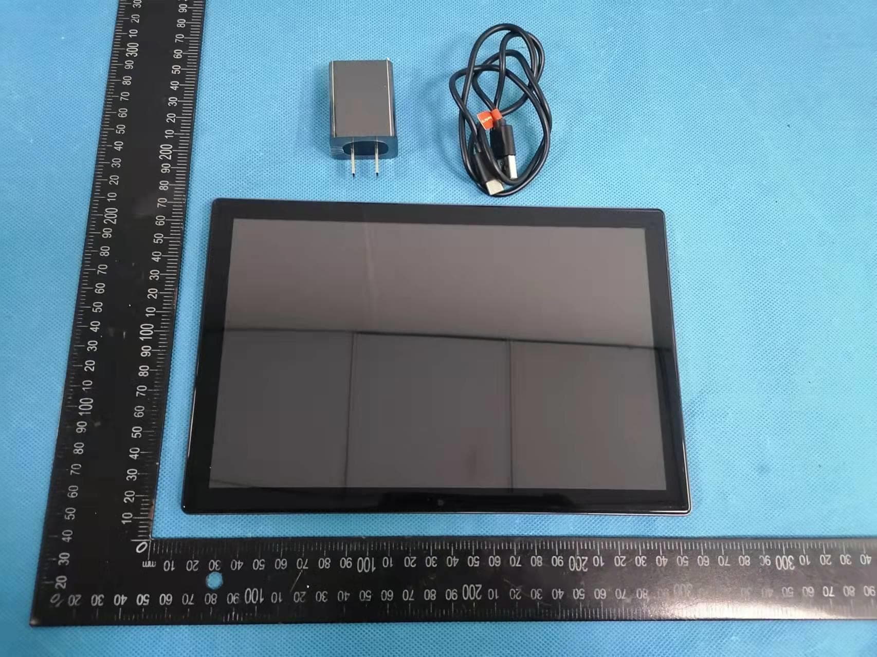
2AXUI-T10
Jan 18, 2022Tablet
Equipment Class
DTS - Digital Transmission System
2AXUI-102S
Nov 23, 20204G TABLET PC
Equipment Class
DSS - Part 15 Spread Spectrum Transmitter