2BABY696763Wifi Photo Frame
GuangXi BeiLiu JinBao Electronic Co., Ltd.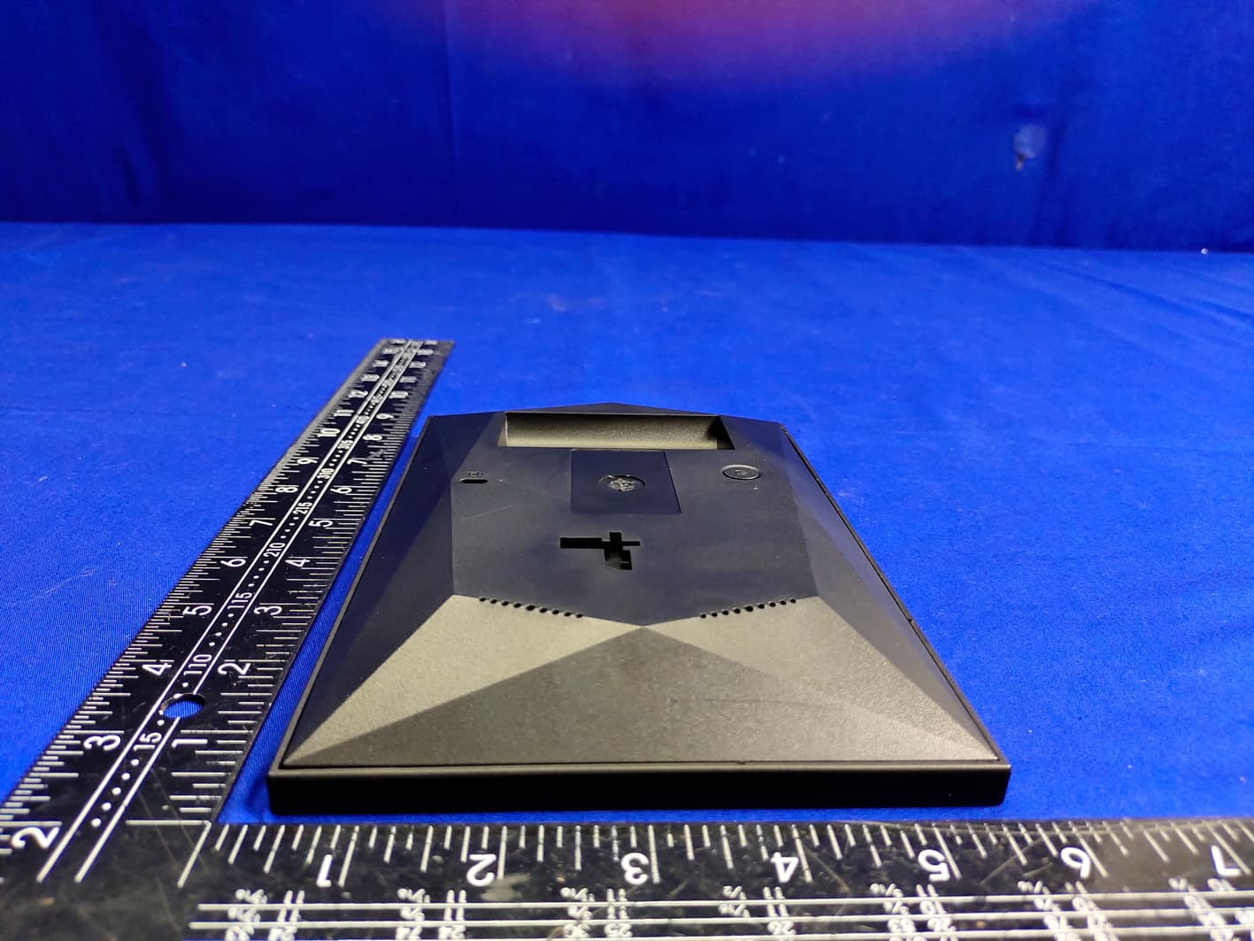
Click to zoom
Application Details
- Equipment Class
- DTS - Digital Transmission System
- Date of Grant
- May 02, 2023
- Application Purpose
- Original Equipment
- Date of Application
- May 02, 2023
- Equipment Note
- Wifi Photo Frame
- Frequency Range
- 2412.00000000 - 2462.00000000
- Country
- China
Documents & Files
Document Text
Text extracted from the exhibit documents filed with the FCC. Open a document above to read the original.
Users Manual
WiFi PHOTO FRAME USER MANUAL Model No.: PFW763B PLEASE READ BEFORE OPERATING THIS EQUIPMENT Key Points This manual includes security measures and correct operating methods. For personal safety, please make sure to read this manual before using. Thank you! 1. The machine adopts capacitive touch screen, you can just touch it by finger or click with capacitive pen for operation. (Never use the sharp objects to click the screen, or the touch screen may be damaged). 2. Do not put the device at any high temperature, high humidity or dusty place. 3. Do not drop or crash the device to prevent the violent impacting between the display and the capacitive touch screen. Or the customers have to take the consequence by them- selves. 4. Don't use the different type charger or it may make the device burned. We assume no liability for the damage. Please contact with our agent if you need the original adaptor. 5. Do not disconnect the device while formatting, or it may make the error. Our company won't bear the duty for the loss of the memory erasing on account of the damage, repair or some other reason. Please operate the device according to the user manual rightly and backup the important data in time. 6. Do not dismantle this device by yourself, and do not polish it with alcohol, dilution, or benzene. 7. Do not use this device where electronics is forbidden, such as on the airplane. 8. Do not use this device while walking and driving, avoiding traffic accident. 9. USS is for transferring data but NOT for charging. Virus can damage this device. So please use proper computer antivirus and keep it updated. For any support needed for this device please contact the company or the authorized distributor. Any unauthorized dismantling of the device will make the warranty null and void. We reserve the right to keep the change of the products, the specification and design is subject to change without notice! Location of Control 1. POWER After connecting power adapter, the unit will power on automatically for the first time. When it is on, press and hold power button for approximately 3 seconds to access reboot or power off menu. Short press on power button will turn off/on screen (but leave the photo frame in on position) 2. RESET Use a needle or paper clip to reset unit. 3. USB Connect with a USB flash driver via OTG cable or connect to a computer to transfer data, can import photos from USB disk/computer to photo frame, can't copy photos from photo frame to USB disk/computer, can't playback photos from USB disk directly. Note: The micro USB port is only for data transferring, not for charging. 4. Micro SD Load external micro SD memory cards here. Note: Consumer can import photos from micro SD card to photo frame, can copy photos from photo frame to micro SD card, but can't playback photos from micro SD card directly. 5. DC Connect DC adapter to power on the device. 6. Lock hole Connect to anti-theft lock (not included) 7. Stand Slot Insert the included stand attachment to set your frame on a table or other surface. Supports both portrait and landscape orientation Packing contents 1 photo frame, 1 adapter, 1 stand, 1 user manual Getting started Thank you for purchasing your very own frameo. If you are new to using frameo then start by following the frameo quick setup on page 3 or follow the on screen guide when powering it on for the first time. Once you have set up your frameo, start connecting it to your friends and family. Frameo app To send photos to your frame, use the frameo app for iOS or Android Find the frameo app on: Google play by searching for "frameo" App Store by searching for frameo Frameo quick setup When starting your frame for the first time, you will need to setup the frame. ALL SETTINGS CAN BE CHANGED THROUGH THE SETTINGS MENU AFTERWARDS. • First you start by selecting a language. This will be the language used throughout frameo. • Connect your frame to the internet by connecting it to a Wi-Fi. • Frameo may ask you to update to the latest version. It is recommended to update your frame before continuing if asked to. • Enter your name, and the location where you have placed your frame e.g. "Living room", "Kitchen" or "Office". Start using Frameo Next step is to connect Frameo with your friends and family by providing them with a code from your frame. If you want to be able to send photos to the frame yourself, start by downloading the app for iOS or Android on App Store or Google Play. Then use the code to connect your frame and app as described below. Connecting a new friend: • Make sure that your friend has downloaded and installed the Frameo app • Click the add friend icon on your frame . A dialog will appear showing a unique code which is valid for 24 hours. • Now share this code in whatever fashion you prefer e.g. SMS, E-Mail, IM, phone call, to your friend. ONCE YOUR FRIENDS HAVE ADDED THE CODE IN THEIR FRAMEO APP 1 THEY WILL AUTOMATICALLY APPEAR ON YOUR FRAME AND BE ABLE TO SEND YOU PHOTOS. Read chapter Change options for a friend to allow connected friends, to retrieve and share the connection code via the smartphone app. Navigating your Frameo You interact with your frame through its touchscreen. Swipe left or right to go through your photos. To access the menu, simply tap once on the screen, this will show the menu. In the menu you will find the most used features. Add friend This will generate a code that you can share with your friends and family so they can connect and send photos to your frame. Settings Opens the Settings. Power menu Opens the Power menu React Opens the React menu. Note: The React menu can also be accessed by double-tapping on the screen. Hide photo Hides the current photo. This means that the photo will no longer be shown in the slideshow. If needed the photo can be shown again through the settings menu . Gallery Opens a gallery which allows for easy and fast navigation through your photos. Fit to frame/Fill frame This toggles how the photo is shown. The Fill …
Text truncated - open the document above for the full version.
Cover Letter(s)
GuangXi BeiLiu JinBao Electronic Co., Ltd. Date: 2023-4- 6 To: Federal Communications Commission 7435 Oakland Mills Road Columbia, MD FCC ID: 2BABY696763 To Whom It May Concern: This letter is to ascertain thatGuangXi BeiLiu JinBao Electronic Co., Ltd./XinShan Industrial Zone, XiLiang Town, Beiliu City, Guangxi, China. EUT: Wifi Photo Frame MODEL No.: PFW763B, PFW1063B, iPFW763B, iPFW1063B, MET763, MET1063, MD763, MD1063 Has been the units used for conducting FCC compliance testing, the SDoC part Have be tested by EMTEK (SHENZHEN) CO., LTD. If you have any question or concerns, pls. contact us. Sincerely, Client’s signature : Client’s name / title :Jim Wong Contact information / address: GuangXi BeiLiu JinBao Electronic Co., Ltd. /XinShan Industrial Zone, XiLiang Town, Beiliu City, Guangxi, China.
External Photos
EUT EXTERNAL PHOTOGRAPHS ----------------The end----------------
Internal Photos
EUT INTERNAL PHOTOGRAPHS FPC antenna ----------------The end----------------
RF Exposure Info
FCC ID:2BABY696763 RF EXPOSURE EVALUATION According to FCC 1.1310: The criteria listed in the following table shall be used to evaluate the environment impact of human exposure to radio frequency (RF) Radiation as specified in §1.1307(b) Limits for Maximum Permissible Exposure (MPE) Frequency Range(MHz) Electric Field Strength(V/m) Magnetic Field Strength(A/m) Power Density(mW/cm 2 ) Average Time (A) Limits for Occupational/Control Exposures 300-1500 -- -- F/300 6 1500- 100000 -- -- 5 6 (B) Limits for General Population/Uncontrol Exposures 300-1500 -- -- F/1500 6 1500- 100000 -- -- 1 30 11.1 Friis transmission formula: Pd= (Pout*G)\ (4*pi*R 2 ) Where Pd= Power density in mW/cm 2 Pout=output power to antenna in mW G= Numeric gain of the antenna relative to isotropic antenna Pi=3.1416 R= distance between observation point and center of the radiator in cm Pd the limit of MPE, 1mW/cm 2 ,If we know the maximum gain of the nd total power input to the antenna, through the calculation, we will know the distance where the MPE limit is reached. RF Exposure Information: The radiated output power of this device meets the limits of FCC/IC radio frequency exposure limits.This device should be operated with a minimum separation distance of 20cm (8 inches) between the equipment and a person's body. 11.2 Measurement Result Wifi 2.4G TestMode 11G Transmit Power Max: 13.70 dBm Antenna gain: 2.77 dBi Measured power (dBm) Tune-up power (dBm) Max tune-up power (dBm) Antenna Gain Numeric Evaluation result (mW/cm2 ) Power density Limits (mW/cm2 ) 13.70 12 to 14 14 1.89 0.00946 1 *** End of Report ***
Test Report
Shenzhen Xuhang Communication Technology Co., Ltd CUSTOMER GuangXi BeiLiu JinBao Electronic Co., Ltd. PART NAME WIFI Antenna SUPPLIER NO. XH230004(L=40mm) CUSTOMER APPROVED BY APPROVAL CHIEF SUPERVISOR DESIGN CHECK APPROVAL Luo Robert SHANG Date: January 3, 2023. DIRECTORY NO. Contents Number of Page Page Code 1 Spec Cover 1 1 2 DIRECTORY 1 2 3 Te s t Re p o r t s 1 3 4 Matching Circuits 1 4 5 DRAWING 1 5 6 Te s t D a t a 1 6 7 Antenna assembly position 1 7 TEST REPORTS Frequency WIFI(2400~2500MHz) Impedance 50 0hm Nominal V.S.W.R ≤2.0 Return Loss -10dB Max Radiation Omni-directional Gain(Peak) 2.27dBi Polarization Linear,Vertical Admitted Power 1W 连接器 Connector / Physical Properties Antenna Material FPC Cable Type O.D.0.81mm Operating Temp. -10-+60°C Storage Temp. -10-+70°C Cable Color Black Matching Circuits Matching components Element Value Vender E1(0402) E2(0402) 0Ω E3(0402) E4(0402) 0Ω The original matching circuit has been modified. Remove the ground capacitance from the original matching. DRAWING Test Data Antenna assembly position
Test Report
Report No. ENS2303080125W00201R Page 1 of 75 Ver.1.0 $印章$ TE ST REPORT Product Name : Wifi Photo Frame Model Number : PFW763B, PFW1063B, iPFW763B, iPFW1063B, MET763, MET1063, MD763, MD1063 FCC ID : 2BABY696763 Prepared for : GuangXi BeiLiu JinBao Electronic Co., Ltd. Address : XinShan Industrial Zone, XiLiang Town, Beiliu City, Guangxi, China. Prepared by : EMTEK (SHENZHEN) CO., LTD. Address : Building 69, Majialong Industry Zone,Nanshan District, Shenzhen, Guangdong, China Tel: (0755) 26954280 Fax: (0755) 26954282 Report Number : ENS2303080125W00201R Date(s) of Tests : March 9, 2023 to March 16, 2023 Date of issue : March 17, 2023 $二维码$ Report No. ENS2303080125W00201R Page 2 of 75 Ver.1.0 TABLE OF CONTENTS 1 TEST RESULT CERTIFICATION ........................................................................................................ 3 2 EUT TECHNICAL DESCRIPTION ...................................................................................................... 5 3 SUMMARY OF TEST RESULT ........................................................................................................... 6 4 TEST METHODOLOGY ...................................................................................................................... 7 4.1 GENERAL DESCRIPTION OF APPLIED STANDARDS .............................................................. 7 4.2 MEASUREMENT EQUIPMENT USED ........................................................................................ 7 4.3 DESCRIPTION OF TEST MODES ............................................................................................... 8 5 FACILITIES AND ACCREDITATIONS ................................................................................................ 9 5.1 FACILITIES .................................................................................................................................. 9 5.2 EQUIPMENT ................................................................................................................................ 9 5.3 LABORATORY ACCREDITATIONS AND LISTINGS ................................................................... 9 6 TEST SYSTEM UNCERTAINTY ....................................................................................................... 10 7 SETUP OF EQUIPMENT UNDER TEST ........................................................................................... 11 7.1 RADIO FREQUENCY TEST SETUP 1 ........................................................................................ 11 7.2 RADIO FREQUENCY TEST SETUP 2 ........................................................................................ 11 7.3 CONDUCTED EMISSION TEST SETUP ................................................................................... 14 7.4 BLOCK DIAGRAM CONFIGURATION OF TEST SYSTEM ....................................................... 15 7.5 SUPPORT EQUIPMENT ............................................................................................................ 15 8 TEST REQUIREMENTS .................................................................................................................... 16 8.1 DTS 6DB BANDWIDTH .............................................................................................................. 16 8.2 DTS 99% BANDWIDTH ............................................................................................................. 17 8.3 MAXIMUM PEAK CONDUCTED OUTPUT POWER ................................................................. 28 8.4 MAXIMUM POWER SPECTRAL DENSITY ............................................................................... 35 8.5 UNWANTED EMISSIONS IN NON-RESTRICTED FREQUENCY BANDS ............................... 36 8.6 RADIATED SPURIOUS EMISSION ........................................................................................... 46 8.7 CONDUCTED EMISSION TEST ................................................................................................ 72 8.8 ANTENNA APPLICATION .......................................................................................................... 75 Report No. ENS2303080125W00201R Page 3 of 75 Ver.1.0 1 TEST RESULT CERTIFICATION Applicant : GuangXi BeiLiu JinBao Electronic Co., Ltd. Address : XinShan Industrial Zone, XiLiang Town, Beiliu City, Guangxi, China. Manufacturer : GuangXi BeiLiu JinBao Electronic Co., Ltd. Address : XinShan Industrial Zone, XiLiang Town, Beiliu City, Guangxi, China. EUT : Wifi Photo Frame Model Name : PFW763B, PFW1063B, iPFW763B, iPFW1063B,MET763, MET1063, MD763, MD1063 Trademark : GPX, iLive, MET, Modern Measurement Procedure Used: APPLICABLE STANDARDS STANDARD TEST RESULT FCC 47 CFR Part 2, Subpart J FCC 47 CFR Part 15, Subpart C PASS IC RSS-GEN, Issue 5(04-2018)+A1(03-2019)+A2(02-2021) IC RSS-247 Issue 2(02-2017) PASS The above equipment was tested by EMTEK(SHENZHEN) CO., LTD. The test data, data evaluation, test procedures, and equipment configurations shown in this report were made in accordance with the procedures given in ANSI C63.10 (2013) and the energy emitted by the sample EUT tested as described in this report is in compliance with the requirements of FCC Rules Part 2, Part 15.247, IC RSS-247 Issue 2 and IC RSS-GEN, Issue 5. The test results of this report relate only to the tested sample identified in this report. Date of Test : December 9, 2022 to March 16, 2023 Prepared by : Una Yu /Editor Reviewer : Joe Xia /Supervisor Approve & Authorized Signer : Lisa Wang/Manager Report No. ENS2303080125W00201R Page 4 of 75 Ver.1.0 Modified History Version Report No. Revision Date Summary V1.0 ENS2303080125W00201R / Original Report Report No. ENS2303080125W00201R Page 5 of 75 Ver.1.0 2 EUT TECHNICAL DESCRIPTION Note: for more details, please refer to the User’s manual of the EUT. Characteristics Description Product: Wifi Photo Frame Model Number: PFW763B, PFW1063B, iPFW763B, iPFW1063B,MET763, MET1063, MD763, MD1063 (Note: only color and br…
Text truncated - open the document above for the full version.
Test Report
Report No. ENS2303080125W00201R Page 43 of 75 Ver.1.0 Band edge measurements 11B_Ant1_Low_2412 11B_Ant1_High_2462 11G_Ant1_Low_2412 Report No. ENS2303080125W00201R Page 44 of 75 Ver.1.0 11G_Ant1_High_2462 11N20SISO_Ant1_Low_2412 Report No. ENS2303080125W00201R Page 45 of 75 Ver.1.0 11N20SISO_Ant1_High_2462 Report No. ENS2303080125W00201R Page 46 of 75 Ver.1.0 Conducted Spurious Emission 11B_Ant1_2412_0~Reference 11B_Ant1_2412_30~1000 11B_Ant1_2412_1000~26500 Report No. ENS2303080125W00201R Page 47 of 75 Ver.1.0 11B_Ant1_2437_0~Reference 11B_Ant1_2437_30~1000 Report No. ENS2303080125W00201R Page 48 of 75 Ver.1.0 11B_Ant1_2437_1000~26500 11B_Ant1_2462_0~Reference Report No. ENS2303080125W00201R Page 49 of 75 Ver.1.0 11B_Ant1_2462_30~1000 11B_Ant1_2462_1000~26500 Report No. ENS2303080125W00201R Page 50 of 75 Ver.1.0 11G_Ant1_2412_0~Reference 11G_Ant1_2412_30~1000 Report No. ENS2303080125W00201R Page 51 of 75 Ver.1.0 11G_Ant1_2412_1000~26500 11G_Ant1_2437_0~Reference Report No. ENS2303080125W00201R Page 52 of 75 Ver.1.0 11G_Ant1_2437_30~1000 11G_Ant1_2437_1000~26500 Report No. ENS2303080125W00201R Page 53 of 75 Ver.1.0 11G_Ant1_2462_0~Reference 11G_Ant1_2462_30~1000 Report No. ENS2303080125W00201R Page 54 of 75 Ver.1.0 11G_Ant1_2462_1000~26500 11N20SISO_Ant1_2412_0~Reference Report No. ENS2303080125W00201R Page 55 of 75 Ver.1.0 11N20SISO_Ant1_2412_30~1000 11N20SISO_Ant1_2412_1000~26500 Report No. ENS2303080125W00201R Page 56 of 75 Ver.1.0 11N20SISO_Ant1_2437_0~Reference 11N20SISO_Ant1_2437_30~1000 Report No. ENS2303080125W00201R Page 57 of 75 Ver.1.0 11N20SISO_Ant1_2437_1000~26500 11N20SISO_Ant1_2462_0~Reference Report No. ENS2303080125W00201R Page 58 of 75 Ver.1.0 11N20SISO_Ant1_2462_30~1000 11N20SISO_Ant1_2462_1000~26500 Report No. ENS2303080125W00201R Page 59 of 75 Ver.1.0 Report No. ENS2303080125W00201R Page 60 of 75 Ver.1.0 8.6 RADIATED SPURIOUS EMISSION 8.6.1 Applicable Standard According to FCC Part 15.247(d),15.205, 15.209 and KDB 558074 D01 15.247 Meas Guidancev05r02 According to IC RSS-Gen and RSS-247 8.6.2 Conformance Limit According to FCC Part 15.247(d): radiated emissions which fall in the restricted bands, as defined in §15.205(a), must also comply with the radiated emission limits specified in §15.209(a) (see §15.205(c)). According to FCC Part15.205, Restricted bands MHz MHz MHz GHz 0.090-0.110 16.42-16.423 399.9-410 4.5-5.15 10.495-0.505 16.69475-16.69525 608-614 5.35-5.46 2.1735-2.1905 16.80425-16.80475 960-1240 7.25-7.75 4.125-4.128 25.5-25.67 1300-1427 8.025-8.5 4.17725-4.17775 37.5-38.25 1435-1626.5 9.0-9.2 4.20725-4.20775 73-74.6 1645.5-1646.5 9.3-9.5 6.215-6.218 74.8-75.2 1660-1710 10.6-12.7 6.26775-6.26825 123-138 2200-2300 14.47-14.5 8.291-8.294 149.9-150.05 2310-2390 15.35-16.2 8.362-8.366 156.52475-156.52525 2483.5-2500 17.7-21.4 8.37625-8.38675 156.7-156.9 2690-2900 22.01-23.12 8.41425-8.41475 162.0125-167.17 3260-3267 23.6-24.0 12.29-12.293 167.72-173.2 3332-3339 31.2-31.8 12.51975-12.52025 240-285 3345.8-3358 36.43-36.5 12.57675-12.57725 322-335.4 3600-4400 (2) 13.36-13.41 According toFCC Part15.205the level of any transmitter spurious emission in Restricted bands shall not exceed the level of the emission specified in the following table Restricted Frequency(MHz) Field Strength (μV/m) Field Strength (dBμV/m) Measurement Distance 0.009-0.490 2400/F(KHz) 20 log (uV/m) 300 0.490-1.705 24000/F(KHz) 20 log (uV/m) 30 1.705-30 30 29.5 30 30-88 100 40 3 88-216 150 43.5 3 216-960 200 46 3 Above 960 500 54 3 8.6.3 Test Configuration Test according to clause 6.2 radio frequency test setup 8.6.4 Test Procedure This test is required for any spurious emission that falls in a Restricted Band, as defined in Section 15.205. It must be performed with the highest gain of each type of antenna proposed for use with the EUT. Use the following spectrum analyzer settings: For Above 1GHz: The EUT was placed on a turn table which is 1.5m above ground plane. Maximum procedure was performed on the highest emissions to ensure EUT compliance. Span = wide enough to fully capture the emission being measured RBW = 1 MHz VBW ≥ RBW Sweep = auto Detector function = peak Trace = max hold Report No. ENS2303080125W00201R Page 61 of 75 Ver.1.0 For Below 1GHz: The EUT was placed on a turn table which is 0.8m above ground plane. Maximum procedure was performed on the highest emissions to ensure EUT compliance. Span = wide enough to fully capture the emission being measured RBW = 100 kHz for VBW ≥ RBW Sweep = auto Detector function = peak Trace = max hold For Below 30MHz: The EUT was placed on a turn table which is 0.8m above ground plane. Maximum procedure was performed on the highest emissions to ensure EUT compliance. Span = wide enough to fully capture the emission being measured RBW = 9kHz VBW ≥ RBW Sweep = auto Detector function = peak Trace = max hold For Below 150KHz: The EUT was placed on a turn table which is 0.8m above ground plane. Maximum procedure was performed on the highest emissions to ensure EUT compliance. Span = wide enough to fully capture the emission being measured RBW = 200Hz VBW ≥ RBW Sweep = auto Detector function = peak Trace = max hold Follow the guidelines in ANSI C63.10 with respect to maximizing the emission by rotating the EUT, measuring the emission while the EUT is situated in three orthogonal planes (if appropriate), adjusting the measurement antenna height and polarization, etc. A pre-amp and a high pass filter are required for this test, in order to provide the measuring system with sufficient sensitivity. Allow the trace to stabilize. The peak reading of the emission, after being corrected by the antenna factor, cable loss, pre-amp gain, etc., is the peak field strength, which must comply with the limit. Submit this data. Now set the VBW to 10 Hz, while maintaining all of the other instrument settings. This peak level, once corrected, must comply with the limit. If the dwell time per channel of the hopping signal is less than 100 ms, then the reading obtained with t…
Text truncated - open the document above for the full version.
Test Setup Photos
1.1. Photos of Radiation Emission Measurement Photos of Conducted Emission Measurement Spurious Emission Test Setup (Below 1GHz) Spurious Emission Test Setup (Above 1GHz) ----------------The end----------------
Contact Information
Applicant
Jim Wong(Engineer)
Test Firm
EMTEK (Shenzhen) Co., Ltd.Lisa Wang
[email protected]8675526954280
Technical Specifications
| # | Rule Parts | Frequency Range | Power Output |
|---|---|---|---|
| 1 | 15C | 2.41 GHz - 2.46 GHz | 23.44 mW |
Other Applications from GuangXi BeiLiu JinBao Electronic Co., Ltd.
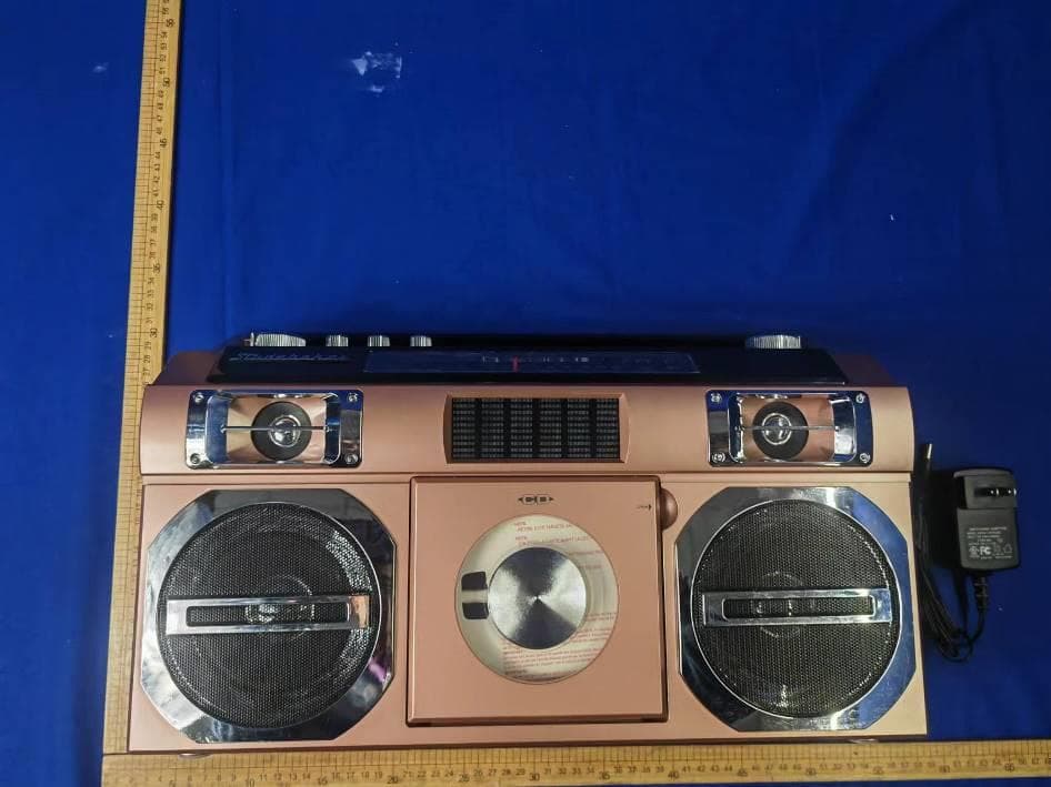
2BABY6361401USB
Apr 01, 2024PORTABLE BOOMBOX WITH BLUETOOTH, CD PLAYER, USB AND AM/FM RADIO
Equipment Class
DSS - Part 15 Spread Spectrum Transmitter
2BABY6961389N
Oct 08, 2023MIXER PLUS DJ/KARAOKE MEDIA CONTROLLER
Equipment Class
DSS - Part 15 Spread Spectrum Transmitter
2BABY696PJ1575
Sep 24, 2023HOME THEATER PROJECTOR & BLUETOOTH KARAOKE
Equipment Class
DSS - Part 15 Spread Spectrum Transmitter
2BABY696MET8024
Jul 02, 2023UNDERCABINET BLUETOOTH SPEAKER WITH FM RADIO
Equipment Class
DSS - Part 15 Spread Spectrum Transmitter
2BABY696PJ118
Jun 05, 2023Showtime Max 1080p Projector with Bluetooth
Equipment Class
DSS - Part 15 Spread Spectrum Transmitter