2BCGWEAP725WALLBE5000 Wall Plate Wi-Fi 7 Access Point
TP-LINK CORPORATION PTE.LTD.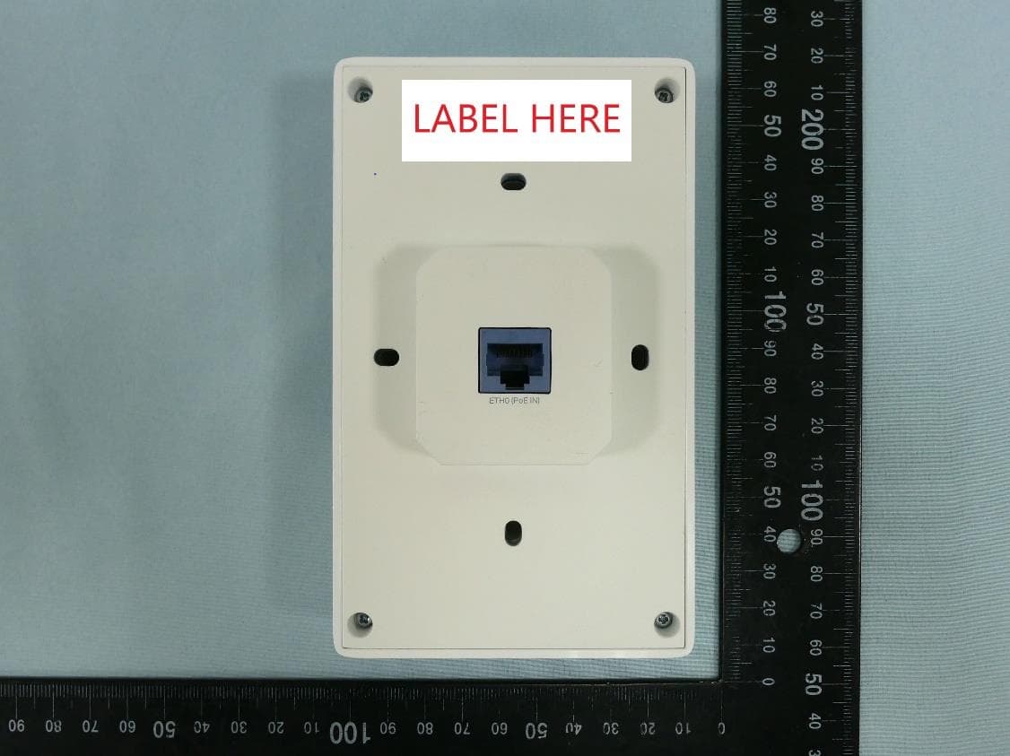
Click to zoom
Application Details
- Equipment Class
- NII - Unlicensed National Information Infrastructure TX
- Date of Grant
- Dec 01, 2024
- Application Purpose
- Original Equipment
- Date of Application
- Nov 26, 2024
- Equipment Note
- BE5000 Wall Plate Wi-Fi 7 Access Point
- Frequency Range
- 5250.00000000 - 5250.00000000
- Company
- TP-LINK CORPORATION PTE.LTD.
- Country
- Singapore
Documents & Files
Document Text
Text extracted from the exhibit documents filed with the FCC. Open a document above to read the original.
Users Manual
Before installation, be sure that you have the following items: A pre-installed wall junction box An RJ45 plug LED/Wi-Fi Button When the EAP is working in Standalone Mode and enabled with Wi-Fi Control, press the button to turn on/off both the Wi-Fi and LED. In the other cases, press the button to turn on/off the LED only. LAN Port A wired device can be connected to the LAN port via an Ethernet cable and access the network. RESET With the EAP powered on, press and hold the button for about 5 seconds until the LED flashes, then release the button. The EAP will restore to factory default settings. LED Indicator White On: Working normally/Initializing. For EAPs with dual-color LED: Normal power supply Orange On: For EAPs with dual-color LED: Low power supply Off: Working abnormally/Power off/LED is turned off. Flash: • Flash twice: Initialization is completed. • Flash once per second: The EAP is upgrading. • Flash quickly: The EAP is resetting or the Omada Controller is locating the EAP*. * When the Locate feature is activated in the Omada Controller, the EAP’s LED will flash quickly for 10 minutes to help you locate and identify the device. You can disable this feature manually to stop the device from flashing. • Sustained flash: The EAP is in isolated state.* * Only for EAPs supporting Omada Mesh. Screwdrivers A PoE switch Hardware Overview Quick Installation Guide Wireless Wall Plate Access Point Hardware Installation 3 Front Panel Rear Panel Pre-Installation Checklist 2 UPLINK+PoE Port / ETH0 (PoE IN) Port Connect to a PSE (Power Sourcing Equipment), such as a PoE switch, for both data transmission and power supply. The PSE shall comply with Power Source Class 2 (PS2) or Limited Power Source (LPS) of IEC 62368-1. The EAP can be mounted into a wall junction box. The junction box should be pre-installed with a running-in-wall Ethernet cable connected to a PoE switch. LAN Port RESET LED LED/Wi-Fi Button 5. Press the faceplate of the EAP back into position. Standard EU wall junction box86 mm wall junction box 4. Insert the enclosed screws and tighten them with a screwdriver to secure the mounting bracket. Note: • Do not over tighten the screws. • If the enclosed screws do not fit the junction box, use the screws attached to the junction box instead. 1 Note: The image may differ from the actual product. 1. Detach the faceplate of the junction box with a screwdriver (demonstrated with an 86 mm wall junction box). 2. Detach the faceplate of the EAP with a screwdriver. 3. Connect the Ethernet cable inside the junction box to an RJ45 plug. Then connect the cable to the PoE port at the rear panel. Position the Ethernet cable to ensure it is not strained. Note: For simplicity, we will take EAP230-Wall for example throughout the Guide. Standard US wall junction box LAN Port RESET LED/Wi-Fi Button Some common wall junction boxes: RESET LED/Wi-Fi Button LAN Ports Some common front panels: LED LED ©2024 TP-Link 7106511351 REV2.7.0 Business CommunityDownload CenterSetup Videos Set Up 4 Safety Information • Keep the device away from water, fire, humidity or hot environments. • Do not attempt to disassemble, repair, or modify the device. If you need service, please contact us. • Do not use the device where wireless devices are not allowed. • The PoE ports shall not be used to charge lithium batteries or devices supplied by lithium batteries. EU Declaration of Conformity TP-Link hereby declares that the device is in compliance with the essential requirements and other relevant provisions of directives 2014/53/EU, 2011 /65/EU and (EU) 2015/863. The original EU Declaration of Conformity may be found at https://www.tp-link.com/en/support/ce/ UK Declaration of Conformity TP-Link hereby declares that the device is in compliance with the essential requirements and other relevant provisions of the Radio Equipment Regulations 2017. The original UK Declaration of Conformity may be found at https://www.tp-link.com/support/ukca/ Choose a method to set up your EAPs: • Method 1: Standalone Mode Configure and manage EAPs separately (Convenient for a small network with only a few devices) • Method 2: Controller Mode Configure and manage EAPs in batches on a central platform, namely Omada Controller. Method 2: Controller Mode Notes: • A DHCP server (typically a gateway/router with the DHCP function enabled) is required to assign IP addresses to the EAPs and clients in your local network. • The Omada Controller must have network access to your Omada devices (the gateways/routers, switches, and EAPs) in order to find, adopt, and manage them. Omada Controller integrates Omada gateways/routers, switches, access points, and more for centralized management. Clients SwitchGateway/Router EAP EAP EAP EAP Omada Hardware/Software Controller Omada Cloud-Based Controller Or Controller 1. Get an Omada Controller ready. • Option 1: Omada Hardware Controller Obtain a Hardware Controller and refer to its Installation Guide to set it up. • Option 2: Omada Software Controller On a PC with Windows or Linux OS, download the Software Controller from https://www.tp-link.com/support/download/omada-software-controller/. Then run the file and follow the wizard to set up the Controller. Note: To manage your devices, the Software Controller needs to keep running on your PC. • Option 3: Omada Cloud-Based Controller Go to the Omada Portal (https://omada.tplinkcloud.com) and log in with your TP-Link ID. Then click + Add Controller to add a Cloud-Based Controller and set it up. 2. Launch the Controller, access your site, and go to the Devices page. 3. Now you can adopt and manage the EAPs. Tip: For the Omada Hardware/Software Controller, you are recommended to enable Cloud Access and bind it to your TP-Link ID. This enables you to remotely access and manage the Controller and Omada devices via Omada Portal (https://omada.tplinkcloud.com). For detailed configurations, refer to the User Guide of the Controller at our official website: https://www.tp-link…
Text truncated - open the document above for the full version.
Users Manual
© 2024 TP-Link 1910013239 REV1.4.0 Regulatory Compliance Wall Plate EAP For Class B EAP with no adapter: FCC Compliance Information Statement Product Name: Omada EAP Model Number: EAP225-Wall / EAP235-Wall / EAP615-Wall / EAP655-Wall / EAP725-Wall / EAP615GP-Wall / EAP673-Extender Responsible party: TP-Link Systems Inc. Address: 10 Mauchly, Irvine, CA 92618 Website: https://www.tp-link.com/us/ Tel: +1 626 333 0234 Fax: +1 909 527 6804 E-mail: [email protected] This equipment has been tested and found to comply with the limits for a Class B digital device, pursuant to part 15 of the FCC Rules. These limits are designed to provide reasonable protection against harmful interference in a residential installation. This equipment generates, uses and can radiate radio frequency energy and, if not installed and used in accordance with the instructions, may cause harmful interference to radio communications. However, there is no guarantee that interference will not occur in a particular installation. If this equipment does cause harmful interference to radio or television reception, which can be determined by turning the equipment off and on, the user is encouraged to try to correct the interference by one or more of the following measures: •Reorient or relocate the receiving antenna. •Increase the separation between the equipment and receiver. •Connect the equipment into an outlet on a circuit different from that to which the receiver is connected. •Consult the dealer or an experienced radio/ TV technician for help. This device complies with part 15 of the FCC Rules. Operation is subject to the following two conditions: 1) This device may not cause harmful interference. 2) This device must accept any interference received, including interference that may cause undesired operation. Any changes or modifications not expressly approved by the party responsible for compliance could void the user’s authority to operate the equipment. Note: The manufacturer is not responsible for any radio or TV interference caused by unauthorized modifications to this equipment. Such modifications could void the user’s authority to operate the equipment. FCC RF Radiation Exposure Statement: This equipment complies with FCC RF radiation exposure limits set forth for an uncontrolled environment. This device and its antenna must not be co-located or operating in conjunction with any other antenna or transmitter. “To comply with FCC RF exposure compliance requirements, this grant is applicable to only Mobile Configurations. The antennas used for this transmitter must be installed to provide a separation distance of at least 20cm from all persons and must not be colocated or operating in conjunction with any other antenna or transmitter.” We, TP-Link Systems Inc., has determined that the equipment shown as above has been shown to comply with the applicable technical standards, FCC part 15. There is no unauthorized change is made in the equipment and the equipment is properly maintained and operated. Issue Date: 2024-10-16 CE Mark Warning This is a class B product. In a domestic environment, this product may cause radio interference, in which case the user may be required to take adequate measures. OPERATING FREQUENCY (the maximum transmitted power) For EAP115-Wall: 2412MHz—2472MHz (20dBm) For EAP225-Wall / EAP230-Wall / EAP235-Wall / EAP615-Wall: 2412MHz—2472MHz (20dBm) 5150MHz—5250MHz (23dBm) For EAP650-Wall / EAP655-Wall / EAP725-Wall / EAP615GP-Wall / EAP673-Extender: 2400 MHz -2483.5 MHz (20dBm) 5150MHz—5250MHz (23dBm) 5250 MHz -5350 MHz (23dBm) 5470 MHz -5725 MHz (30dBm) EU Declaration of Conformity For EAP673-Extender, EAP615GP-Wall, and APs with adapters: TP-Link hereby declares that the device is in compliance with the essential requirements and other relevant provisions of directives 2014/53/EU, 2009/125/EC, 2011/65/EU and (EU)2015/863. For other APs: TP-Link hereby declares that the device is in compliance with the essential requirements and other relevant provisions of directives 2014/53/EU, 2011/65/EU and (EU)2015/863. The original EU Declaration of Conformity may be found at https://www.tp-link.com/en/ce. RF Exposure Information This device meets the EU requirements (2014/53/EU Article 3.1a) on the limitation of exposure of the general public to electromagnetic fields by way of health protection. The device complies with RF specifications when the device used at 20 cm from your body. National Restrictions For EAP225-Wall / EAP230-Wall / EAP235-Wall / EAP615-Wall / EAP650-Wall / EAP655-Wall / EAP725-Wall / EAP615GP-Wall / EAP673-Extender: Attention: This device may only be used indoors in all EU member states, EFTA countries and Northern Ireland. Frequency band: 5150 - 5250 MHz: Indoor use: Inside buildings only. Installations and use inside road vehicles and train carriages are not permitted. Limited outdoor use: If used outdoors, equipment shall not be attached to a fixed installation or to the external body of road vehicles, a fixed infrastructure or a fixed outdoor antenna. Use by unmanned aircraft systems (UAS) is limited to within the 5170 - 5250 MHz band. Frequency band: 5250 - 5350 MHz: Indoor use: Inside buildings only. Installations and use in road vehicles, trains and aircraft are not permitted. Outdoor use is not permitted. Frequency band: 5470 - 5725 MHz: Installations and use in road vehicles, trains and aircraft and use for unmanned aircraft systems (UAS) are not permitted. UKCA Mark UK Declaration of Conformity TP-Link hereby declares that the device is in compliance with the essential requirements and other relevant provisions of the Radio Equipment Regulations 2017. The original UK Declaration of Conformity may be found at https://www.tp-link.com/support/ukca National Restrictions Attention: This device may only be used indoors in Great Britain. UK Canadian Compliance Statement For EAP615-Wall / EAP655-Wall / EAP725-Wall / EAP615GP-Wall / EAP673-Extender: This device contains licence-exemp…
Text truncated - open the document above for the full version.
Attestation Statements
TP-LINK CORPORATION PTE.LTD. 7 Temasek Boulevard #29-03 Suntec Tower One, Singapore 038987 012423-17 rev2 Statement for 47 CFR section 2.911(d)(5)(i) TP-LINK CORPORATION PTE.LTD. certifies that as of the date of the application the equipment for which authorization is sought is not “covered” equipment 1 prohibited from receiving an equipment authorization pursuant to section 2.903 of the FCC rules. If the equipment for which the applicant seeks authorization is produced by any of the entities identified on the current Covered List, including affiliates or subsidiaries of the named companies, the applicant must include an explanation on why the equipment is not “covered” equipment. Additional Explanation: <N/A> Statement for 47 CFR section 2.911(d)(5)(ii) TP-LINK CORPORATION PTE.LTD. certifies that, as of the date of the filing of this application, the applicant ☐ - is /- is not identified on the Covered List as an entity producing “covered” equipment. Thank you, By: ____Sarah Wang__ (Signature 2 ) (Print name) Title: Compliance manager Company: TP-LINK CORPORATION PTE.LTD. PTE.LTD.) Telephone: +86 755 21534921 1 - The Commission’s Covered List is published by the Public Safety and Homeland Security Bureau and posted on the Commission’s website. This Covered List, which is periodically updated, identifies particular equipment, produced by particular entities, that constitutes “covered” equipment. https://www.fcc.gov/supplychain/coveredlist . 2 - Letters should be placed on appropriate letterhead.
Attestation Statements
U.S. AgentDesignationfor Serviceof Process (Applicantand U.S. Agentare SeparateParties) TO:AmericanCertificationBody, Inc. 313 Park Avenue Suite 300 Falls Church,VA 22046 ATTENTION:FCC Certification– Section2.911(d)(7)Information DesignatedU.S. Agent CompanyName:VISHTECLLC ContactName:Alan Graham StreetAddress:9888 W BelleviewAve Ste 2142 DenverCO 80123 City/Province/Zip:80123 TelephoneNo:(571)4007350 Email: [email protected] FRN #: 0033407131 This letter is to confirmthat we (“the DesignatedU.S. Agent ”) have acceptedthe responsibilityto act as the DesignatedU.S. Agent for Serviceof Processfor the limited purposeof compliancewith section47 CFR 2.911(d)(7)only and not for any other purpose,on behalfof theApplicantnoted below. U.S. AgentSignature: Date: 2023/8/28 Signedby (PrintedName/Title): The Applicant acknowledges that they must maintain an agent for no less than one year after terminating all marketing and importation OR the conclusion of any Commission- related proceeding involving the equipment. The applicant further acknowledges their responsibility to inform the FCC whenever the Designated U.S. Agent information above changes. Applicant Company name: TP-LINK CORPORATION PTE. LTD. Grantee Code: 2BCGW FRN #: 0034122556 Contact Name: Sarah Wang Street Address: 7 Temasek Boulevard #29-03 Suntec Tower One, Singapore 038987 City/Province/Zip: Singapore Telephone No: +65-97538388 Email: [email protected] Applicant Signature 1 : Date: 2023/8/28 Signed by (Printed Name/Title) S arah W ang 1 - Lettersshouldbe placedon appropriateletterhead.
Cover Letter(s)
Confidentiality Request Letter Federal Communications Commission Authorization and Evaluation Division FCC ID: 2BCGWEAP725WALL Confidentiality Request Pursuant to Sections 0.457 and 0.459 of the Commission’s Rules, we hereby request confidential treatment of information accompanying this application as outlined below: 1. Block Diagram 2. Schematics 3. Operational Description The above materials contain trade secrets and proprietary information not customarily released to the public. The public disclosure of these matters might be harmful to the applicant and provide unjustified benefits to its competitors. The applicant understands that pursuant to Rule 0.457, disclosure of this application and all accompanying documentation will not be made before the date of the Grant for this application. Sincerely, _________________ Name: Sarah Wang Position: Regulatory Compliance Manager Date: 2024-11-13
Cover Letter(s)
Declaration of Authorization We Name: TP-LINK CORPORATION PTE. LTD. Address: 7 Temasek Boulevard #29-03 Suntec Tower One, Singapore 038987 Declare that: Name Representative of agent: Marlin Chen Agent Company name: MRT Technology (Suzhou) Co., Ltd Address: D8 Building, Youxin Industrial Park, No.2 Tian'edang Rd., Wuzhong Economic Development Zone City: Suzhou Country: China is authorized to apply for Certification of the following product(s): Product: BE5000 Wall Plate Wi-Fi 7 Access Point FCC ID: 2BCGWEAP725WALL Model: EAP725-Wall Brand: tp-link Sincerely, _________________ Name: Sarah Wang Position: Regulatory Compliance Manager Date: 2024-11-13
Cover Letter(s)
Declaration of Conformity We Name: TP-LINK CORPORATION PTE. LTD. Address: 7 Temasek Boulevard #29-03 Suntec Tower One, Singapore 038987 Declare that: Product: BE5000 Wall Plate Wi-Fi 7 Access Point FCC ID: 2BCGWEAP725WALL Model: EAP725-Wall Brand: tp-link Product which bears the above FCC ID is also compliant with the FCC requirements for sDOC. And the sDOC procedure shall be carried out prior to marketing the device in the US. Sincerely, _________________ Name: Sarah Wang Position: Regulatory Compliance Manager Date: 2024-11-13
Cover Letter(s)
Non-SDR (Software Defined Radio) Cover Letter Refer to KDB 442812 D01 SDR apps Guide v02r03. The following six questions can be used for determining if a radio can elect to be, or must be an SDR. 1. Can the RF parameters of the device be altered through software? Yes - go to 2. No, not an SDR Yes 2. Can third parties not permitted by the Commission through specific filings modify, configure, or load different software, or make configuration settings to operate the device or host hardware radio frequency parameters (frequency range, modulation type, maximum output power or other radio parameters) in any other way than granted (or expected to be granted)? Yes, must be an SDR. No - go to 3. No 3. Is the device capable of operating in any other in any other way than granted, or will be, granted? Yes, - go to 4. No - go to 5. No 4. Is this a Part 15 client Device as defined in Section 15.202 (as opposed to a master device)? Yes, qualifies as a part 15 client devices - go to 5. No, must be an SDR. 5. Does the manufacturer elect SDR? Yes, elects to be an SDR. No, Not an SDR No Conclusion: According to the above questions reply, we can confirm this device (FCC ID: 2BCGWEAP725WALL & IC: 31152-EAP725WALL) must be a Non-SDR device. __________________ Name: Sarah Wang Position: Regulatory Compliance Manager Date: 2024-11-13
Cover Letter(s)
Declaration of Frequency Stability We TP-LINK CORPORATION PTE. LTD. ensure that the product (FCC ID: 2BCGWEAP725WALL, IC: 31152-EAP725WALL) meets e-CFR Title 47 section 15.407(g) & RSS-GEN Section 8.11 and KDB 789033 D02v02r01 frequency stability such that the emissions are maintained within the band of operation under all conditions of normal operation as specified in the user's manual. Sincerely, _________________ Name: Sarah Wang Position: Regulatory Compliance Manager Date: 2024-11-13
External Photos
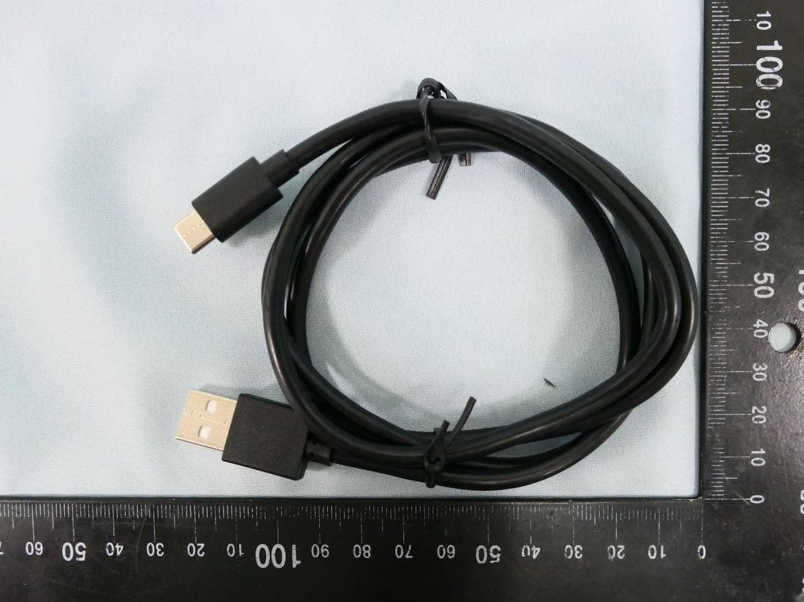
Report No.: 2408TW0107-UE 1 of 4 External Photograph (1) EUT Photo (2) EUT Photo Report No.: 2408TW0107-UE 2 of 4 (3) EUT Photo (4) EUT Photo Report No.: 2408TW0107-UE 3 of 4 (5) EUT Photo (6) EUT Photo Report No.: 2408TW0107-UE 4 of 4 (7) EUT Photo
ID Label/Location Info
A1 庄剧慈 2024-07-02 EAP725-Wall(US) 1.0壳体镭雕 工艺:镭雕 颜色:Pantone Cool Gray 6C 尺寸:44*24.9mm 尺寸:17.2*1.3mm 尺寸:51.3*1.5mm 86 5.0±0.3 1.0±0.3 1.1±0.3 4.6±0.3 Model:EAP725-Wall(US) Ver:1.0 S/N:XXXXXXXXXXXXX MAC:XX-XX-XX-XX-XX-XX SSID: TP-Link_2.4GHz_XXXXXX SSID: TP-Link_5GHz_XXXXXX 注: SN、MAC、SSID打印于26*15空白标贴,贴于标贴框。 MAC条形码由“xxxxxxxxxxxx”生成,文本按“xx-xx-xx-xx-xx-xx”格式打印 SN、MAC、SSID仅为示意,具体以机型实际/软件生成工具为准 16.2±0.5 31.2±0.8 16.2±0.5 BE5000 Wall Plate Wi-Fi 7 Access Point This device complies with part 15 of the FCC Rules. Operation is subject to the following two conditions:(1) This device may not cause harmful interference, and (2) this device must accept any interference received, including interference that may cause undesired operation. Model: EAP725-Wall PoE: 42.5-57V 0.95A 802.3at/bt Default Access: https://tplinkeap.net Username: admin Password: admin FCC ID: 2BCGWEAP725WALL IC: 31152-EAP725WALL MADE IN CHINA 深圳市联洲国际技术有限公司
Internal Photos
Report No.: 2408TW0107-UI 1 of 15 Internal Photograph (1) EUT Photo (2) EUT Photo Report No.: 2408TW0107-UI 2 of 15 (3) EUT Photo (4) EUT Photo Report No.: 2408TW0107-UI 3 of 15 (5) EUT Photo (6) EUT Photo Report No.: 2408TW0107-UI 4 of 15 (7) EUT Photo (8) EUT Photo Report No.: 2408TW0107-UI 5 of 15 (9) EUT Photo (10) EUT Photo Report No.: 2408TW0107-UI 6 of 15 (11) EUT Photo (12) EUT Photo Report No.: 2408TW0107-UI 7 of 15 (13) EUT Photo (14) EUT Photo Report No.: 2408TW0107-UI 8 of 15 (15) EUT Photo (16) EUT Photo Report No.: 2408TW0107-UI 9 of 15 (17) EUT Photo (18) EUT Photo Report No.: 2408TW0107-UI 10 of 15 (19) EUT Photo (20) EUT Photo Report No.: 2408TW0107-UI 11 of 15 (21) EUT Photo (22) EUT Photo Report No.: 2408TW0107-UI 12 of 15 (23) EUT Photo (24) EUT Photo Report No.: 2408TW0107-UI 13 of 15 (25) EUT Photo (26) EUT Photo Report No.: 2408TW0107-UI 14 of 15 (27) EUT Photo (28) EUT Photo Report No.: 2408TW0107-UI 15 of 15 (29) EUT Photo
RF Exposure Info
MRT Technology (Taiwan) Co., Ltd Report No.: 2408TW0107-U6 Phone: +886-3-3288388 Report Version 0.0 Web: www.mrt-cert.com Issue Date: 2024-11-06 Page Number: 1 of 12 RF Exposure Evaluation Declaration FCC ID : 2BCGWEAP725WALL Applicant : TP-LINK CORPORATION PTE. LTD. Application Type : Certification Product : BE5000 Wall Plate Wi-Fi 7 Access Point Model No. : EAP725-Wall Brand Name : tp-link Trademark : FCC Classification : Digital Transmission System (DTS) Unlicensed National Information Infrastructure (NII) Received Date : August 12, 2024 Test By : ( Owen Tsai ) Reviewed By : ( Paddy Chen ) Approved By : ( Chenz Ker) The test results relate only to the samples tested. The test results shown in the test report are traceable to the national/international standards through the calibration of the equipment and evaluated measurement uncertainty herein. The test report shall not be reproduced except in full without the written approval of MRT Technology (Taiwan) Co., Ltd. Report No.: 2408TW0107-U6 Page Number: 2 of 12 Revision History Report No. Version Description Issue Date Note 2408TW0107-U6 0.0 Draft Report 2024-11-06 Report No.: 2408TW0107-U6 Page Number: 3 of 12 CONTENTS Description Page 1. INTRODUCTION .................................................................................................................... 5 1.1. Scope .......................................................................................................................... 5 1.2. MRT Test Location ...................................................................................................... 5 2. PRODUCT INFORMATION .................................................................................................... 6 2.1. Feature of Equipment under Test ................................................................................ 6 2.2. Description of Available Antennas ............................................................................... 6 2.3. Device Classification ................................................................................................... 7 2.4. Applied Standards ....................................................................................................... 7 3. RF Exposure Evaluation ...................................................................................................... 8 3.1. Limits........................................................................................................................... 8 3.2. MPE Exemptions ......................................................................................................... 9 3.3. Test Result of RF Exposure Evaluation ......................................................................12 Report No.: 2408TW0107-U6 Page Number: 4 of 12 General Information Applicant TP-LINK CORPORATION PTE. LTD. Applicant Address 7 Temasek Boulevard #29-03 Suntec Tower One, Singapore 038987 Manufacturer TP-LINK CORPORATION PTE. LTD. Manufacturer Address 7 Temasek Boulevard #29-03 Suntec Tower One, Singapore 038987 Test Site MRT Technology (Taiwan) Co., Ltd Test Site Address No. 38, Fuxing Second Rd., Guishan Dist., Taoyuan City 333, Taiwan (R.O.C) MRT FCC Registration No. 291082 Test Facility / Accreditations 1. MRT facility is a FCC registered (Reg. No. 291082) test facility with the site description report on file and is designated by the FCC as an Accredited Test Firm. 2. MRT facility is an IC registered (MRT Reg. No. 21723) test laboratory with the site description on file at Industry Canada. 3. MRT Lab is accredited to ISO 17025 by the Taiwan Accreditation Foundation (TAF Cert. No. 3261) in EMC, Telecommunications and Radio testing for FCC (Designation Number: TW3261), Industry Canada, EU and TELEC Rules. Report No.: 2408TW0107-U6 Page Number: 5 of 12 1. INTRODUCTION 1.1. Scope Measurement and determination of electromagnetic emissions (EMC) of radio frequency devices including intentional and/or unintentional radiators for compliance with the technical rules and regulations of the Federal Communications Commission and the Innovation, Science and Economic Development Canada and Certification and Engineering Bureau. 1.2. MRT Test Location The map below shows the location of the MRT LABORATORY, its proximity to the Taoyuan City. These measurement tests were conducted at the MRT Technology (Taiwan) Co., Ltd. Facility located at No.38, Fuxing 2nd Rd., Guishan Dist., Taoyuan City 33377, Taiwan (R.O.C). Report No.: 2408TW0107-U6 Page Number: 6 of 12 2. PRODUCT INFORMATION 2.1. Feature of Equipment under Test 2.2. Description of Available Antennas Antenna Type Frequency Band (MHz) T X Paths Number of spatial streams Max Antenna Gain (dBi) Beamforming Directional Gain (dBi) CDD Directional Gain (dBi) For Power For PSD Wi-Fi Antenna Dipole 2412 ~ 2462 2 1 3.00 6.01 3.00 6.01 5150 ~ 5850 2 1 3.00 6.01 3.00 6.01 Bluetooth Antenna PIFA 2402 ~ 2480 1 1 1.5 -- -- -- Remark: 1. The EUT supports Cyclic Delay Diversity (CDD) mode, and CDD signals are correlated. If all antennas have the same gain, G ANT , Directional gain = G ANT + Array Gain, where Array Gain is as follows. • For power spectral density (PSD) measurements on all devices, Array Gain = 10 log (N ANT / N SS ) dB; • For power measurements on IEEE 802.11 devices, Array Gain = 0 dB for N ANT ≤ 4; 2. The EUT also supports Beam Forming mode, and the Beam Forming support 802.11n/ac/ax/be, not include 802.11a/b/g. BF Directional gain = G ANT + 10 log (N ANT ). Product Name BE5000 Wall Plate Wi-Fi 7 Access Point Model No. EAP725-Wall Brand Name tp-link Trademark Bluetooth Specification Bluetooth Mode: V5.2 Single mode Wi-Fi Specification 802.11a/b/g/n/ac/ax/be Power Supply 42.5-57V 0.95A 802.3at/bt Report No.: 2408TW0107-U6 Page Number: 7 of 12 3. The information as above is from the antenna report. Test Mode T X Paths CDD Mode Beamforming Mode 802.11b/g (DTS) 2 √ X 802.11n/ax/be (DTS) 2 √ √ 802.11a (NII) 2 √ X 802.11n/ac/ax/be (NII) 2 √ √ 2.3. Device Cla…
Text truncated - open the document above for the full version.
Test Report
MRT Technology (Taiwan) Co., Ltd Report No.: 2408TW0107-U4 Phone: +886-3-3288388 Report Version: 1.0 Web: www.mrt-cert.com Issue Date: 2024-11-20 Page Number: 1 of 537 FCC ID : 2BCGWEAP725WALL Applicant : TP-LINK CORPORATION PTE. LTD. Application Type : Certification Product : BE5000 Wall Plate Wi-Fi 7 Access Point Model No. : EAP725-Wall Brand Name : tp-link Trademark : FCC Classification : Unlicensed National Information Infrastructure (NII) FCC Rule Part(s) : Part15 Subpart E (Section 15.407) Received Date : August 12, 2024 Test Date : August 14, 2024 ~ October 28, 2024 MEASUREMENT REPORT Test By : ( Owen Tsai ) Reviewed By : ( Paddy Chen ) Approved By : ( Chenz Ker) The test results relate only to the samples tested. This equipment has been shown to be capable of compliance with the applicable technical standards as indicated in the measurement report and was tested in accordance with the measurement procedures specified in KDB 789033 D02v02r01. Test results reported herein relate only to the item(s) tested. The test report shall not be reproduced except in full without the written approval of MRT Technology (Taiwan) Co., Ltd. Report No.: 2408TW0107-U4 Page Number: 2 of 537 Revision History Report No. Version Description Issue Date Note 2408TW0107-U4 1.0 Original Report 2024-11-20 Valid Report No.: 2408TW0107-U4 Page Number: 3 of 537 CONTENTS Description Page 1. INTRODUCTION ..................................................................................................................... 7 1.1. Scope ........................................................................................................................... 7 1.2. MRT Test Location ....................................................................................................... 7 2. PRODUCT INFORMATION ..................................................................................................... 8 2.1. Equipment Description .................................................................................................. 8 2.2. Product Specification Subjective to this Report ............................................................. 8 2.3. Working Frequencies for this report .............................................................................. 9 2.4. Description of Available Antennas ............................................................................... 10 2.5. Test Mode ................................................................................................................... 11 2.6. Configuration of Test System ...................................................................................... 12 2.7. Test System Details .................................................................................................... 13 2.8. Description of Test Software ...................…
Text truncated - open the document above for the full version.
Contact Information
Applicant
sarah wang
Technical Contact
MRT Technology (Suzhou) Co., LtdRobin Wu
[email protected]86-512-66308358
D8 Building, Youxin Industrial Park, · Suzhou · China
Non-Technical Contact
MRT Technology (Suzhou) Co., LtdRobin Wu
[email protected]0512-66308358
Test Firm
MRT Technology (Taiwan) Co.,LtdChenz Ker
Technical Specifications
| # | Rule Parts | Frequency Range | Power Output |
|---|---|---|---|
| 5 | 15E | 5.25 GHz - 5.25 GHz | 96.20 mW |
Other Applications from TP-LINK CORPORATION PTE.LTD.
2BCGWWR3002X
Dec 05, 2024AX3000 Wi-Fi 6 Portable Router
Equipment Class
DTS - Digital Transmission System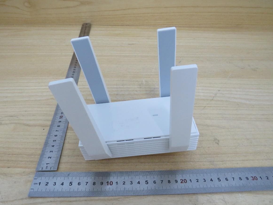
2BCGWEAP673EXTR
Oct 13, 2024AX5400 Wall Plate Wi-Fi 6 Extender
Equipment Class
NII - Unlicensed National Information Infrastructure TX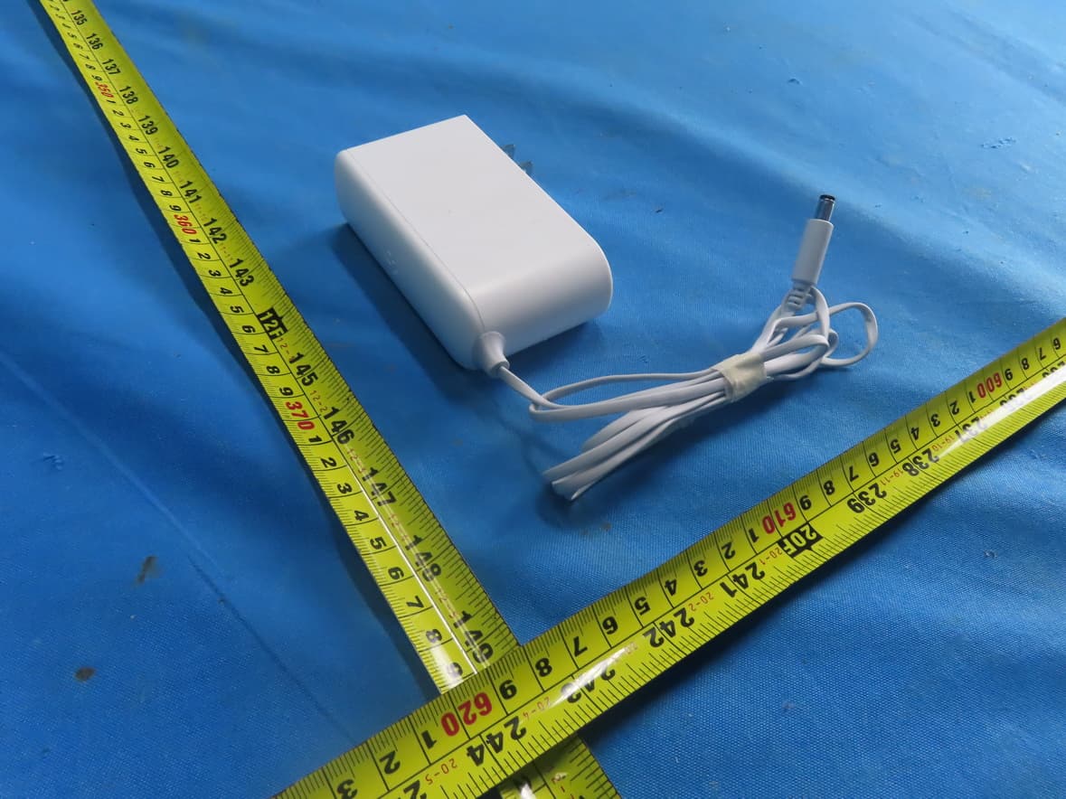
2BCGWH500
Sep 29, 2024Smart HomeBase
Equipment Class
NII - Unlicensed National Information Infrastructure TX
2BCGWAX72V2
Sep 28, 2024AX5400 Wi-Fi 6 Router
Equipment Class
NII - Unlicensed National Information Infrastructure TX
2BCGWBE25OD
Sep 24, 2024BE5000 Outdoor/Indoor Mesh Wi-Fi 7 Router
Equipment Class
NII - Unlicensed National Information Infrastructure TX