2BCGWTX35UPLUSAX1800 High Gain Wireless USB Adapter
TP-LINK CORPORATION PTE.LTD.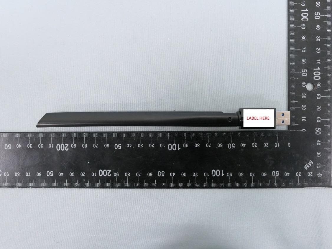
Click to zoom
Application Details
- Equipment Class
- NII - Unlicensed National Information Infrastructure TX
- Date of Grant
- Jun 25, 2024
- Application Purpose
- Original Equipment
- Date of Application
- Jun 25, 2024
- Equipment Note
- AX1800 High Gain Wireless USB Adapter
- Frequency Range
- 5745.00000000 - 5825.00000000
- Company
- TP-LINK CORPORATION PTE.LTD.
- Country
- Singapore
Documents & Files
Document Text
Text extracted from the exhibit documents filed with the FCC. Open a document above to read the original.
Users Manual
© 2024 TP-Link 1910013714 REV1.0.0 User Guide AX1800 High Gain Wireless USB Adapter Archer TX35U Plus Contents Chapter 1. About This Guide . . . . . . . . . . . . . . . . . . . . . . . . . . . . . . . . . . . .1 Chapter 2. Get to Know About Your Adapter. . . . . . . . . . . . . . . . . . . . .3 1. 1. Product Overview . . . . . . . . . . . . . . . . . . . . . . . . . . . . . . . . . . . . . . . . . . . . . . . . . . . . .4 1. 2. LED Status. . . . . . . . . . . . . . . . . . . . . . . . . . . . . . . . . . . . . . . . . . . . . . . . . . . . . . . . . . . .4 Chapter 3. Use the Adapter . . . . . . . . . . . . . . . . . . . . . . . . . . . . . . . . . . . . .5 2. 1. Install Driver. . . . . . . . . . . . . . . . . . . . . . . . . . . . . . . . . . . . . . . . . . . . . . . . . . . . . . . . . . .6 2. 2. Join a Wireless Network. . . . . . . . . . . . . . . . . . . . . . . . . . . . . . . . . . . . . . . . . . . . . . .6 2. 3. Uninstall Driver. . . . . . . . . . . . . . . . . . . . . . . . . . . . . . . . . . . . . . . . . . . . . . . . . . . . . . . .6 Chapter 4. Appendix: Troubleshooting . . . . . . . . . . . . . . . . . . . . . . . . . .7 1 About This Guide This guide is a complement to Quick Installation Guide. The Quick Installation Guide instructs you on quick installation, and this guide provides the product overview and detailed instructions for each steps. When using this guide, please notice that features available of the adapter may vary by model and software version. It may also vary by region or ISP. All images, steps, and descriptions in this guide are only examples and may not reflect your actual experience. Conventions In this guide, the following conventions are used: Convention Description Underlined Underlined words or phrases are hyperlinks. You can click to redirect to a website or a specific section. Teal Contents to be emphasized and texts on the web page are in teal, including the menus, items, buttons, etc. Note: Ignoring this type of note might result in a malfunction or damage to the device. Tips: Indicates important information that helps you make better use of your device. †Maximum wireless signal rates are the physical rates derived from IEEE Standard 802.11 specifications. Actual wireless data throughput , wireless coverage, and number of connected devices are not guaranteed and will vary as a result of network conditions, AP limitations, and environmental factors, including building materials, obstacles, volume and density of traffic, and AP location. ‡Use of Wi-Fi 6 (802.11ax), and features including OFDMA, MU-MIMO, and 1024- QAM require APs to also support the corresponding features. §Functionality of the adapter may be restricted on some operating systems and platforms. Please try to update the device’s driver for feature compatibility. △Use of WPA3 requires APs to also support the corresponding feature. Actual network speed may be limited by the rate of the product’s Ethernet WAN or LAN port, the rate supported by the network cable, Internet service provider factors and other environmental conditions. 2 More Info • The latest driver can be found at Download Center at https://www.tp-link.com/support. • The Quick Installation Guide can be found where you find this guide or inside the package of the router. • Specifications can be found on the product page at https://www.tp-link.com. • A TP-Link Community is provided for you to discuss our products at https://community.tp-link.com. • Our Technical Support contact information can be found at the Contact Technical Support page at https://www.tp-link.com/support. Chapter 1 Get to Know About Your Adapter This chapter introduces what the adapter can do and shows its appearance. This chapter contains the following sections: • Product Overview • LED Status 4 Chapter 1 Get to Know about Your Adapter 1. 1. Product Overview The latest Wi-Fi 6 standard guarantees extreme speeds, ultra-low latency, and uninterrupted connections. Archer TX35U Plus arms your PC with Wi-Fi 6 to ensure powerful, continuous signal reception, unlocking your Wi-Fi 6 router’s full potential. † • Boosted Throughput with MU-MIMO - Works with MU-MIMO routers, which provide simultaneous data streams, boosting throughput and efficiency. ‡ • Improved Security with WPA3 - The latest Wi-Fi security protocol provides enhanced protection in personal password safety.△ • Boost Wi-Fi Reception Range - The high gain antennas combine with Beamforming to concentrate Wi-Fi signals towards your router for better reception and reliable connections from far away. 1. 2. LED Status You can check the adapter’s working status by following the LED explanation table. Status Indication OnThe driver has been installed successfully. Off The driver is not installed. The adapter is not detected. 5 Chapter 1 Get to Know about Your Adapter Tips: If the LED is off, try these troubleshooting tips: 1. Check if the adapter is recognized and enabled or not. Refer to Appendix: Troubleshooting for detailed instructions. 2. Remove and reinsert the adapter. 3. Reinstall the software, if necessary. Chapter 2 Use the Adapter This chapter introduces how to install your adapter’s driver, use your adapter to join a wireless network, and uninstall your adapter in a Windows system. The adapter is equipped with a Setup Wizard, which can guide you through the installation process. This chapter includes the following sections: • Install Driver • Join a Wireless Network • Uninstall Driver 7 Chapter 2 Use the Adapter 2. 1. Install Driver 1. Insert the adapter into a USB port on your computer. 2. Go to My Computer or This PC. 3. Double click the TP-Link CD-ROM then run SetupInstall.exe to install driver Note: 1. If you cannot find the setup program, please download the driver at www.tp-link.com/support. 2. If an unknown publisher message pops up, select Yes to continue. 3. If Windows User Account Control requires admin credentials, type user name and password of your Windows administrator account. 2. 2…
Text truncated - open the document above for the full version.
Attestation Statements
TP-LINK CORPORATION PTE.LTD. 7 Temasek Boulevard #29-03 Suntec Tower One, Singapore 038987 012423-17 rev2 Statement for 47 CFR section 2.911(d)(5)(i) TP-LINK CORPORATION PTE.LTD. certifies that as of the date of the application the equipment for which authorization is sought is not “covered” equipment 1 prohibited from receiving an equipment authorization pursuant to section 2.903 of the FCC rules. If the equipment for which the applicant seeks authorization is produced by any of the entities identified on the current Covered List, including affiliates or subsidiaries of the named companies, the applicant must include an explanation on why the equipment is not “covered” equipment. Additional Explanation: <N/A> Statement for 47 CFR section 2.911(d)(5)(ii) TP-LINK CORPORATION PTE.LTD. certifies that, as of the date of the filing of this application, the applicant ☐ - is /- is not identified on the Covered List as an entity producing “covered” equipment. Thank you, By: ____Sarah Wang__ (Signature 2 ) (Print name) Title: Compliance manager Company: TP-LINK CORPORATION PTE.LTD. PTE.LTD.) Telephone: +86 755 21534921 1 - The Commission’s Covered List is published by the Public Safety and Homeland Security Bureau and posted on the Commission’s website. This Covered List, which is periodically updated, identifies particular equipment, produced by particular entities, that constitutes “covered” equipment. https://www.fcc.gov/supplychain/coveredlist . 2 - Letters should be placed on appropriate letterhead.
Attestation Statements
U.S. AgentDesignationfor Serviceof Process (Applicantand U.S. Agentare SeparateParties) TO:AmericanCertificationBody, Inc. 313 Park Avenue Suite 300 Falls Church,VA 22046 ATTENTION:FCC Certification– Section2.911(d)(7)Information DesignatedU.S. Agent CompanyName:VISHTECLLC ContactName:Alan Graham StreetAddress:9888 W BelleviewAve Ste 2142 DenverCO 80123 City/Province/Zip:80123 TelephoneNo:(571)4007350 Email: [email protected] FRN #: 0033407131 This letter is to confirmthat we (“the DesignatedU.S. Agent ”) have acceptedthe responsibilityto act as the DesignatedU.S. Agent for Serviceof Processfor the limited purposeof compliancewith section47 CFR 2.911(d)(7)only and not for any other purpose,on behalfof theApplicantnoted below. U.S. AgentSignature: Date: 2023/8/28 Signedby (PrintedName/Title): The Applicant acknowledges that they must maintain an agent for no less than one year after terminating all marketing and importation OR the conclusion of any Commission- related proceeding involving the equipment. The applicant further acknowledges their responsibility to inform the FCC whenever the Designated U.S. Agent information above changes. Applicant Company name: TP-LINK CORPORATION PTE. LTD. Grantee Code: 2BCGW FRN #: 0034122556 Contact Name: Sarah Wang Street Address: 7 Temasek Boulevard #29-03 Suntec Tower One, Singapore 038987 City/Province/Zip: Singapore Telephone No: +65-97538388 Email: [email protected] Applicant Signature 1 : Date: 2023/8/28 Signed by (Printed Name/Title) S arah W ang 1 - Lettersshouldbe placedon appropriateletterhead.
Cover Letter(s)
Declaration of Frequency Stability We [TP-LINK CORPORATION PTE. LTD.] ensure that the product (FCC ID: 2BCGWTX35UPLUS, IC: 31152-TX35UPLUS) meets e-CFR Title 47 section 15.407(g) & RSS-GEN Section 8.11 and KDB 789033 D02v02r01 frequency stability such that the emissions are maintained within the band of operation under all conditions of normal operation as specified in the user's manual. Sincerely, _________________ Name: Sarah Wang Position: Regulatory Compliance Manager Date: 2024-06-11
Cover Letter(s)
Confidentiality Request Letter Federal Communications Commission Authorization and Evaluation Division FCC ID: 2BCGWTX35UPLUS Confidentiality Request Pursuant to Sections 0.457 and 0.459 of the Commission’s Rules, we hereby request confidential treatment of information accompanying this application as outlined below: 1. Block Diagram 2. Schematics 3. Operational Description The above materials contain trade secrets and proprietary information not customarily released to the public. The public disclosure of these matters might be harmful to the applicant and provide unjustified benefits to its competitors. The applicant understands that pursuant to Rule 0.457, disclosure of this application and all accompanying documentation will not be made before the date of the Grant for this application. Sincerely, _________________ Name: Sarah Wang Position: Regulatory Compliance Manager Date: 2024-06-11
Cover Letter(s)
Declaration of Authorization We Name: TP-LINK CORPORATION PTE. LTD. Address: 7 Temasek Boulevard #29-03 Suntec Tower One, Singapore 038987 Declare that: Name Representative of agent: Marlin Chen Agent Company name: MRT Technology (Suzhou) Co., Ltd Address: D8 Building, Youxin Industrial Park, No.2 Tian'edang Rd., Wuzhong Economic Development Zone City: Suzhou Country: China is authorized to apply for Certification of the following product(s): Product: AX1800 High Gain Wireless USB Adapter FCC ID: 2BCGWTX35UPLUS Model: Archer TX35U Plus Brand: tp-link Sincerely, _________________ Name: Sarah Wang Position: Regulatory Compliance Manager Date: 2024-06-11
Cover Letter(s)
Declaration of Conformity We Name: TP-LINK CORPORATION PTE. LTD. Address: 7 Temasek Boulevard #29-03 Suntec Tower One, Singapore 038987 Declare that: Product: AX1800 High Gain Wireless USB Adapter FCC ID: 2BCGWTX35UPLUS Model: Archer TX35U Plus Brand: tp-link Product which bears the above FCC ID is also compliant with the FCC requirements for sDOC. And the sDOC procedure shall be carried out prior to marketing the device in the US. Sincerely, _________________ Name: Sarah Wang Position: Regulatory Compliance Manager Date: 2024-06-11
External Photos
Report No.: 2405TW0102-UE 1 of 3 External Photograph (1) EUT Photo (2) EUT Photo Report No.: 2405TW0102-UE 2 of 3 (3) EUT Photo (4) EUT Photo Report No.: 2405TW0102-UE 3 of 3 (5) EUT Photo (6) EUT Photo
Internal Photos
Report No.: 2405TW0102-UI 1 of 6 Internal Photograph (1) EUT Photo (2) EUT Photo Report No.: 2405TW0102-UI 2 of 6 (3) EUT Photo (4) EUT Photo Report No.: 2405TW0102-UI 3 of 6 (5) EUT Photo (6) EUT Photo Report No.: 2405TW0102-UI 4 of 6 (7) EUT Photo (8) EUT Photo Report No.: 2405TW0102-UI 5 of 6 (9) EUT Photo (10) EUT Photo Report No.: 2405TW0102-UI 6 of 6 (11) EUT Photo
RF Exposure Info
MRT Technology (Suzhou) Co., Ltd Report No.: 2405RSU001-U1 Phone: +86-512-66308358 Report Version: V01 Web: www.mrt-cert.com Issue Date: 2024-06-18 Template Version:0.0 1 of 64 SAR MEASUREMENT R EPORT FCC ID: 2BCGWTX35UPLUS Applicant: TP-LINK CORPORATION PTE. LTD. Product: AX1800 High Gain Wireless USB Adapter Model No.: Archer TX35U Plus Brand Name: tp-link FCC Rule Part(s): FCC 47 CFR Part 2.1093 Result: Complies Received Date: 2024-05-06 Test Date: 2024-05-18 ~ 2024-05-23 Reviewed By: Kevin Guo Approved By: Robin Wu The test results relate only to the samples tested. This equipment has been shown to be capable of compliance with the applicable technical standards as indicated in the measurement report and was tested in accordance with the measurement procedures specified in IEEE1528, KDB 447498 and KDB 865664. Test results reported herein relate only to the item(s) tested. The test report shall not be reproduced except in full without the written approval of MRT Technology (Suzhou) Co., Ltd. Report No.: 2405RSU001-U1 2 of 64 Revision History Report No. Version Description Issue Date Note 2405RSU001-U1 V01 Initial Report 2024-06-18 Valid Report No.: 2405RSU001-U1 3 of 64 CONTENTS Description Page 1. General Information ............................................................................................................................... 5 1.1. Applicant ...................................................................................................................................... 5 1.2. Manufacturer ................................................................................................................................ 5 1.3. Testing Facility ............................................................................................................................. 5 1.4. Product Information ...................................................................................................................... 6 1.5. Radio Specification under Test .................................................................................................... 7 1.6. Antennas Details .......................................................................................................................... 7 2. Summary of Test Result ........................................................................................................................ 8 2.1. Test Standards ............................................................................................................................. 8 2.2. Environment Condition ................................................................................................................. 8 2.3. RF Exposure Limits ...................................................................................................................... 8 2.4. Test Result Summary .................................................................................................................. 9 3. Specific Absorption Rate (SAR) .......................................................................................................... 10 3.1. Introduction ................................................................................................................................ 10 3.2. Definition .................................................................................................................................... 10 4. DASY6 Measurement System ............................................................................................................. 11 4.1. Introduction ................................................................................................................................ 11 4.2. DASY6 Measurement System Diagram .................................................................................... 11 4.3. System Components Details ...................................................................................................... 12 5. The SAR Measurement Procedure ..................................................................................................... 23 5.1. Measurement Process Diagram ................................................................................................ 23 5.2. Test Position Definition .............................................................................................................. 24 5.3. Test Procedure .......................................................................................................................... 27 6. System Verificaiton .............................................................................................................................. 30 6.1. SAR Tissue Check ..................................................................................................................... 30 6.2. SAR System Check ................................................................................................................... 33 7. Analysis and Results ........................................................................................................................... 35 7.1. Antenna Location ....................................................................................................................... 35 7.2. Conducted Power ...................................................................................................................... 36 7.3. SAR Test Results ....................................................................................................................... 41 8. Simultaneous Transmission Analysis ................................................................................................ 44 9. Measuring Instrument .......................................................................................................................... 47 10. Measurement Uncertainty.................................................................................................................... 48 An…
Text truncated - open the document above for the full version.
RF Exposure Info
Return Loss and Impedance Indicated By Head Tissue Meas. Items Original Value Current Value Deviation 5250MHz Return Loss(dB) -32.8 -33.68 2.68% Impedance 49.7Ω - 2.26jΩ 49.97Ω + 2.06jΩ 0.27Ω Real part 4.32Ω Imaginary part 5600MHz Return Loss(dB) -33.1 -28.85 -12.84% Impedance 51.8Ω + 1.33jΩ 46.88Ω - 1.38jΩ -4.92Ω Real part -2.71Ω Imaginary part 5750MHz Return Loss(dB) -23.4 -25.07 7.14% Impedance 51.7Ω + 6.68jΩ 46.93Ω + 4.42jΩ -4.77Ω Real part -2.26Ω Imaginary part Test Date: 2024/0 3/27
Test Report
Product Model: Archer TX35U Plus Manufacturer: TP-LINK CORPORATION PTE. LTD. Test Date: 2024.04.26 Tested By: Yu Sunli TP-LINK CORPORATION PTE. LTD. 7 Temasek Boulevard #29-03 Suntec Tower One, Singapore 038987 Index 1. Antenna Distribution ........................................................................................ 3 2. Electrical Characteristics ................................................................................ 3 3. Gain and Radiation Pattern ............................................................................. 4 3.1 Measurement Procedure ......................................................................................... 4 3.2 Test Setup ............................................................................................................... 5 3.3 S Parameter Test Data ............................................................................................ 6 3.4 Antenna Peak Gain ................................................................................................. 7 3.5 Antenna Radiation Pattern ....................................................................................... 7 Page 3 1. Antenna Distribution Archer TX35U Plus 2. Electrical Characteristics Ant1 Frequency 2400~2500 &5150~5895MHz Impedance 50Ohm Antenna Type Dipole Antenna Gain 1.00dBi@2400~2500MHz 2.00dBi@5150~5250MHz 2.00dBi@5250~5350MHz 2.00dBi@5470~5725MHz 2.00dBi@5725~5895MHz Radiation pattern Omni-Directional P/N 3101503839 Ant2 Frequency 2400~2500 &5150~5895MHz Impedance 50Ohm Antenna Type Dipole Antenna Gain 1.00dBi@2400~2500MHz 2.00dBi@5150~5250MHz 2.00dBi@5250~5350MHz 2.00dBi@5470~5725MHz 2.00dBi@5725~5895MHz Radiation pattern Omni-Directional P/N 3101503839 Page 4 3. Gain and Radiation Pattern 3.1 Measurement Procedure This measurement experiment adopted an antenna near-field measurement system, and the diagram of the measurement system was shown in Figure 3-1. The excitation signal was generated by the Keysight E5071C (300kHz-20GHz). Under the control of the central computer, the probe rotated in the θ direction, and the EUT rotated in the φ direction with the turntable. The probe sampling frame received and collected signals in the near-field range of the EUT. The software system which was controlled by the central computer completed the processing, output and display of the test data. Figure 3-1 The test site was a full anechoic chamber with a size of 3.0m×3.1m×2.97m, which was built by GTS Rayzone2800. All six surfaces of the anechoic chamber were pasted with absorbing materials. And the chamber was calibrated by the authoritative third-party lab every year. The antenna anechoic chamber measurement system adopted a 13-probe multi-probe system. The probe antennas were evenly distributed on the spherical surface surrounding the EUT, and theirs operating frequency was 600MHz~8.5GHz. During the measurement, the probe antennas were rotated in the θ direction under the control of the probe holder to sample the near-field data at the θ angle. At the same time, the EUT rotated with the turntable in the φ direction to sample the near field data at the φ angle. The sampling accuracy was 15°. The system diagram was shown in Figure 3-2. From the sampling results, the EUT's near-field test data of θ component, φ component and total component could be obtained. Page 5 Figure 3-2 Before the measurement, calibrated the vector network analyzer, and then connected the input end of each antenna to the output end of the vector network analyzer, and evenly the antennas to be measured. Test Equipment listed below: Equipments Model Manufacturer S/N Cali. Interval Cali. Due Date Chamber Rayzone2800 GTS(General Test System) MY5347043 5 12months 2025/01/15 Vector Network Analyzer E5071C Keysight MY46315238 24months 2026/03/13 GTS MaxSign100 Software V2.1 GTS(General Test System) / / / 3.2 Test Setup The test setup was shown in Figure 3-3, 3-4: Figure 3-3 Page 6 Figure 3-4 3.3 S Parameter Test Data Ant1 Ant2 Page 7 3.4 Antenna Peak Gain Frequency 2.45GHz 2400~2500MHz 5.2GHz 5150~5250MHz 5.3GHz 5250~5350MHz 5.6GHz 5470~5725MHz 5.8GHz 5725~5895MHz Ant1 MaxGain(dBi) 0.88 1.38 1.45 1.55 2.00 Ant2 MaxGain(dBi) 1.00 2.00 1.78 2.00 1.58 Ant1 Polarization/ Φ(°)/θ(°) Theta/120/-105 Theta/135/-75 Theta/135/-75 Theta/135/-135 Theta/135/-75 Ant2 Polarization/ Φ(°)/θ(°) Theta/150/-105 Theta/150/-90 Theta/150/-90 Theta/150/-105 Theta/165/-90 Max Gain(dBi) 1.00 2.00 2.00 2.00 2.00 3.5 Antenna Radiation Pattern Ant1 Ant2
Test Report
MRT Technology (Taiwan) Co., Ltd Report No.: 2405TW0102-U3 Phone: +86-512-66308358 Report Version: 1.0 Fax: +86-512-66308368 Issue Date: 2024-06-18 Web: www.mrt-cert.com Page Number: 1 of 25 FCC ID : 2BCGWTX35UPLUS APPLICANT : TP-LINK CORPORATION PTE. LTD. Application Type : Certification Product : AX1800 High Gain Wireless USB Adapter Model No. : Archer TX35U Plus Brand Name : tp-link FCC Classification : Unlicensed National Information Infrastructure (NII) FCC Rule Part(s) : Part 15.407 Test Procedure(s) : Master Device Client Device without radar detection Client Device with radar detection Received Date : May 3, 2024 Test Date : May 13, 2024 DFS MEASUREMENT REPORT Test By : ( Peter Syu ) Reviewed By : ( Paddy Chen ) Approved By : ( Chenz Ker) The test results relate only to the samples tested. This equipment has been shown to be capable of compliance with the applicable technical standards as indicated in the measurement report and was tested in accordance with the measurement procedures specified in Part 15.407. Test results reported herein relate only to the item(s) tested. The test report shall not be reproduced except in full without the written approval of MRT Technology (Taiwan) Co., Ltd. Report No.: 2405TW0102-U3 Page Number: 2 of 25 Revision History Report No. Version Description Issue Date Note 2405TW0102-U3 1.0 Original Report 2024-06-18 Valid Report No.: 2405TW0102-U3 Page Number: 3 of 25 CONTENTS Description Page 1. INTRODUCTION ..................................................................................................................... 5 1.1. Scope ........................................................................................................................... 5 1.2. MRT Test Location ....................................................................................................... 5 2. PRODUCT INFORMATION ..................................................................................................... 6 2.1. Equipment Description .................................................................................................. 6 2.2. Product Specification Subjective to this Report ............................................................. 6 2.3. Description of Available Antennas ................................................................................ 7 2.4. DFS Band Carrier Frequencies Operation .................................................................... 8 2.5. Test Mode .................................................................................................................... 8 3. DFS DETECTION THRESHOLDS AND RADAR TEST WAVEFORMS................................... 9 3.1. Applicability .................................................................................................................. 9 3.2. DFS Devices Requirements ........................................................................................ 10 3.3. DFS Detection Threshold Values ................................................................................. 11 3.4. Parameters of DFS Test Signals ................................................................................. 12 3.5. Conducted Test Setup ................................................................................................ 15 4. TEST EQUIPMENT CALIBRATION DATE ............................................................................ 16 5. TEST RESULT ...................................................................................................................... 17 5.1. Summary .................................................................................................................... 17 5.2. Radar Waveform Calibration ....................................................................................... 18 5.2.1. Calibration Setup ........................................................................................................ 18 5.2.2. Calibration Procedure ................................................................................................. 18 5.2.3. Cablibration Result ..................................................................................................... 19 5.3. Channel Loading Test Result ...................................................................................... 20 5.4. In-Service Monitoring for Channel Move Time, Channel Closing Transmission Time and Non-Occupancy Period Measurement ........................................................................................ 21 5.4.1. Test Limit .................................................................................................................... 21 5.4.2. Test Procedure Used .................................................................................................. 21 5.4.3. Test Result .................................................................................................................. 22 6. CONCLUSION ....................................................................................................................... 24 Appendix A : Test Setup Photograph ......................................................................................... 25 Appendix B : External Photograph ............................................................................................. 25 Appendix C : Internal Photograph .............................................................................................. 25 Report No.: 2405TW0102-U3 Page Number: 4 of 25 General Information Applicant TP-LINK CORPORATION PTE. LTD. Applicant Address 7 Temasek Boulevard #29-03 Suntec Tower One, Singapore 038987 Manufacturer TP-LINK CORPORATION PTE. LTD. Manufacturer Address 7 Temasek Boulevard #29-03 Suntec Tower One, Singapore 038987 Test Site MRT Technology (Taiwan) Co., Ltd Test Site Address No. 38, Fuxing Second Rd., Guishan Dist., Taoyuan City 333, Taiwan (R.O.C) MRT FCC Registration No. 291082 FCC Rule Part(s) Part 15.407 Test Fa…
Text truncated - open the document above for the full version.
Test Report
MRT Technology (Taiwan) Co., Ltd Report No.: 2405TW0102-U2 Phone: +886-3-3288388 Report Version: 1.0 Web: www.mrt-cert.com Issue Date: 2024-06-18 Page Number: 1 of 355 FCC ID : 2BCGWTX35UPLUS Applicant : TP-LINK CORPORATION PTE. LTD. Application Type : Certification Product : AX1800 High Gain Wireless USB Adapter Model No. : Archer TX35U Plus Brand Name : tp-link FCC Classification : Unlicensed National Information Infrastructure (NII) FCC Rule Part(s) : Part15 Subpart E (Section 15.407) Received Date : May 3, 2024 Test Date : May 6, 2024 ~ May 31, 2024 RF MEASUREMENT REPORT Test By : ( Owen Tsai ) Reviewed By : ( Paddy Chen ) Approved By : ( Chenz Ker) The test results relate only to the samples tested. This equipme…
Text truncated - open the document above for the full version.
Contact Information
Applicant
sarah wang
Technical Contact
MRT Technology (Suzhou) Co., LtdRobin Wu
[email protected]051266308358
D8 Building, Youxin Industrial Park, No.2 · Suzhou · China
Test Firm
MRT Technology (Suzhou) Co., Ltd.Mr. Marlin Chen
[email protected]+86-512-66308358
Technical Specifications
| # | Rule Parts | Frequency Range | Power Output |
|---|---|---|---|
| 4 | 15E | 5.75 GHz - 5.83 GHz | 44.20 mW |
Other Applications from TP-LINK CORPORATION PTE.LTD.
2BCGWWR3002X
Dec 05, 2024AX3000 Wi-Fi 6 Portable Router
Equipment Class
DTS - Digital Transmission System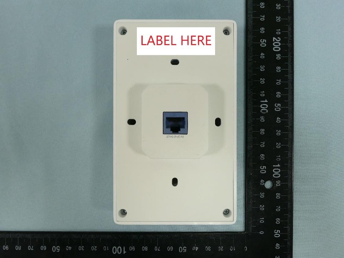
2BCGWEAP725WALL
Dec 01, 2024BE5000 Wall Plate Wi-Fi 7 Access Point
Equipment Class
NII - Unlicensed National Information Infrastructure TX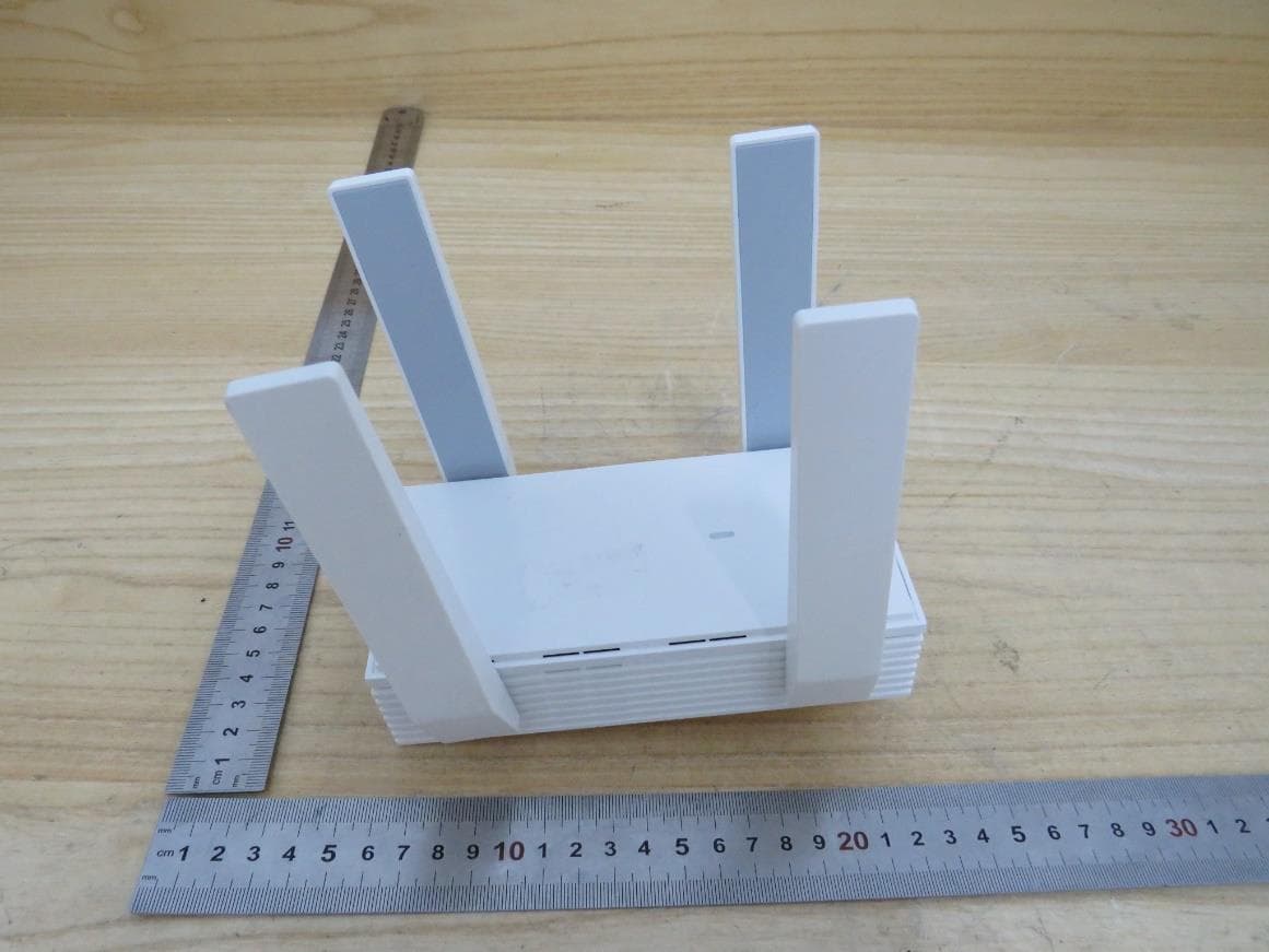
2BCGWEAP673EXTR
Oct 13, 2024AX5400 Wall Plate Wi-Fi 6 Extender
Equipment Class
NII - Unlicensed National Information Infrastructure TX
2BCGWH500
Sep 29, 2024Smart HomeBase
Equipment Class
NII - Unlicensed National Information Infrastructure TX
2BCGWAX72V2
Sep 28, 2024AX5400 Wi-Fi 6 Router
Equipment Class
NII - Unlicensed National Information Infrastructure TX