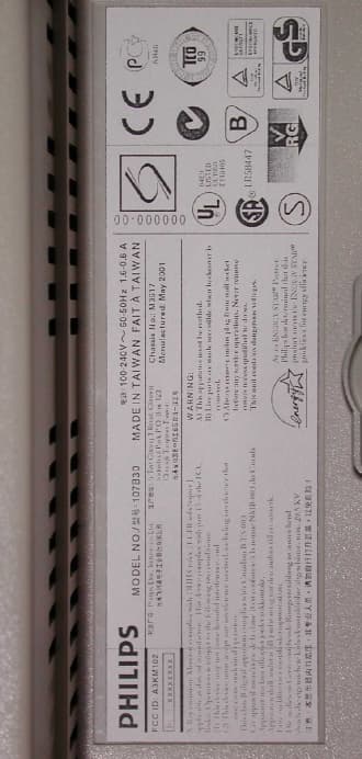
Click to zoom
Application Details
- Equipment Class
- JBP - Part 15 Class B Computing Device Peripheral
- Date of Grant
- Jun 14, 2001
- Application Purpose
- Original Equipment
- Date of Application
- Jun 14, 2001
- Equipment Note
- 17
- Country
- Taiwan
Documents & Files
Document Text
Text extracted from the exhibit documents filed with the FCC. Open a document above to read the original.
Users Manual
FCC ID: A3KM102 Exhibit 3 Installation and Operating Instruction FCC ID: A3KM102 FCC ID: A3KM102
Block Diagram
FCC ID: A3KM102 Exhibit-5 Block Diagram
External Photos
FCC ID: A3KM102 Exhibit 7 Photographs of EUT and Test Configuration Front View FCC ID: A3KM102 Rear View FCC ID: A3KM102 FCC ID Label FCC ID: A3KM102 Top View FCC ID: A3KM102 Side View FCC ID: A3KM102 Side View FCC ID: A3KM102 FCC ID: A3KM102 Shielding Plate FCC ID: A3KM102 PCB Layout FCC ID: A3KM102 PCB Layout FCC ID: A3KM102 PCB Layout FCC ID: A3KM102 PCB Layout FCC ID: A3KM102 Power Cord and I/F Cable
External Photos
FCC ID: A3KM102 Exhibit 7 Photographs of EUT and Test Configuration Front View FCC ID: A3KM102 Rear View FCC ID: A3KM102 FCC ID Label
ID Label/Location Info
FCC ID: A3KM102 Exhibit 2
Internal Photos
FCC ID: A3KM102 Top View FCC ID: A3KM102 Side View FCC ID: A3KM102 Side View FCC ID: A3KM102 FCC ID: A3KM102 Shielding Plate FCC ID: A3KM102 PCB Layout FCC ID: A3KM102 PCB Layout FCC ID: A3KM102 PCB Layout FCC ID: A3KM102 PCB Layout FCC ID: A3KM102 Power Cord and I/F Cable
Operational Description
FCC ID: A3KM102 Exhibit 4 Brief Description of Circuit Functions 1. Video pre-amplifier: The TDA4886 (7301) is a monolithic integrated RGB pre-amplifier for colour monitor system with I2C bus control and OSD mixer. In addition to bus control beam current limiting. The signal are amplified in order to drive output driver LM2439 (7701. Individual black level control (pin 17/20/23 0f 7301) with positive feedback for cut-off control. The RGB input signals with nominal signal amplitude of 0.7Vb-w are capacitively coupled (2308/2310/2311) into TDA4822_COSMIC IC (7302) from a 75 Ω (3301/3302/3303) source and output from pin19/21/23 of 7302 into TDA4886 actively clamped to an internal DC Voltage during signal black level by CLBL (pin 5) signal from deflection controller. A fast signal blanking is driven by CLBL signal. The input signal related to the internal reference black level can be simultaneous adjusted by contrast control via I2C bus with 6 bits DAC. For white point adjustment the individual for three channels gain control are driven by I2C bus with 6 bit DAC too. In the output stage the nominal input signal will be amplified to 2.8Vb-w output color signal at nominal contrast and maximum gain. Individual out put clamping is to set the reference black level of the signal output to a value which corresponds to the extend cut-off voltage of the CRT cathodes, all feedback reference are driven by I2C bus. The output signal from pre-amplifier R (pin19), G (pin16) and B (pin22) are sent to LM2439 to have around 40Vp-p amplitude, which are AC coupled to the CRT and need to be clamped to cut-off level. These are achieved by the black level clamp circuits 7721, 7722, 6721, 6722, 2724, 3723, 3724, 3725, 3726, 3727, 3786 for Red channel, the rest channel are identical to it and all of three channels are control by TDA4886 (R: pin 19, .G: pin16, B: pin 22). The OSD signal are inserted during fast blanking active period, the OSD and fast blanking signal are generated by OSD IC MTV018-27. Actually, the COSMIC IC TDA4822 just only by-pass the RGB video signal and it will enhance the gain of video around 40% while allp the lighfram function. 2.0. Micro controller: The micro controller WT62P2(7801) is monitor micro controller with DDC interface to the PC host. The internal built in hardware can detect sync. presence for the VESA DPMS standard of various display mode with separated (pin 40: H 41; V) . The output pin33/34 can be used to control the video and deflection function of the monitor. Besides to control two bus driven IC TDA4841 and TDA4886 via I2C bus , micro controller output still handle the rest function as V-DC shift, rotation, brightness, power management , degaussing, LED color, H-unlock detector, ABL, s-cap switch, H-Dc shift, and H-linearity. After alignment the data are stored at EEPROM 7804. 3. Deflection controller: The TDA4841 is a high performance and efficient solution for autosync monitors. All functions are controllable by I2C bus. TDA4841 provides synchronization processing, FCC ID: A3KM102 horizontal and vertical with full autosync capability, it provides extended function e.g. as a flexible B+ control. and extensive set of geometry control facilities. The HSYNC (pin15) is the input for horizontal synchronization signal which can be TTL separate or composite sync with positive or negative polarity. The horizontal oscillator capacitor at HCAP (pin 29) for optimum jitter performance the value of 10nF must not be changed. The given value is widely synchronised from 30KHz to 86KHz. PLL1 phase detector compares the middle of horizontal sync with a fixed point on the oscillator sawtooth voltage. The PLL1 loop filter is connected to HPLL1 (pin 26). Via register HPOS the I2C bus allows a linear adjustment of the relative phase between horizontal sync and oscillator sawtooth (in PLL1 loop). Via registers HPARAL and HPINBAL correction of pin unbalance and parallelogram is done by modulating the phase between oscillator sawtooth and horizontal flyback (in loop PLL2). The PLL2 phase detector is similar to PLL1 detector and compares the line flyback pulse at HFLB (pin 1) with the oscillator sawtooth voltage. The control currents are independent of horizontal frequency. The PLL2 detector thus compensates for the delay in the external horizontal deflection circuit by adjusting the phase of HDRV (pin8) output pulse. EWDRV (pin 11) provides a complete EW drive waveform. The components horizontal pincushion, size, corner correction, and trapezium correction are controlled by the registers HPIN, HSIZE, HCOR and HTRAP. The VSYNC (pin14) is the input for vertical synchronization signal it can be TTL separate or extract from composite sync. with positive or negative polarity. The widely synchronization range from 50 to 160Hz. The amplitude of the differential output currents at VOUT1 and VOUT2 can be adjusted via register VSIZE. Register VPOS provides a DC shift at the sawtooth output VOUT1 and VOUT2 (pin 13 and pin 12) and the EW drive output EWDRV (pin11) in such a way, that the whole picture moves vertically while maintaining the correct geometry. The horizontal moiré (also known as video moiré) can be cancelled by controlling register HMOIRE and cancelled vertical moiré (scan moiré) by controlling register VMOIRE. The B+ function block cab be used for buck converter in feed forward mode. It provides a frequency independent pulse width to control the deflection circuit. 4. Horizontal deflection: The horizontal output signal 7501 pin 8 (limited at very low amplitude around 1.4Vp-p) directly fed to driver stage 7605, after boost to about 80Vp-p and amplifies current drive capability it drives output transistor 7606 to reach expected deflection current. The horizontal linearity correction circuits is composed by 4 segment S-cap. switch (7262, 7263, 7264, 7266) and one controllable linearity coil 5601 to get optimised linearity The B+ control output signal is modulated with geometry control and size con…
Text truncated - open the document above for the full version.
Test Report
FCC ID: A3KM102 Exhibit 6 Statement of Data Measured and Test Data 1. General Information of EUT The EUT, 17” color monitor : Model No. : 107B30 FCC ID : A3KM102 Brand : Philips The color monitor automatically scans horizontal frequencies between 30KHz and 86KHz , and vertical frequencies between 60Hz and 120Hz. This color monitor displays sharp and brilliant images of text and graphics with a maximum resolution up to 1600x1200 pixels. . The monitor has 14 factory-preset modes as indicated in the following table: 2. Test Equipment and Procedure Test was performed by: PHILIPS ELECTRONICS INDUSTRIES (TAIWAN) LTD. CONSUMER ELECTRONICS DIVISION EMI - LAB 5, Tze Chiang 1 Road, Chungli Industrial Park P.O. Box 123, Chungli, Taoyuan, Taiwan R. O. C. Tel : 886-3-4549862 Fax : 886-3-4549887 Internet: [email protected] The test was performed in accordance with ANSI C63.4-1992, “AMERICAN NATIONAL STANDARD FOR MEASUREMENT OF RADIO-NOISE EMISSION FROM LOW- VOLTAGE ELECTRICAL AND ELECTRONIC EQUIPMENT IN THE RANGE OF 9KHz TO 40GHz” Resolution H-FrequencyV-FrequencyRemark M01 720 X 400 31.5KHZ 70Hz Non-interlaced M02 640 X 480 31.5KHZ 60Hz Non-interlaced M03 800 X 600 46.8KHz 75Hz Non-interlaced M04 800 X 600 53.7KHz 85Hz Non-interlaced M05 1024 X 768 60.0KHz 75Hz Non-interlaced M06 1024 X 768 68.7KHz 85Hz Non-interlaced M07 1280 X 1024 80.0KHz 75Hz Non-interlaced M08 640 x 480 43.3KHz 85Hz Non-interlaced FCC ID: A3KM102 Test equipment used for line Conducted and Radiated emissions as following. All equipment were calibrated according to ANSI C63.4-1992 and ISO-9000 requirement unless otherwise specified. Test Equipment Model No. Serial No. Next Calibrate Spectrum HP8568B 2928A40640 7/25/2001 RF Preselector HP85685A 2620A00338 7/25/2001 QP Adapter HP85650A 2811A01324 7/25/2001 EMI Receiver HP85460A 3441A00199 9/05/2001 EMI Receiver R & S ESVS30 8419977/066 5/28/2002 Biconical Antenna EMCO 3110B 3222 4/27/2002 Biconical Antenna EMCO 3110B 3224 4/27/2002 Log-Periodic Antenna EMCO 3146A 1424 4/27/2002 Log-Periodic Antenna EMCO 3146A 1425 4/27/2002 LISN EMCO 3825/2 9311-2153 11/27/2001 LISN EMCO 3825/2 9311-2154 11/27/2001 Turn Table EMCO 1060 1068 11/27/2001 Antenna Tower EMCO 1050 1113 11/27/2001 RF Cable M17/75-RG214-NE N/A 11/27/2001 Computer HP9000/300 2614A78610 N/A Printer HP2225A 2728S02586 N/A Plotter HP7440A 2539A40856 N/A Traceability to R.O.C. and international standards is assured by using calibrated all equipment. For system measurement, the EUT “107B30” was connected to: The system was configured for testing in a typical fashion ( as a customer would normally use it ) according to ANSI C63.4-1992, please see the photographs for detail. Both conducted and radiated testing were performed according to the procedure in ANSI C63.4-1992. Conducted testing was performed in screen room and radiated testing was performed in open site at an antenna to EUT distance of 3-meter on horizontal and vertical polarization. First, pre-scan all modes in screen room then select 2 higher modes (worst case) were tested and reported. Item Model No. Serial No. FCC ID 1. Computer SCENIC 661P III 171617 HSSSCENIC6511 2. Keyboard S26381-K252 H0S02 HSS01TSTK252 3. Mouse Logitech M-S48A LZA95220043 JNZ201213 4. Printer HP 2225C 3123S97227 DSI6XU2225 5. Modem USRobotics 268 0002680559278575CJE-0318 6. Vide Card S3 Trio 3D/2X C10N091416 FCC Logo FCC ID: A3KM102 The line conductive interference was tested with 110VAC and 220VAC receptively. Unshielded power cord was used during test. Tested and reported modes as following: Report No. Resolution Frequencies I/F Cable EMI01-017 1280x1024 80.0KHz/75Hz D-sub EMI01-017A 1600x1200 75.0KHz/60Hz D-sub 3. Test Program and Test Results Set up the EUT and all peripherals as chapter 6 of ANSI C63.4-1992 for AC power line conducted emissions testing and radiated emissions testing. Turn on the power of EUT and all peripherals, select an appropriate displaying mode using the “setup” software. Then run an EMI test program “HTEST.EMI” as a basic software to execute the EUT operating under test. Step 1 : Run the “HTEST.EMI” on personal computer then sends “H” character to monitor continuously until full screen. Step 2 : Personal computer sends a complete line of continuously repeating “H” to HP 2225C printer. Step 3 : Personal computer sends a file of “H” pattern to floppy disk then read a file of “H” pattern from floppy disk. Step 4 : Personal computer sends a file of “H” pattern to hard disk then read a file of “H” pattern from hard disk. Step 5 : Personal computer sends a file of “H” patter to USRobotics 268 modem. Step 6 : Return to step 1 All data in this report are “PEAK” value within 15dB margin unless otherwise noted. The radiated (open site) data has included antenna and cable factors, sample calculation: Final Value (dBμv/m) = Reading (dBuv) + Antenna Factor (dB) + Cable Loss (dB) The measured data of radiated RF interference at open site and line conducted interference as attached. FCC ID: A3KM102
Test Report
FCC ID: A3KM102 FCC TEST REPORT Report No. : EMI01-017 Tested Date: June/03/2001 Test Performed By Philips Electronics Industries (Taiwan) Ltd. Business Electronics EMC Lab. No. 5, Tze Chiang 1 Road, Chungli, Taoyuan, Taiwan, R.O.C. Tel.: + 886-3-454-9862 Fax.: +886-3-454-9887 Manufacturer : Philips Business Electronics Tested System: 1. EUT : Philips 107B30 color monitor s/n: TY0104017 FCC ID : A3KM102 2. Computer : SCENIC 661P III s/n: 171617 FCC ID : HSSSCENIC6511 3. Keyboard : S26381-K252 s/n: H0S02 FCC ID : HSS01TSTK252 4. Mouse : M-S48A s/n: LZA95220043 FCC ID : JNZ201213 5. Modem : USRoboties 268 s/n: 002680559278575 FCC ID : CJE-0318 6. Printer : HP2225C s/n: 3123S97227 FCC ID : DSI6XU2225 7. Video Card : S3 Trio 3D/2X s/n: C10N091416 FCC ID : FCC Logo Note: Test was performed in according with FCC measurement procedure ANSI C63.4-1992 “AMERICAN NATIONAL STANDARD FOR MEASUREMENT OF RADIO-NOISE EMISSION FROM LOW-VOLTAGE ELECTRONIC EQUIPMENT IN THE RANGE OF 9KHz TO 40GHz” Monitor was connected to floor mounted AC outlet. 80.0KHz mode (1280x1024/75Hz) was tested. D-sub I/F cable with two ferrite cores was used. Non-shield power cord was used during test. The test equipment used for testing please refer to the list as attached. Deviation: None Radiated RF Level – Peak Value Frequency Horizontal Vertical FCC/B Limit (MHz) (dBuv/m) (dBuv/m) (dBuv/m) 47.18 26.08 32.28 40.0 60.68 23.53 26.03 40.0 67.43 26.81 29.31 40.0 74.18 25.62 23.52 40.0 114.65 25.9 29.0 43.5 134.85 26.15 27.65 43.5 161.84 27.66 29.96 43.5 229.26 33.38 32.48 46.0 269.69 35.7 34.8 46.0 330.08 30.32 31.42 46.0 350.62 31.1 31.5 46.0 FCC ID: A3KM102 357.36 33.2 33.5 46.0 364.1 33.4 33.3 46.0 377.58 32.5 32.7 46.0 384.32 32.12 31.62 46.0 397.8 33.52 32.62 46.0 404.54 36.76 34.56 46.0 411.28 33.73 33.43 46.0 418.02 34.01 34.11 46.0 424.76 37.1 36.4 46.0 431.5 35.36 33.86 46.0 444.98 35.98 33.18 46.0 465.21 37.66 37.26 46.0 478.71 35.28 36.42 46.0 485.45 34.72 34.92 46.0 492.18 36.74 37.04 46.0 498.92 35.86 37.06 46.0 512.42 38.69 35.39 46.0 519.14 39.05 37.75 46.0 532.63 37.43 38.03 46.0 546.12 34.88 35.98 46.0 559.61 36.64 35.14 46.0 566.35 36.18 35.48 46.0 579.84 39.46 38.86 46.0 586.58 39.14 38.94 46.0 600.07 34.8 35.9 46.0 606.81 36.12 35.52 46.0 627.03 37.68 38.28 46.0 633.77 36.76 37.16 46.0 647.25 37.58 38.18 46.0 654.0 36.97 37.77 46.0 694.44 39.15 39.85 46.0 Spectrum Analyzer Setting: RBW: 100KHz VBW: 100KHz Quasi-peak Values were taken with Rohde & Schwarz ESVS 30 EMI test receiver. Radiated RF Level – QP Value Frequency Horizontal Vertical FCC/B Limit (MHz) (dBuv/m) (dBuv/m) (dBuv/m) 471.97 38.62 38.92 46.0 539.38 37.75 38.85 46.0 The spectrum was scanned from 30MHz to 1000MHz and the significant emissions were recorded. Test distance between device under test and receiving antenna was 3-meter. Sample of calculation: Final value (dBuv/m) = Antenna Factor (dB) + Cable Loss (dB) + Reading value (dBuv/m) Tested by: C.C.Wu Checked by: K.J.Hsu EMI Technician MC Engineer NVLAP Signatory FCC ID: A3KM102 FCC ID: A3KM102 FCC ID: A3KM102 FCC ID: A3KM102 FCC TEST REPORT Report No. : EMI01-017A Tested Date: June/04/2001 Test Performed By Philips Electronics Industries (Taiwan) Ltd. Business Electronics EMC Lab. No. 5, Tze Chiang 1 Road, Chungli, Taoyuan, Taiwan, R.O.C. Tel.: + 886-3-454-9862 Fax.: +886-3-454-9887 Manufacturer : Philips Business Electronics Tested System: 1. EUT : Philips 107B30 color monitor s/n: TY0104017 FCC ID : A3KM102 2. Computer : SCENIC 661P III s/n: 171617 FCC ID : HSSSCENIC6511 3. Keyboard : S26381-K252 s/n: H0S02 FCC ID : HSS01TSTK252 4. Mouse : M-S48A s/n: LZA95220043 FCC ID : JNZ201213 5. Modem : USRoboties 268 s/n: 002680559278575 FCC ID : CJE-0318 6. Printer : HP2225C s/n: 3123S97227 FCC ID : DSI6XU2225 7. Video Card : S3 Trio 3D/2X s/n: C10N091416 FCC ID : FCC Logo Note: Test was performed in according with FCC measurement procedure ANSI C63.4-1992 “AMERICAN NATIONAL STANDARD FOR MEASUREMENT OF RADIO-NOISE EMISSION FROM LOW-VOLTAGE ELECTRONIC EQUIPMENT IN THE RANGE OF 9KHz TO 40GHz” Monitor was connected to floor mounted AC outlet. 75.0KHz mode (1600x1200/60Hz) was tested. D-sub I/F cable with two ferrite cores was used. Non-shield power cord was used during test. The test equipment used for testing please refer to the list as attached. Deviation: None Deviation: None Radiated RF Level – Peak Value Frequency Horizontal Vertical FCC/B Limit (MHz) (dBuv/m) (dBuv/m) (dBuv/m) 42.33 25.78 31.78 40.0 63.51 25.92 27.82 40.0 70.57 25.08 26.38 40.0 84.68 29.95 28.45 40.0 120.02 27.0 28.6 43.5 183.45 29.87 27.97 43.5 225.8 33.32 31.82 46.0 239.93 35.0 33.5 46.0 246.98 34.28 33.28 46.0 FCC ID: A3KM102 324.59 31.3 30.4 46.0 338.72 31.93 30.13 46.0 345.77 33.0 31.6 46.0 359.89 32.1 31.4 46.0 366.95 32.6 32.0 46.0 402.18 35.52 37.92 46.0 409.27 34.3 35.4 46.0 416.33 33.09 32.69 46.0 423.38 34.77 33.47 46.0 437.5 34.31 33.31 46.0 444.54 38.08 35.98 46.0 451.6 35.94 34.54 46.0 458.66 35.81 36.01 46.0 465.71 38.58 39.38 46.0 472.77 35.55 35.25 46.0 479.83 33.96 33.06 46.0 486.89 36.28 33.98 46.0 500.98 37.0 35.0 46.0 508.05 38.86 37.52 46.0 515.1 34.92 33.72 46.0 529.22 34.71 35.81 46.0 543.34 37.97 35.07 46.0 550.39 37.7 35.0 46.0 564.5 37.16 36.66 46.0 571.56 34.92 35.22 46.0 578.62 35.94 34.74 46.0 585.68 36.23 35.33 46.0 599.78 37.5 35.3 46.0 628.02 36.82 35.78 46.0 Spectrum Analyzer Setting: RBW: 100KHz VBW: 100KHz Quasi-peak Values were taken with Rohde & Schwarz ESVS 30 EMI test receiver. Radiated RF Level – QP Value Frequency Horizontal Vertical FCC/B Limit (MHz) (dBuv/m) (dBuv/m) (dBuv/m) 606.84 38.72 35.42 46.0 The spectrum was scanned from 30MHz to 1000MHz and the significant emissions were recorded. Test distance between device under test and receiving antenna was 3-meter. Sample of calculation: Final value (dBuv/m) = Antenna Factor (dB) + Cable Loss (dB) + Reading value (dBuv/m) Tested by: C.C.Wu Checked by: K.J.Hsu EMI Technician MC Engineer NVLAP Signatory FCC ID: A3KM102 FCC ID: A3KM102 FCC ID…
Text truncated - open the document above for the full version.
Test Setup Photos
FCC ID: A3KM102 Conducted Emissions Test FCC ID: A3KM102 Conducted Emissions Test FCC ID: A3KM102 Radiated Emissions Test FCC ID: A3KM102 Radiated Emissions Test
Contact Information
Applicant
Ronnie Yang(Manager, Safety/DEV)
Technical Contact
Safety & Compliance ConsultingRichard Mullen
[email protected](973) 728-5141
29 Sweetman Lane · West Milford, New Jersey · United States
Test Firm
Philips Electronics Industries (Taiwan) Ltd.Ronnie Yang
Technical Specifications
| # | Rule Parts | Frequency Range | Power Output |
|---|---|---|---|
| 2 | 15B | - | - |
Other Applications from Philips Electronics Industries (Taiwan) Ltd
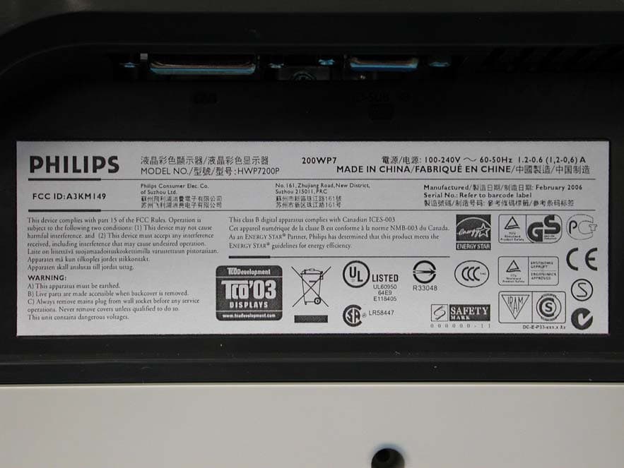
A3KM149
Mar 16, 200620� LCD Monitor
Equipment Class
JBP - Part 15 Class B Computing Device Peripheral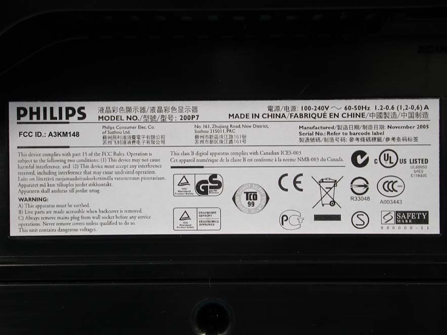
A3KM148
Dec 15, 200520
Equipment Class
JBP - Part 15 Class B Computing Device Peripheral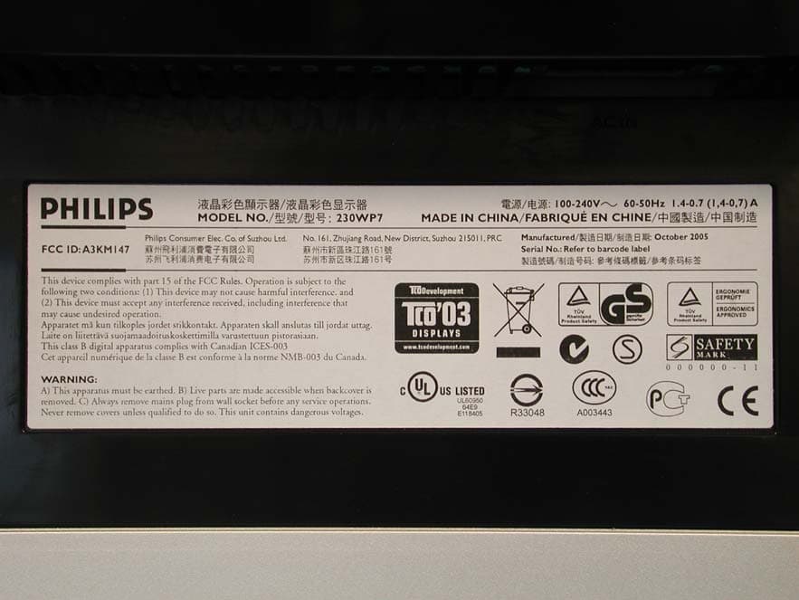
A3KM147
Nov 17, 2005LCD Monitor
Equipment Class
JBP - Part 15 Class B Computing Device Peripheral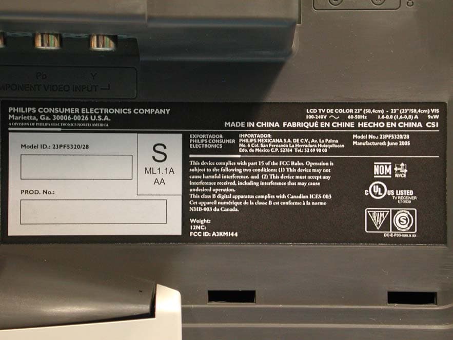
A3KM144
Jul 19, 2005LCD TV
Equipment Class
JBP - Part 15 Class B Computing Device Peripheral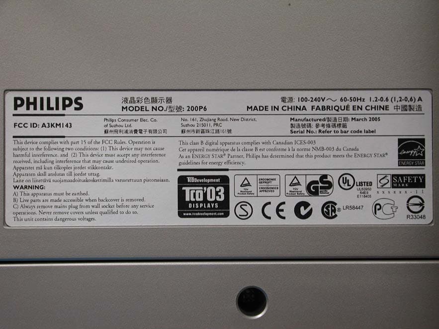
A3KM143
Apr 18, 2005Display Color Monitor
Equipment Class
JBP - Part 15 Class B Computing Device Peripheral