A3KM10417" Color LCD Monitor
Philips Electronics Industries (Taiwan) Ltd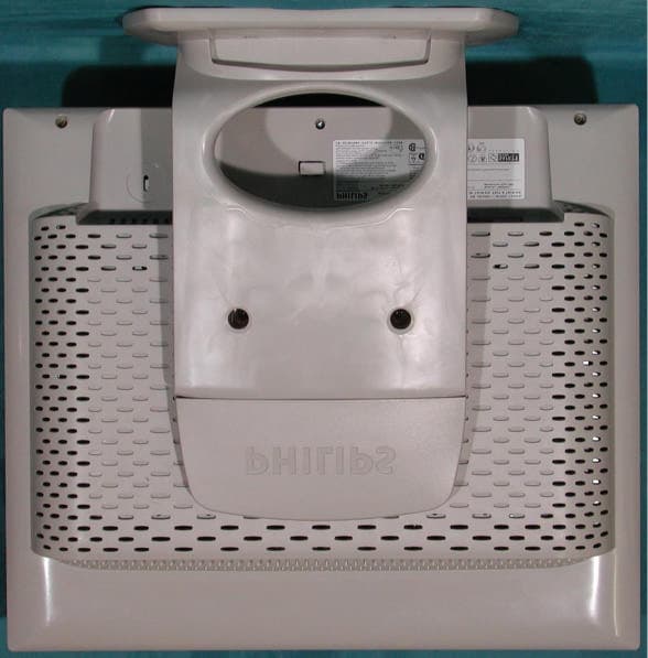
Click to zoom
Application Details
- Equipment Class
- JBP - Part 15 Class B Computing Device Peripheral
- Date of Grant
- Sep 03, 2001
- Application Purpose
- Original Equipment
- Date of Application
- Sep 02, 2001
- Equipment Note
- 17" Color LCD Monitor
- Country
- Taiwan
Documents & Files
Document Text
Text extracted from the exhibit documents filed with the FCC. Open a document above to read the original.
Users Manual
FCC ID: A3KM104 Exhibit-3 FCC ID: A3KM104 FCC ID: A3KM104
Block Diagram
FCC ID: A3KM104 Exhibit-5
Cover Letter(s)
Safety & Compliance Consulting 29 Sweetman Lane West Milford, NJ 07480-2932 Tel/Fax (973) 728-5141 September 3, 2001 PHI2001-F010 TCB Form 731 Confirmation No: TC102243 Federal Communications Commission Equipment Approval Services 7435 Oakland Mills Road Columbia, MD. 21046 Subject:Original TCB Certification Application for Class B Computing Device Peripheral FCC ID: A3KM104 / Philips 17” Color LCD Monitor, Model 170B2 Series Gentlemen: Enclosed, please find Philips Electronics Industries (Taiwan) Ltd.’s original application for equipment authorization dated August 27, 2001. The subject device is in compliance with Part 15, Subpart B of the FCC Rules. This is to report 17" Color Flat Panel LCD Monitor provided with such features as: (1) supports 30-82 kHz horizontal, 56-75 Hz vertical sync frequencies and maximum resolution up to 1280x1024, Non- Interlaced; (2) detachable non-shielded power supply cord; (3) detachable shielded 15-Pin D-Sub (analog) and DVI (digital) video signal cables each with two external ferrite cores. This monitor may be provided with an optional USB powered hub base unit, but it is not yet available and is not part of this filing. The subject-monitor was system tested in accordance with C63.4-1992 to show compliance with FCC Part 15 Class B limits. Compliance tests were performed in representative worst-case video modes: (1) 1024x1024 @ 80 kHz (D-Sub to D-Sub); (2) 1280x1024 @ 80 kHz ((DVI to DVI); and (3) 1024x768 @ 60 kHz (D-Sub to DVI). Should you have any questions or comments, please contact the undersigned who is an authorized agent for the subject application. Thank you for your attention and cooperation in this matter. Sincerely yours, Richard Mullen Group Manager Safety & Compliance Consulting [email protected] Cc: Randy Ortanez / PCTEST Engineering Laboratory, Inc.
External Photos
FCC ID: A3KM104 Exhibit 7 Photographs of EUT and Test Configuration Front View FCC ID: A3KM104 Rear View
ID Label/Location Info
FCC ID: A3KM104 Exhibit-2
ID Label/Location Info
FCC ID: A3KM104 FCC ID Label
Internal Photos
FCC ID: A3KM104 Front Cabinet FCC ID: A3KM104 Panel Assembly FCC ID: A3KM104 Shielding Cover FCC ID: A3KM104 Panel Assembly w/o Shielding Cover FCC ID: A3KM104 Panel Assembly with Shielding Plate FCC ID: A3KM104 Shielding Plate FCC ID: A3KM104 LCD Panel FCC ID: A3KM104 PCB Layout FCC ID: A3KM104 PCB Layout FCC ID: A3KM104 Power Cord and I/F Cable
Operational Description
FCC ID: A3KM104 Exhibit-4 Function Description 1. General The 17“ TFT flat panel monitor is specified as a display peripheral with analog video signal and Intel digital inputs and 17” TFT LCD display. Horizontal scan range is 31 - 82 K Hz and the refresh range is 56 - 75 Hz. This scan range allows it to display resolution up to 1280*1024 non- interlaces at 75 Hz refresh rate. The image can be adjusted through OSD control. These adjustments can be stored in an onboard memory including 32 factory pre-set modes and 7 user definable modes. 2. Power supply Main voltage : AC 90 - 264 V rms, 50 - 60 Hz power consumption : 42 W Max power indicator : LED ( on: green, standby: amber, new mode: blinking green) Auto power Saving : EPA, Nutek, VESA DPMS 3. Input signal Horizontal scan : 31 - 82 K Hz Vertical scan : 56 - 75 Hz Input signals 1. Signal input level Video : 0.7 Vp-p linear / 75 ohms Sync : H/H+V, V TTL level, composite sync, sync on green 2. Impedance Video : Terminated with 75 ohms Sync : Terminated with 2K2 ohms 3. Intel DVI Digital Single channel TMDS signal 4. OSD ( On Screen Display ) function Software control function via OSD/ Control -Adjustable functions : MAIN CONTROLS LANGUAGE ADJUST POSITION ADJUST SIZE BRIGHTNESS & CONTRAST VIDEO NOISE ADJUST COLOR OSD SETTINGS PRODUCT INFORMATION RESET TO FACTORY SETTINGS FCC ID: A3KM104 INPUT SELECTION CLOSE MAIN CONTROLS MOVE SELECTION THEN ok LANGUAGE : ENGLISH , ESPANOL , FRANCAIS , DEUTSCH , ITALIANO, JAPANESE ADJUST POSITION : HORIZONTAL VERTICAL ADJUST SIZE : full screen, native mode, user settings. BRIGHTNESS & CONTRAST : brightness and contrast adjustment. VIDEO NOISE : Phase adjustment, Clock adjustment, Image optimization ADJUST COLOR : original panel color , 9300K for general use , 6500k for image management, user red green blue adjust. OSD POSITION : OSD H-position, OSD V-position PRODUCT INFORMATION : show product information RESET TO FACTORY SETTING: recall to Factory preset settings. INPUT SELECTION : analog(D-sub), digital(DVI), analog(DVI) 5. LCD panel Type : 17” LCD flat panel Dimensions : 17“ (43.2cm) Pitch : 0.264 mm Color pixel arrangement : R.G.B. vertical stripes Display surface : low reflection, antiglare with hard coating Number of color : 256 gray level ( 8 bits ) Backlight : CCFL edge light system Active area ( W*H) : 337*270 mm ( 17“ diagonal ) 6. Function block Video Switch - switch two analog input signals from D-sub or DVI-A. Scaler (GM5020) a.) ADC - brightness control - contrast control - R.G.B. sub contrast control - sample the input video signal according to its pixel rate to form a digital data for format converter b.) TMDS - decode 4 pairs of TMDS signals to get 8 bits R,G, B data and sync signals c.) Format converter - convert the data from ADC to a LCD panel acceptable data format FCC ID: A3KM104 - zoom the input video to a full screen display LVDS - convert R, G, B data and sync data from scaler IC to panel Microprocessor - monitor the input horizontal and vertical sync signal to judge input video mode - send the parameters to format converter IC according to the input mode - process the control data listed in OSD section Front panel switch control - used by OSD function - six push button (OSD confirm, up/down(brightness), right/left, auto) Inverter - accept +12 V DC voltage - output 800 Vrms AC voltage to CCFL ( Cold Cathode Fluorescent Tube, backlight ) Power supply - AC adapter : the AC power input from 90 V AC to 264 V AC, can generate 12V / 5A AC power - DC DC converter : convert 12 V to 5 V , 3.3 V to system USB function - device function: one up stream port - hub function : one upstream port, four down stream ports.
Test Report
FCC ID: A3KM104 Exhibit 6 Statement of Data Measured and Test Data 1. General Information of EUT The EUT, 17” LCD color monitor : Model No. : 170B2 FCC ID : A3KM104 Brand : Philips The color monitor automatically scans horizontal frequencies between 30HKz and 82KHz , and vertical frequencies between 50Hz and 75Hz. This color monitor displays sharp and brilliant images of text and graphics with a maximum resolution up to 1280x1024 pixels. The monitor has 15 factory-preset modes as indicated in the following table: 2.Test Equipment and Procedure Test was performed by: PHILIPS ELECTRONICS INDUSTRIES (TAIWAN) LTD. CONSUMER ELECTRONICS DIVISION EMI – LAB 5, Tze Chiang 1 Road, Chungli Industrial Park P.O. Box 123, Chungli, Taoyuan, Taiwan R. O. C. Tel : 886-3-4549862 Fax : 886-3-4549887 Internet: [email protected] Resolution H-Frequency V-Frequency Remark M01 640 X 350 31.5KHz 70Hz Non-interlaced M02 720 X 400 31.5KHZ 70Hz Non-interlaced M03 640 X 480 31.5KHZ 60Hz Non-interlaced M04 640 X 480 35.0KHz 67Hz Non-interlaced M05 640 X 480 37.5KHz 75Hz Non-interlaced M06 800 X 600 35.1KHz 56Hz Non-interlaced M07 800 X 600 37.9KHz 60Hz Non-interlaced M08 800 X 600 46.9KHz 75Hz Non-interlaced M09 832 X 624 49.7KHz 75Hz Non-interlaced M10 1024 X 768 48.4KHz 60Hz Non-interlaced M11 1024 X 768 60.0KHz 75Hz Non-interlaced M12 1152 X 870 69.0KHz 75Hz Non-interlaced M13 1152 X 900 71.8KHz 76Hz Non-interlaced M14 1280 X 1024 63.9KHz 60Hz Non-interlaced M15 1280 X 1024 80.0KHz 75Hz Non-interlaced FCC ID: A3KM104 The test was performed in accordance with ANSI C63.4-1992, “AMERICAN NATIONAL STANDARD FOR MEASUREMENT OF RADIO-NOISE EMISSION FROM LOW- VOLTAGE ELECTRICAL AND ELECTRONIC EQUIPMENT IN THE RANGE OF 9KHz TO 40GHz” Test equipment used for line Conducted and Radiated emissions as following. All equipment were calibrated according to ANSI C63.4-1992 and ISO-9000 requirement unless otherwise specified. Test Equipment Model No. Serial No. Next Calibrate Spectrum HP8568B 2415A00346 5/26/2002 RF Preselector HP85685A 2901A00946 5/26/2002 QP Adapter HP85650A 2043A00366 5/26/2002 EMI Receiver HP85460A 3441A00199 9/05/2001 RFI Filter Section HP85460A 3330A00177 9/05/2001 EMI Receiver R & S ESVS30 841977/006 12/19/2001 Biconical Antenna EMCO 3110B 3222 4/23/2002 Biconical Antenna EMCO 3110B 3224 4/23/2002 Log-Periodic Antenna EMCO 3146A 1424 4/23/2002 Log-Periodic Antenna EMCO 3146A 1425 4/23/2002 LISN EMCO 3825/2 9311-2153 11/27/2001 LISN EMCO 3825/2 9311-2154 11/27/2001 LISN R & S ESH3-Z5 8315518542 12/07/2001 Turn Table EMCO 1060 1068 11/23/2001 Antenna Tower EMCO 1050 1113 11/23/2001 RF Cable M17/75-RG214-NE N/A 11/23/2001 Computer HP9000/300 2614A78610 N/A Printer HP2225A 2728S02586 N/A Plotter HP7440A 2539A40856 N/A Traceability to R.O.C. and international standards is assured by using calibrated all equipment. For system measurement, the EUT “170B2” were connected to: The system was configured for testing in a typical fashion ( as a customer would normally use it ) according to ANSI C63.4-1992, please see the photographs for detail. Item Model No. Serial No. FCC ID 1. Computer Compaq ENC-P733 6040DYSZE404 FCC Logo 2. Keyboard Compaq KB-9963 B26950GGALP13Q FCC Logo 3. Mouse Logitech M-S48A F2240H5BLN0AQ JNZ201213 4. Printer HP 2225C 3123S97227 DSI6XU2225 5. Modem USRobotics 268 0002680559278575 CJE-0318 6. Vide Card ATI RADEON AGP N/a FCC Logo FCC ID: A3KM104 Both conducted and radiated testing were performed according to the procedure in ANSI C63.4-1992. Conducted testing was performed in screen room and radiated testing was performed in open site at an antenna to EUT distance of 3-meter on horizontal and vertical polarization. First, pre-scan all modes in screen room then select 3 higher modes (worst case) were tested and reported. The line conductive interference was tested with 110VAC and 220VAC receptively. Unshielded power cord was used during test. Tested and reported modes as following: Report No. Resolution Frequencies I/F Cable EMI01-030 1280x1024 80.0KHz/75Hz D-Sub - D-Sub EMI01-030A 1280x1024 80.0KHz/75Hz DVI - DVI EMI01-030B 1024x768 60.0KHz/75Hz D-sub - DVI 3. Test Program and Test Results Set up the EUT and all peripherals as chapter 6 of ANSI C63.4-1992 for AC power line conducted emissions testing and radiated emissions testing. Turn on the power of EUT and all peripherals, select an appropriate displaying mode using the “setup” software. Then run an EMI test program “HTEST.EMI” as a basic software to execute the EUT operating under test. Step 1 : Run the “HTEST.EMI” on personal computer then sends “H” character to monitor continuously until full screen. Step 2 : Personal computer sends a complete line of continuously repeating “H” to HP 2225C printer. Step 3 : Personal computer sends a file of “H” pattern to floppy disk then read a file of “H” pattern from floppy disk. Step 4 : Personal computer sends a file of “H” pattern to hard disk then read a file of “H” pattern from hard disk. Step 5 : Personal computer sends a file of “H” patter to USRobotics 268 modem. Step 6 : Return to step 1 All data in this report are “PEAK” value within 15dB margin unless otherwise noted. The radiated (open site) data has included antenna and cable factors, sample calculation: Final Value (dBμv/m) = Reading (dBuv) + Antenna Factor (dB) + Cable Loss (dB) The measured data of radiated RF interference at open site and line conducted interference as attached. FCC ID: A3KM104
Test Report
FCC ID: A3KM104 FCC TEST REPORT Report No. : EMI01-030 Tested Date: Aug./13/2001 Test Performed By Philips Electronics Industries (Taiwan) Ltd. Business Electronics EMC Lab. No. 5, Tze Chiang 1 Road, Chungli, Taoyuan, Taiwan, R.O.C. Tel.: + 886-3-454-9862 Fax.: +886-3-454-9887 Manufacturer : Philips Business Electronics Tested System: 1. EUT : Philips 170B2 LCD color monitor s/n: TY0104030 FCC ID : A3KM104 2. Computer : Compaq ENC-P733 s/n: 6040DYSZE404 FCC ID : FCC Logo 3. Keyboard : Compaq KB-9963 s/n: B26950GGALP13Q FCC ID : FCC Logo 4. Mouse : M-S48A s/n: F2240H5BLN0AQ FCC ID : JNZ201213 5. Modem : USRoboties 268 s/n: 002680559278575 FCC ID : CJE-0318 6. Printer : HP2225C s/n: 3123S97227 FCC ID : DSI6XU2225 7. Video Card : ATI RADEON AGP s/n: n/a FCC ID : FCC Logo Note: Test was performed in according with FCC measurement procedure ANSI C63.4-1992 “AMERICAN NATIONAL STANDARD FOR MEASUREMENT OF RADIO-NOISE EMISSION FROM LOW-VOLTAGE ELECTRONIC EQUIPMENT IN THE RANGE OF 9KHz TO 40GHz” Monitor was connected to floor mounted AC outlet. 80.0KHz mode (1280x1024/75Hz) was tested. D-sub to D-sub I/F cable with two ferrite cores was used. Non-shield power cord was used during test. The test equipment used for testing please refer to the list as attached. Deviation: None Radiated RF Level – Peak Value Frequency Horizontal Vertical FCC/B Limit (MHz) (dBuv/m) (dBuv/m) (dBuv/m) 67.79 23.94 31.44 40.0 128.18 34.34 35.24 43.5 135.23 28.95 32.65 43.5 169.03 35.17 37.47 43.5 192.26 32.72 30.12 43.5 224.31 32.58 33.78 46.0 236.65 39.25 36.15 46.0 256.36 37.9 36.6 46.0 269.03 39.46 41.76 46.0 320.45 36.08 36.98 46.0 FCC ID: A3KM104 352.5 36.4 35.3 46.0 368.52 31.7 33.9 46.0 384.54 35.46 38.76 46.0 416.58 33.2 36.9 46.0 480.66 34.89 36.99 46.0 512.7 34.7 39.3 46.0 544.76 37.68 36.68 46.0 576.82 36.62 36.72 46.0 608.86 37.78 38.18 46.0 640.9 36.64 38.04 46.0 737.02 38.65 39.25 46.0 769.08 39.5 39.81 46.0 961.35 43.87 43.77 54.0 Spectrum Analyzer Setting: RBW: 100KHz VBW: 100KHz Quasi-peak Values were taken with Rohde & Schwarz ESVS 30 EMI test receiver. Radiated RF Level – QP Value Frequency Horizontal Vertical FCC/B Limit (MHz) (dBuv/m) (dBuv/m) (dBuv/m) 288.41 38.9 38.3 46.0 448.64 36.27 42.47 46.0 672.94 35.66 36.86 46.0 801.12 37.51 40.11 46.0 833.17 39.82 40.02 46.0 897.26 38.88 41.78 46.0 The spectrum was scanned from 30MHz to 1000MHz and the significant emissions were recorded. Test distance between device under test and receiving antenna was 3-meter. Sample of calculation: Final value (dBuv/m) = Antenna Factor (dB) + Cable Loss (dB) + Reading value (dBuv/m) Tested by: C.C.Wu Checked by: K.J.Hsu EMI Technician MC Engineer NVLAP Signatory FCC ID: A3KM104 FCC ID: A3KM104 FCC ID: A3KM104 FCC ID: A3KM104 FCC TEST REPORT Report No. : EMI01-030A Tested Date: Aug./15/2001 Test Performed By Philips Electronics Industries (Taiwan) Ltd. Business Electronics EMC Lab. No. 5, Tze Chiang 1 Road, Chungli, Taoyuan, Taiwan, R.O.C. Tel.: + 886-3-454-9862 Fax.: +886-3-454-9887 Manufacturer : Philips Business Electronics Tested System: 1. EUT : Philips 170B2 LCD color monitor s/n: TY0104030 FCC ID : A3KM104 2. Computer : Compaq ENC-P733 s/n: 6040DYSZE404 FCC ID : FCC Logo 3. Keyboard : Compaq KB-9963 s/n: B26950GGALP13Q FCC ID : FCC Logo 4. Mouse : M-S48A s/n: F2240H5BLN0AQ FCC ID : JNZ201213 5. Modem : USRoboties 268 s/n: 002680559278575 FCC ID : CJE-0318 6. Printer : HP2225C s/n: 3123S97227 FCC ID : DSI6XU2225 7. Video Card : ATI RADEON AGP s/n: n/a FCC ID : FCC Logo Note: Test was performed in according with FCC measurement procedure ANSI C63.4-1992 “AMERICAN NATIONAL STANDARD FOR MEASUREMENT OF RADIO-NOISE EMISSION FROM LOW-VOLTAGE ELECTRONIC EQUIPMENT IN THE RANGE OF 9KHz TO 40GHz” Monitor was connected to floor mounted AC outlet. 80.0KHz mode (1280x1024/75Hz) was tested. DVI to DVI I/F cable with two ferrite cores was used. Non-shield power cord was used during test. The test equipment used for testing please refer to the list as attached. Deviation: None Radiated RF Level – Peak Value Frequency Horizontal Vertical FCC/B Limit (MHz) (dBuv/m) (dBuv/m) (dBuv/m) 67.62 28.54 27.65 40.0 68.37 23.34 33.84 40.0 135.23 30.35 32.45 43.5 160.23 34.2 33.7 43.5 192.27 33.02 29.72 43.5 256.35 39.6 37.3 46.0 320.45 37.88 35.88 46.0 336.48 35.86 34.16 46.0 384.54 36.96 38.75 46.0 405.69 36.27 36.17 46.0 464.62 39.36 36.46 46.0 FCC ID: A3KM104 480.66 36.29 39.19 46.0 515.46 36.92 37.82 46.0 576.8 36.72 37.62 46.0 640.9 37.54 38.94 46.0 644.33 38.26 39.66 46.0 672.96 41.66 42.86 46.0 961.35 44.76 44.27 54.0 980.34 45.7 45.5 54.0 Spectrum Analyzer Setting: RBW: 100KHz VBW: 100KHz Quasi-peak Values were taken with Rohde & Schwarz ESVS 30 EMI test receiver. Radiated RF Level – QP Value Frequency Horizontal Vertical FCC/B Limit (MHz) (dBuv/m) (dBuv/m) (dBuv/m) 128.19 36.54 36.94 43.5 288.41 43.3 42.8 46.0 352.49 40.0 36.5 46.0 448.64 37.37 40.57 46.0 544.76 38.38 38.78 46.0 608.86 40.58 42.28 46.0 676.16 41.92 41.02 46.0 705.0 38.28 37.08 46.0 737.04 36.45 38.85 46.0 753.0 39.14 42.24 46.0 769.08 36.1 38.4 46.0 801.13 40.31 40.71 46.0 833.17 36.52 39.12 46.0 845.15 39.92 38.92 46.0 865.23 38.66 40.06 46.0 897.27 39.18 42.48 46.0 902.06 37.3 40.2 46.0 929.31 38.74 41.04 46.0 The spectrum was scanned from 30MHz to 1000MHz and the significant emissions were recorded. Test distance between device under test and receiving antenna was 3-meter. Sample of calculation: Final value (dBuv/m) = Antenna Factor (dB) + Cable Loss (dB) + Reading value (dBuv/m) Tested by: C.C.Wu Checked by: K.J.Hsu EMI Technician MC Engineer NVLAP Signatory FCC ID: A3KM104 FCC ID: A3KM104 FCC ID: A3KM104 FCC ID: A3KM104 FCC TEST REPORT Report No. : EMI01-030B Tested Date: Aug./18/2001 Test Performed By Philips Electronics Industries (Taiwan) Ltd. Business Electronics EMC Lab. No. 5, Tze Chiang 1 Road, Chungli, Taoyuan, Taiwan, R.O.C. Tel.: + 886-3-454-9862 Fax.: +886-3-454-9887 Manufacturer : Philips Business Electronics Tested System: 1. EUT : Philips 170B2 LCD col…
Text truncated - open the document above for the full version.
Test Setup Photos
FCC ID: A3KM104 Conducted Emissions Test FCC ID: A3KM104 Conducted Emissions Test FCC ID: A3KM104 Radiated Emissions Test FCC ID: A3KM104 Radiated Emissions Test
Contact Information
Applicant
Ronnie Yang(Manager, Safety/DEV)
Technical Contact
Safety & Compliance ConsultingRichard Mullen
[email protected](973) 728-5141
29 Sweetman Lane · West Milford, New Jersey · United States
Test Firm
Philips Electronics Industries (Taiwan) Ltd.Ronnie Yang
Technical Specifications
| # | Rule Parts | Frequency Range | Power Output |
|---|---|---|---|
| 1 | 15B | - | - |
Other Applications from Philips Electronics Industries (Taiwan) Ltd
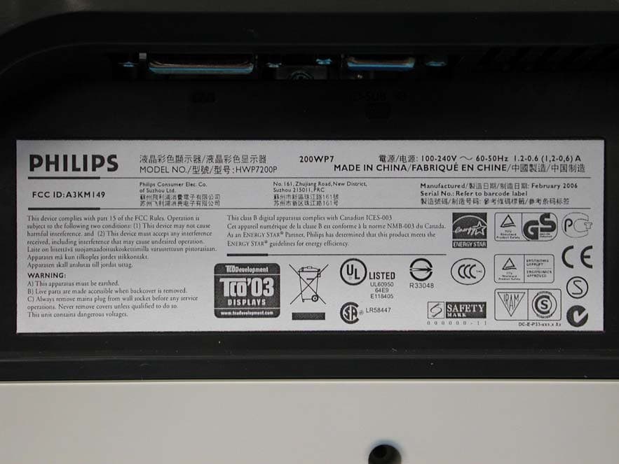
A3KM149
Mar 16, 200620� LCD Monitor
Equipment Class
JBP - Part 15 Class B Computing Device Peripheral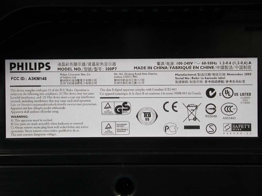
A3KM148
Dec 15, 200520
Equipment Class
JBP - Part 15 Class B Computing Device Peripheral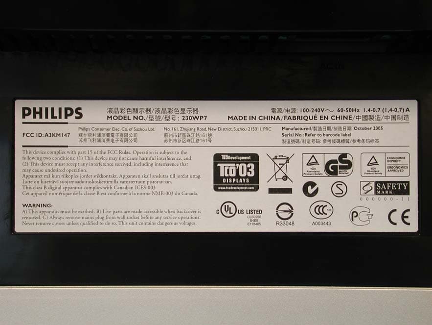
A3KM147
Nov 17, 2005LCD Monitor
Equipment Class
JBP - Part 15 Class B Computing Device Peripheral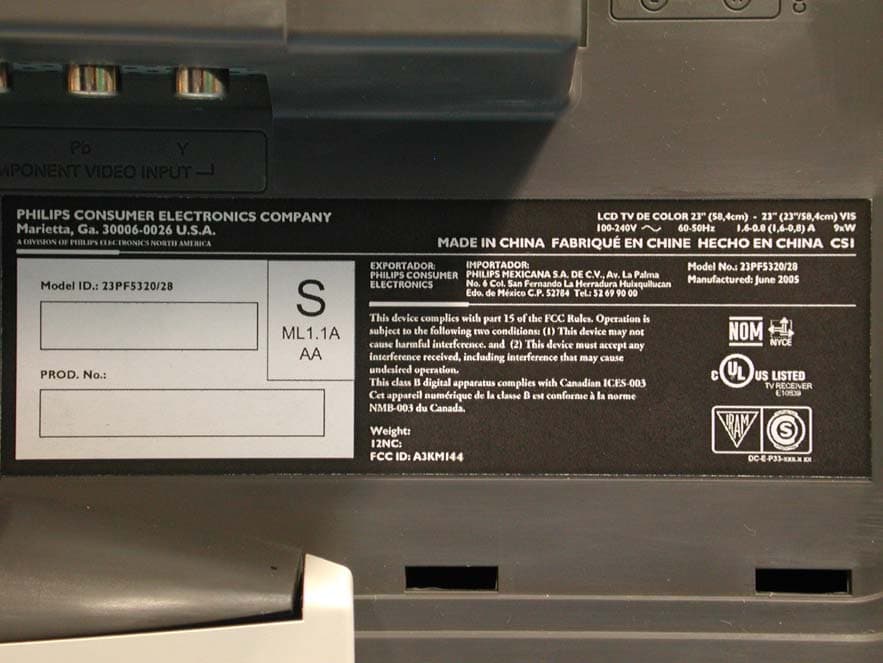
A3KM144
Jul 19, 2005LCD TV
Equipment Class
JBP - Part 15 Class B Computing Device Peripheral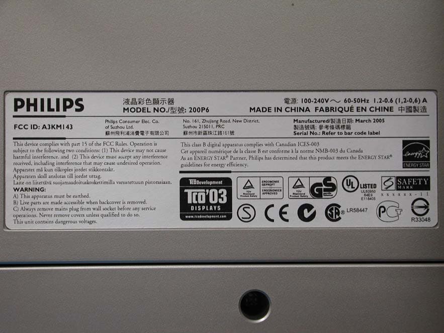
A3KM143
Apr 18, 2005Display Color Monitor
Equipment Class
JBP - Part 15 Class B Computing Device Peripheral