A3KM116LCD Monitor
Philips Electronics Industries (Taiwan) Ltd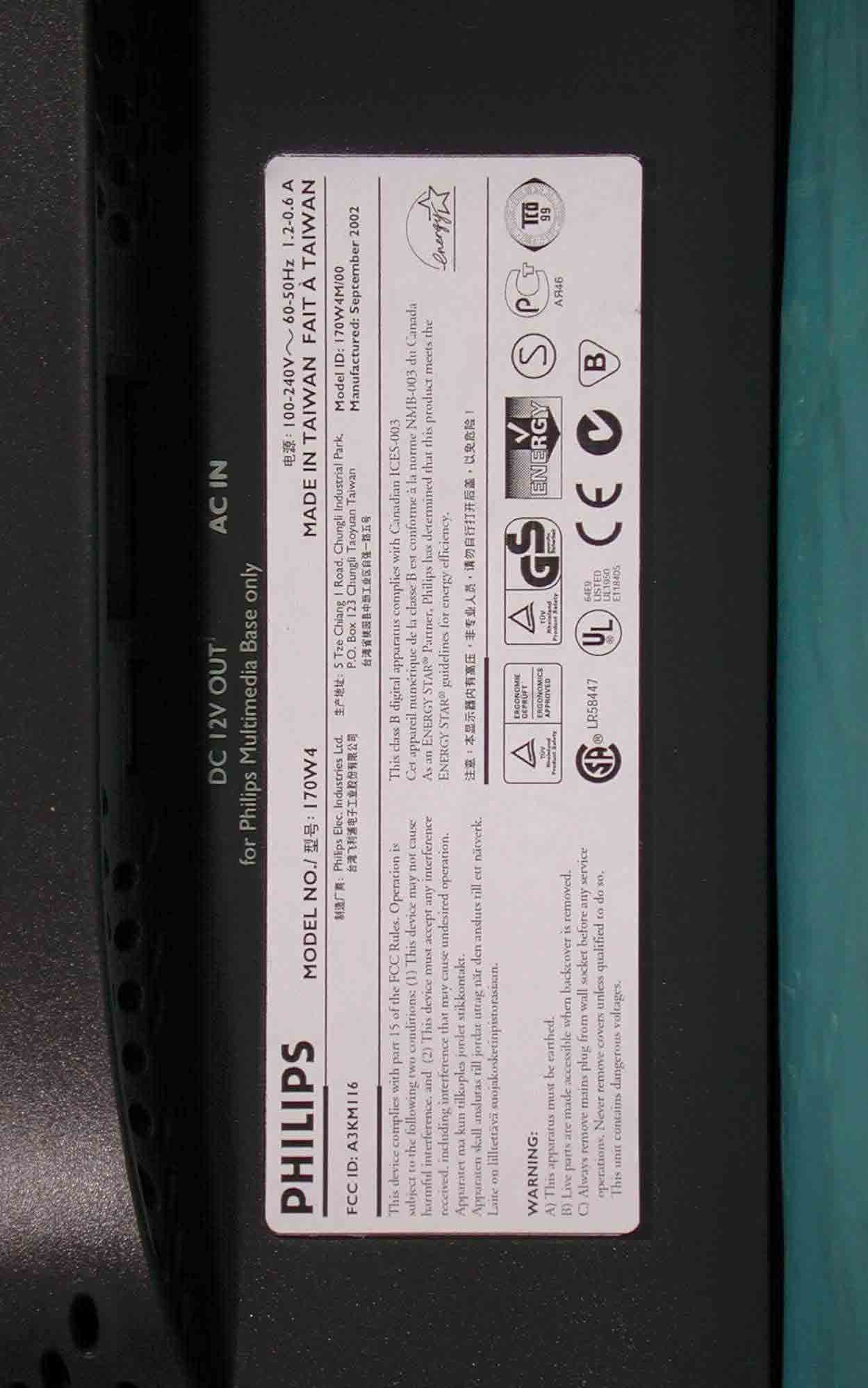
Click to zoom
Application Details
- Equipment Class
- JBP - Part 15 Class B Computing Device Peripheral
- Date of Grant
- Nov 06, 2002
- Application Purpose
- Original Equipment
- Date of Application
- Nov 06, 2002
- Equipment Note
- LCD Monitor
- Country
- Taiwan
Documents & Files
Document Text
Text extracted from the exhibit documents filed with the FCC. Open a document above to read the original.
Users Manual
Product Information Product Features • Technical Specifications • Resolution & Preset Modes • Philips Pixel Defect Policy • Automatic Power Saving • Physical Specification • Pin Assignment • Product Views • Physical Function Product Features 170W4P z 17-inch color LCD monitor with excellent Wide-Screen display performance z Dual input - accepts DVI-D digital and VGA analog inputs z Embedded AC power supply z Advanced AUTO adjustment optimizes picture quality. z Adjustable tilt and swivel function z Rotation for both portrait and landscape display RETURN TO TOP OF THE PAGE Technical Specifications* LCD PANEL • TypeTFT LCD • Screen size17.1" / 43.4cm visual • Pixel Pitch0.291 x 0.291mm • LCD Panel type 1280 x 768 pixels R.G.B. vertical stripe Anti-glare polarizer hardness • Effective viewing area372.48 x 223.49 mm • Display Colors8 bits (16M colors) SCANNING Vertical refresh rate56Hz-70Hz Horizontal Frequency30kHz-61kHz VIDEO • Video dot rate75MHz • Input impedance - Video 75 ohm - Sync 2K ohm • Input signal levels0.7 Vpp • Sync input signal Separate sync Composite sync Sync on green Exhibit 3 Installstion and Operating instructions * This data is subject to change without notice. RETURN TO TOP OF THE PAGE Resolution & Preset Modes • Sync polaritiesPositive and negative • Video interface Dual input (two connectors): D-Sub (analog) and DVI-D (digital) are available and user selectable Optical characteristics • Contrast ratio: 350 (typ.) • Brightness: 450 cd/m 2 (typ.) • Peak contrast angle:6 o'colock • White Chromatcity: x: 0.283 y: 0.297 (at 9300°K) x: 0.313 y: 0.329 (at 6500°K) • Viewing Angle: (C/R>5) Upper >50° (typ.) Lower > 70° (typ.) Left > 75° (typ.) Right > 75° (typ.) • Viewing Angle: (C/R>10) Upper >45° (typ.) Lower >45° (typ.) Left >60° (typ.) Right >60° (typ.) • Response time <25ms (typ.) • Maximum1280 x 768 at 70Hz • Recommended 1280 x 768 at 60Hz 28 user definable modes 15 factory preset modes: 31.5 640*350 70 31.5 720*400 70 31.5 640*480 60 35.0 640*480 67 37.5 640*480 75 35.2 800*600 56 37.9 800*600 60 46.9 800*600 75 49.7 832*624 75 48.4 1024*768 60 60.0 1024*768 75 RETURN TO TOP OF THE PAGE Automatic Power Saving If you have VESA DPMS compliance display card or software installed in your PC, the monitor can automatically reduce its power consumption when not in use. If an input from a keyboard, mouse or other input device is detected, the monitor will 'wake up' automatically. The following table shows the power consumption and signaling of this automatic power saving feature: RETURN TO TOP OF THE PAGE Physical Specifications 44.4 1280*768 56 47.7 1280*768 60 56.0 1280*768 70 52.5 1280*720 70 Power Management Definition VESA Mode Video H-sync V-sync Power Used LED color ON Active Yes Yes < 40 W Green Stand-by Blanked No Yes < 1W Amber Suspend Blanked Yes No < 1W Amber OFF Blanked No No < 1W Amber This monitor is E NERGY S TAR ® compliant. A s an E NERGY S TAR ® P artner, PHILIPS has determined that this product meets the ENERGY STAR ® guidelines for energy efficiency. • Dimension (WxHxD) 417 x 374 x 180 mm (incl. Pedestal) • Weight 6 kg • Tilt / Swivel- 5° ~ 35° / + - 175° • Power supply100 — 240 VAC, 50/60 Hz • Power consumption 35 W (typ.) • Temperature 5° C to 35° C (operating) -20° C to 60° C (storage) • Relative humidity 20% to 80% • System MTBF50K hrs (including CCFL 50K hrs) * This data is subject to change without notice. RETURN TO TOP OF THE PAGE Pin Assignment 1. The digital only connector contains 24 signal contacts organized in three rows of eight contacts. Signal pin assignments are listed in the following table: 2. The 15-pin D-sub connector (male) of the signal cable: Pin No. Signal Assignment Pin No. Signal Assignment Pin No. Signal Assignment 1 T.M.D.S. Data2- 9 T.M.D.S. Data1-17T.M.D.S. Data0- 2 T.M.D.S. Data2+ 10 T.M.D.S. Data1+18T.M.D.S. Data0+ 3 T.M.D.S. Data2/4 Shield 11 T.M.D.S. Data1/3 Shield 19 T.M.D.S. Data0/5 Shield 4 No connect 12 No connect 20No connect 5 No connect 13 No connect 21No connect 6 DDC Clock 14 +5V Power 22 T.M.D.S. Clock Shield 7 DDC Data 15 Ground (for +5V)23T.M.D.S. Clock+ 8 No connect 16 Hot Plug Detect24T.M.D.S. Clock- Pin No. Assignment Pin No. Assignment 1 Red video input 9 DDC +5V 2 Green video input 10 Logic ground 3 Blue video input 11 Identical output - connected to pin 10 RETURN TO TOP OF THE PAGE Product Views Follow the links to see various views of the monitor and its components. Front View Product Description RETURN TO TOP OF THE PAGE Physical Function 4 Identical output - connected to pin 10 12 Serial data line (SDA) 5 Cable detect 13 H. Sync / H+V 6 Red video ground 14 V. Sync 7 Green video ground 15 Data clock line (SCL) 8 Blue video ground 1) Tilt 2) Swivel Installing your LCD Monitor Your LCD Monitor : Front View Product Description • Connecting to Your PC • Remove and re-install the base • Getting Started • Optimizing Performance Front View Product Description RETURN TO TOP OF THE PAGE UP and DOWN buttons are used when adjusting the OSD of your monitor LEFT and RIGHT buttons, like the UP and DOWN buttons, are also used in adjusting the OSD of your monitor. BRIGHTNESS hotkey. When the UP and DOWN arrow buttons are pressed, the adjustment controls for the BRIGHTNESS will show up. OK button which when pressed will take you to the OSD controls POWER button switches your monitor on Automatically adjust the horizontal position, vertical position, phase and clock setting. Signal inputs selective hotkeys. Allows user to switch between two video connectors (D-Sub & DVI-D), e.g. D-Sub <-> DVI-D digital inputs. Optimizing Performance z For best performance, ensure that your display settings are set at 1280x768@60Hz. z You can also install the Flat Panel Adjust (FP Adjust) program, a program for getting the best performance out of your monitor. This included on this CD. Step-by-step instructions are provided to guide you through the installtion process. Click on the link to know more about this program. More about FP_setup…
Text truncated - open the document above for the full version.
Block Diagram
Exhibit 4 Brief Description of Circuit Functions Function Description for Hudson3-170W4P 1. General The 17” Wide XGA TFT LCD monitor is specified as a display peripheral with analog ,digital(DVI). Horizontal scan range is 30KHz-64KHz and the refresh range is 56Hz-75Hz in normal mode. This scan range allows it to display resolution up to 1280x768@75Hz non-interlace input. The image can be adjusted by OSD control. These adjustments can be stored in an onboard memory. 2. Power supply Main voltage : AC 90-264Vrms, 50-60Hz Power consumption : 45W Max. Power indicator : LED(ON: green, standby: amber) Auto power saving : VESA DPMS 3. Input signal Horizontal scan : 30-64KHz Vertical scan : 56-75Hz(from VGA to XGA for analog/digital), 60-75Hz(for wide XGA analog/digital), Input signals : A. D-sub /DVI-analog signal input level Video : 0.7Vp-p linear/75 ohms Sync : H/H+V,V TTL level,composite sync, sync on green B. Analog signal impedance Video : Terminated with 75 ohms Sync : Terminated with 2K2 ohms C. Intel DVI- digital Single channel TMDS signal 4. OSD( On Screen Display) function Software control function via OSD -Main controls: Language----------------- 6 Languages Adjust position-----------Horizontal,Vertical Adjust Size--------------- Full screen,Native mode,Fill with aspect Brightness & Contrast-- Brightness, Contrast Video Noise-------------- Phase, Clock Adjust color-------------- Original panel color, 9300K, 6500K, User preset OSD Settings------------- Horizontal,Vertical Product information----- Serial No, Resolution, Signal input Input selection------------Analog(D-SUB), Digital(DVI), Reset to factory setting-- No/Yes Exit Main controls 5. LCD Panel Type : 17” Wide LCD flat panel Dimensions : 17”(417 x 374 x 18 mm) Pitch : 0.291mmx0.291mm Color pixel arrangement : RGB vertical stripes Number of color : 64 gray level (6 bits) Backlight : 4 CCFL’s Active area (W*H) : 372.5 x 223.5mm 6. Function block Scaler GM5020 (contains following functions ) : (1) ADC - Included video switch, support 2-channel RGB input. - Sample the input video signal according to its pixel rate to form a digital data for format converter IC. (2) TMDSRx - Convert serial digital signal to parallel digital RGB signal, it can reduce EMI. (3) Format converter - Built in GPIO port, mode detection. - Convert the image data from ADC, TMDSRx or Video Decoder to LCD panel data format. - Zoom the input video to full screen display. LVDSTx - Convert digital image signal to serial LVDS signal. Inverter - Accept +12VDC voltage. - Provide 720Vrms voltage for CCFL. Power supply - AC adapter : AC power input (from 90VAC to 264VAC) can generate +12VDC, and +5VDC power - DC to DC converter : Convert +12V to +3.3VDC power. DC-AC Inverter AC Adapter DC-DC Converter Exhibit 5 Block Diagram HUDSON 170W4 ARCHITECTURE AND INTERCONNECTION Scalar PCB Format Conversion & DC-DC LVDS Adapter LCD PANEL Front Control Panel Audio Module or USB Hub Repeater (Optional function) AC Mains DVI-D D-SUB AC ADPTER (+12V) CIRCUIT ARCHITECTURE OF SXGA LCD MONITOR GM5020 DVI-D DDC2B R/A R/D D-sub Analog ( R , G ,B) G/A G/D H/V(TMDS ) (G) H/V B/A B/D Analog / Digital select H H/V CLK HSYNC SI_DE RAS/CAS/WE HS_ADC (OPTION) I 2 C (SDA ,SCL) DDC2B AC 90 ∼ 260V PLL Clock Generator EEPROM 24C16 Front panel Control ADC TFT LCD MODULE BACK LIGHT DC-AC INVERTER DC-DC Converter (+12V, +5V, +3.3V) USB Hub Repeater Audio Amplifier R (A 0~7 ,B 0~7 ) G (A 0~7 ,B 0~7 ) B (A 0~7 ,B 0~7 ) Format conversion MCU MC68HC908 LD64 ADC Block ADC ADC Frame Buffer (1Mx16 SDRAM ) x3 Sync pre- p rocessor OSD TMDS receiver SiI161A DDC Sync Slicer ( Discrete ) 24C02 24C02 LVDS
External Photos
FCC ID: A3KM116 Exhibit 7 Photographs Front View FCC ID: A3KM116 Rear View FCC ID: A3KM116 Label FCC ID: A3KM116 Assembly w/o Base
ID Label/Location Info
Exhibit 2 FCC ID Label
Internal Photos
FCC ID: A3KM116 Assembly w/o Back Cover FCC ID: A3KM116 Shielding Cover FCC ID: A3KM116 Assembly w/o Shielding Cover FCC ID: A3KM116 PCB Layout FCC ID: A3KM116 PCB Layout FCC ID: A3KM116 PCB Layout FCC ID: A3KM116 PCB Layout FCC ID: A3KM116 PCB Layout FCC ID: A3KM116 PCB Layout FCC ID: A3KM116 Shielding Plate FCC ID: A3KM116 LCD Panel FCC ID: A3KM116 Multimedia Base Front FCC ID: A3KM116 Multimedia Base Rear FCC ID: A3KM116 Multimedia Base assembly FCC ID: A3KM116 PCB Layout FCC ID: A3KM116 PCB Layout FCC ID: A3KM116 Power Cord and I/F Cables
Test Report
Philips Electronics Industries (Taiwan) Ltd - EMC Lab. 5, Tze Chiang 1 Road, Chungli Industrial Park, Chungli, Taoyuan, Taiwan Tel.: +886-3-454-9862 Fax.: +886-3-454-9887 E-mail: [email protected] FCC Test Report Report No.: TYR87-2033 Date : 04 November, 2002 Page : Page 1 of 46 Customer : Philips Electronics Industries Name : Mr. S.T. Huang – EE LCD Address : 5, Tze Chiang 1 Road, Zip/City : Chungli Industrial Park, Country : Chungli, Taiwan, R.O.C. Equipment Under Test (including peripherals) : FCC ID. : A3KM116 Model Name : 170W4 Serial Number : TY0204060 Description : 17” XGA LCD color monitor, Max. resolution 1280x768/75Hz EMC Standards : FCC Part 15 of October 01,1999 Class B ANSI C63.4-1992 Result : PASSED the limits/test-levels in the standards. Note : The results in this report apply only to the sample(s) and mode(s) tested. It is the manufacturer’s responsibility to assume the continued EMC compliance of production models. Date of receipt of EUT : 28 Oct. 2002 Date of performance of test : 29 Oct., 2002 to 02 Nov., 2002 NVLAP Signatory Philips Electronics Industries (Taiwan) Ltd This report shall not be reproduce except in full, without written approval of the testing laboratory C.C. Wu - EMC Test Engineer Ronnie Yang - EMC Manager Reference: TYR87-2033 170W4 Date: 04 November 2002 Philips Electronics Industries (Taiwan) Ltd Page: 2 of 46 Table of contents 1. Summary of test results.............................................................................3 2. General information of EUT.......................................................................4 3. Test equipment.......................................................................................5 4. Test configuration of EUT and peripherals......................................................6 5. Test procedure.......................................................................................7 6. Measurement uncertainty...........................................................................9 7. Conducted emissions test..........................................................................10 8. Radiated emissions test............................................................................23 9. Photographs of test set-up.........................................................................42 10. References...........................................................................................46 Reference: TYR87-2033 170W4 Date: 04 November 2002 Philips Electronics Industries (Taiwan) Ltd Page: 3 of 46 1. Summary of test results Test Standard Result Note Emission, ANSI C63.4-1992 Conducted emission Radiated emission FCC Part 15 FCC Part 15 Passed Passed Remark: The test sample fully complies with the requirements set forth in : FCC Part 15 Class B. Reference: TYR87-2033 170W4 Date: 04 November 2002 Philips Electronics Industries (Taiwan) Ltd Page: 4 of 46 2. General Information of EUT The EUT, 17” color monitor : Model No. : 170W4 FCC ID : A3KM116 Brand : PHILIPS The color monitor automatically scans horizontal frequencies between 30KHz and 64KHz , and vertical frequencies between 56Hz and 75Hz. This color monitor displays sharp and brilliant images of text and graphics with a maximum resolution up to 1280x768 pixels. The monitor has 15 factory-preset modes as indicated in the following table: # Resolution Frequency Pixel rate Sync Comment 1 640X350 31.5K/70HZ 25.175 (+/-) IBM VGA 10h 2 720X400 31.5K/70HZ 28.322 (-/+) IBM VGA 3h 3 640X480 35.0K/67HZ 30.24 (-/-) 4 640X480 31.5K/60HZ 25.175 (-/-) 5 640X480 37.5K/75HZ 31.501 (-/-) 6 800X600 35.2K/56HZ 36 (+/+) 7 800X600 37.9K/60HZ 40 (+/+) 8 800X600 46.9K/75HZ 49.498 (+/+) 9 832X624 49.7K/75HZ 57.28 (+/+) MAC 10 1024X768 48.4K/60HZ 65 (-/-) 11 1024X768 60.0K/75HZ 78.75 (+/+) 12 1280X720 52.5K/70Hz 89.040 (-/+) 13 1280X768 44.4k/56Hz 73.895 (-/+) 14 1280X768 47.7K/60HZ 80.136 (-/+) 15 1280X768 60.2K/75HZ 117 (-/+) Reference: TYR87-2033 170W4 Date: 04 November 2002 Philips Electronics Industries (Taiwan) Ltd Page: 5 of 46 3. Test Equipment Test equipment used for line Conducted and Radiated emissions as following. All equipment were calibrated according to ANSI C63.4-1992 and ISO-9000 requirement unless otherwise specified. Traceability to R.O.C. and international standards is assured by using calibrated all equipment. - For Conducted Emissions Test: Test Equipment Model No. Serial No. Last Calibrate Next Calibrate Spectrum HP8568B 2928A04640 06/27/2002 06/27/2003 EMI Receiver R & S ESVS30 841977/006 06/13/2002 06/13/2003 LISN EMCO 3825/2 9311-2153 06/13/2002 06/13/2003 LISN EMCO 3825/2 9311-2154 06/13/2002 06/13/2003 RF Cable 8-meter N/A 05/29-2002 05/29/2003 - For Radiated Emissions Test: Test Equipment Model No. Serial No. Last Calibrate Next Calibrate Spectrum HP8568B 2928A04640 06/27/2002 06/27/2003 RF Preselector HP85685A 2620A00338 06/27/2002 06/27/2003 QP Adapter HP85650A 2811A01324 06/27/2002 06/27/2003 EMI Receiver HP85460A 3441A00199 11/09/2001 11/09/2002 RFI Filter Section HP85460A 3330A00177 11/09/2001 11/09/2002 EMI Receiver R & S ESVS30 841977/006 06/13/2002 06/13/2003 Biconical Antenna EMCO 3110B 3222 06/04/2002 06/04/2003 Biconical Antenna EMCO 3110B 3224 06/04/2002 06/04/2003 Log-Periodic Antenna EMCO 3146A 1424 06/04/2002 06/04/2003 Log-Periodic Antenna EMCO 3146A 1425 06/04/2002 06/04/2003 Turn Table EMCO 1060 1068 05/27/2002 05/27/2003 Antenna Tower EMCO 1050 1113 05/27/2002 05/27/2003 RF Cable M17/75-RG214-NE N/A 05/27/2002 05/27/2003 Reference: TYR87-2033 170W4 Date: 04 November 2002 Philips Electronics Industries (Taiwan) Ltd Page: 6 of 46 4. Test Configuration of EUT and Peripherals The system was configured for testing in a typical fashion ( as a customer would normally use it ) according to ANSI C63.4-1992, please see the photographs for detail. For system measurement, the EUT “170W4” were connected to: Description Brand/ Model No. Serial No. FCC ID Remark A Monitor PHILIPS 150S4 TY0204060 A3KM116 EUT B PC Compaq E…
Text truncated - open the document above for the full version.
Test Setup Photos
Reference: TYR87-2033 170W4 Date: 04 November 2002 Philips Electronics Industries (Taiwan) Ltd Page: 42 of 46 9. Photographs of Test Set-up Conducted Emissions Test Reference: TYR87-2033 170W4 Date: 04 November 2002 Philips Electronics Industries (Taiwan) Ltd Page: 43 of 46 Conducted Emissions Test Reference: TYR87-2033 170W4 Date: 04 November 2002 Philips Electronics Industries (Taiwan) Ltd Page: 44 of 46 Radiated Emissions Test Reference: TYR87-2033 170W4 Date: 04 November 2002 Philips Electronics Industries (Taiwan) Ltd Page: 45 of 46 Radiated Emissions Test Reference: TYR87-2033 170W4 Date: 04 November 2002 Philips Electronics Industries (Taiwan) Ltd Page: 46 of 46 10. Reference FCC part 15 - 1999 Radio frequency device. ANSI C63.4-1992, “American national standard for measurement of radio-noise emission from low-voltage electrical and electronic equipment in the range of 9KHz to 40GHz”
Contact Information
Applicant
Ronnie Yang(Manager, Safety/DEV)
Test Firm
Philips Electronics Industries (Taiwan) Ltd.Ronnie Yang
Technical Specifications
| # | Rule Parts | Frequency Range | Power Output |
|---|---|---|---|
| 1 | 15B | - | - |
Other Applications from Philips Electronics Industries (Taiwan) Ltd
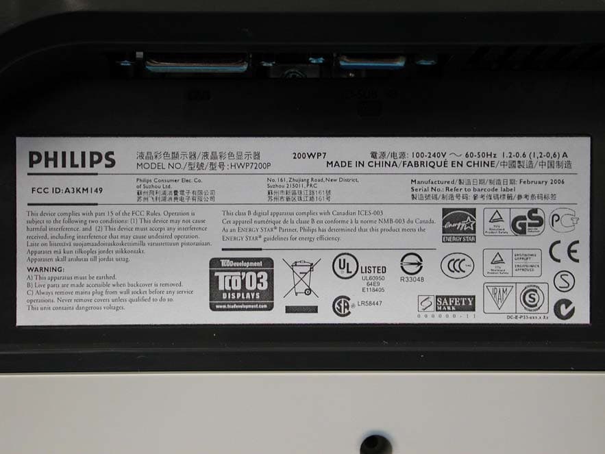
A3KM149
Mar 16, 200620� LCD Monitor
Equipment Class
JBP - Part 15 Class B Computing Device Peripheral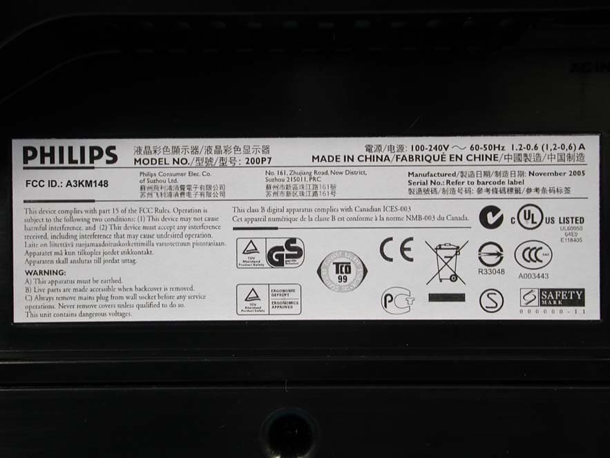
A3KM148
Dec 15, 200520
Equipment Class
JBP - Part 15 Class B Computing Device Peripheral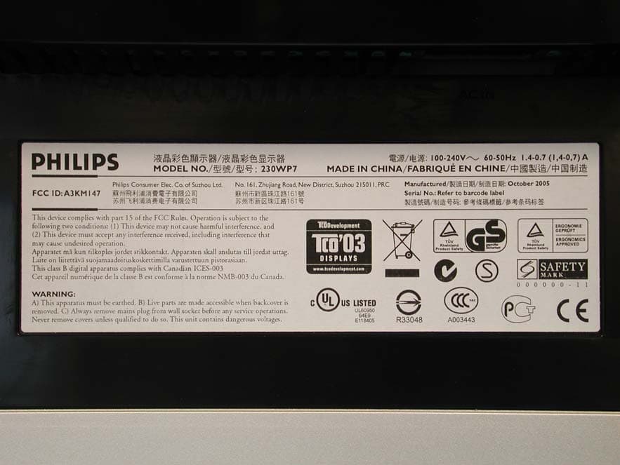
A3KM147
Nov 17, 2005LCD Monitor
Equipment Class
JBP - Part 15 Class B Computing Device Peripheral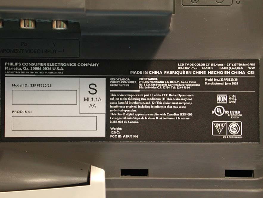
A3KM144
Jul 19, 2005LCD TV
Equipment Class
JBP - Part 15 Class B Computing Device Peripheral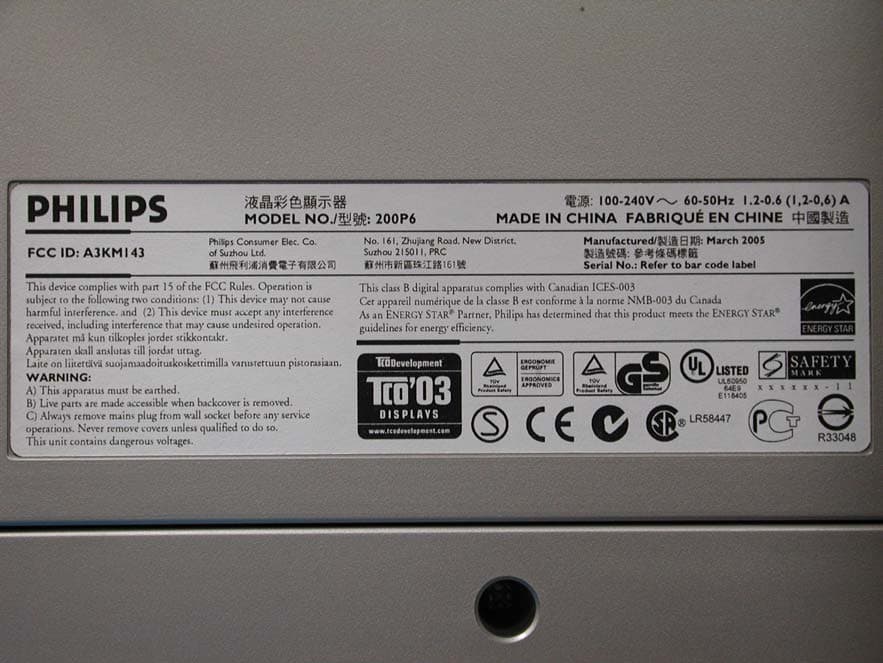
A3KM143
Apr 18, 2005Display Color Monitor
Equipment Class
JBP - Part 15 Class B Computing Device Peripheral