A3KM123Color Monitor
Philips Electronics Industries (Taiwan) Ltd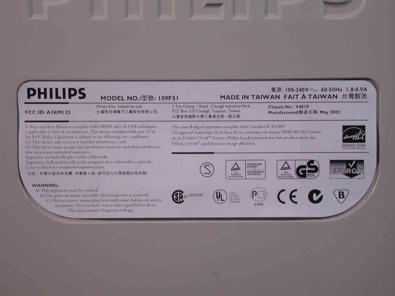
Click to zoom
Application Details
- Equipment Class
- JBP - Part 15 Class B Computing Device Peripheral
- Date of Grant
- Jun 05, 2003
- Application Purpose
- Original Equipment
- Date of Application
- Jun 05, 2003
- Equipment Note
- Color Monitor
- Country
- Taiwan
Documents & Files
Document Text
Text extracted from the exhibit documents filed with the FCC. Open a document above to read the original.
Users Manual
Product Information Product Features • Technical Specifications • Automatic Power Saving • Physical Specification • Pin Assignment • Product Views Product Features 109F5 z 19-inch (18.0" VIS) color monitor with excellent front of screen performance for use with MACs and PCs z Autoscan covers horizontal frequencies up to 92 kHz offering a maximum resolution of 1920 x 1440 with flicker free display of 1280 x 1024 up to 86 Hz z Flat Square High Contrast CRT with 0.26 mm pitch (0.23 hdp) z XSD-Xtra Space Design for large screen display in a small footprint: 19-inch conventional monitor with maximum depth of only 437 mm/17.2" z Multimedia Base and USB Hub option z sRGB for true on screen color representation. z FCC, CE (in selected countries only) and ISO9241, ISO14001 certified RETURN TO TOP OF THE PAGE Technical Specifications* CRT • Size and deflection 19 inch / 46 cm ; 90° deflection angle • Dot pitch0.26 mm • Horizontal pitch0.23 mm • Tube type Shadow mask, real flat, high contrast, anti-glare, anti- static, anti reflection, light transmission 52% • PhosphorP22 • Recommended display area14.0" x 10.4" / 355 x 265 mm • Maximum display area14.4" x 10.8" / 365 x 270 mm SCANNING • Horizontal scanning30 - 92 KHz • Vertical scanning50 - 160 Hz VIDEO • Video dot rate158 MHz • Input impedance - Video75 ohm - Sync2.2 kOhm Exhibit 3 Installstion and Operating Instructions * These information are subject to change without notice. RETURN TO TOP OF THE PAGE Automatic Power Saving If you have VESA's DPMS compliance display card or software installed in your PC, the monitor can automatically reduce its power consumption when not in use. And if an input from a keyboard, mouse or other input device is detected, the monitor will automatically "wake up". The following table shows the power consumption and signaling of this automatic power saving features: • Input signal levels0.7 Vpp • Sync input signal Separate sync Composite sync • Sync polaritiesPositive and negative WHITE COLOR TEMPERATURE Chromaticity CIE coordinates: • at 9300 degrees Kx = 0.283 / y = 0.297 • at 6500 degrees Kx = 0.313 / y = 0.329 sRGB sRGB is a standard for ensuring correct exchange of colors between different devices (e.g. digital cameras, monitors, printers, scanners, etc.) Using a standard unified color space, sRGB will help represent pictures taken by an sRGB compatible device correctly on your sRGB enabled Philips monitors. In that way, the colors are calibrated and you can rely on the correctness of the colors shown on your screen. Important with the use of sRGB is that the brightness and contrast of your monitor is fixed to a predefined setting as well as the color gamut. Therefore it is important to select the sRGB setting in the monitor's OSD. To do so, open the OSD by pressing the OK button on the front of your monitor. Use the down button to go to Color temperature and press OK again. Then move the down button to go to sRGB and press OK again. Exit this OSD. After this, please don't change the brightness or contrast setting of your monitor. If you change either of these, the monitor will exit the sRGB mode and go to a color temperature setting of 6500K. For more information on sRGB, please visit: www.srgb.com Power Management Definition VESA's Video H-sync V-sync Power Power Saving LED RETURN TO TOP OF THE PAGE Physical Specifications * These information are subject to change without notice. RETURN TO TOP OF THE PAGE Pin Assignment The 15-pin D-sub connector (male) of the signal cable (IBM systems): Mode Used (%) color ON Active Yes Yes Typical 65W 0 % Green OFF Blanked No No < 2W 97% Flashing Green This monitor is E NERGY S TAR ® compliant. A s an E NERGY S TAR ® P artner, PHILIPS has determined that this product meets the E NERGY S TAR ® guidelines for energy efficiency. • Dimensions 17.3" x 17" x 17.2" / 440 x 433 x 437 mm (including base) 17.3" x 15" x 17.2" / 440 x 383 x 437 mm (excluding base) • Weight17.8 kg • Power supply90 - 264 VAC, 50/60Hz • Temperature (operating) 0° to 40°C / 32° to 104°F • Temperature (storage) -25° to +65°C / -13° to +149°F • Relative humidity (storage) 5% to 95% * Resolution 1280 x 1024, standard size, contrast max., brightness 50%, 9300 ° , full white pattern. RETURN TO TOP OF THE PAGE Views Follow the links to see various views of the monitor and its components. Front View Rear View RETURN TO TOP OF THE PAGE Pin No. Assignment Pin No. Assignment 1 Red video input 9 No pin 2 Green video input 10 Logic ground 3 Blue video input 11 Identical output - connected to pin 10 4 Identical output - connected to pin 10 12 Serial data line (SDA) 5 Ground 13 H. Sync / H+V 6 Red video ground 14 V. Sync (VCLK for DDC) 7 Green video ground 15 Data clock line (SCL) 8 Blue video ground Installing your Monitor Front View • Rear View • 6G3B11 Multimedia Base (option) Front View RETURN TO TOP OF THE PAGE Rear View Power button switches your monitor on. OK button which when pressed will take you to the OSD controls Contrast hotkey. When the "-" button is pressed, the adjustment controls for the CONTRAST will show up. Brightness hotkey. When the "+" button is pressed, the adjustment controls for BRIGHTNESS will show up. "-" and "+" buttons, are used for adjusting the OSD of your monitor. 1. Power in - attach power cable here. 2. Video In - this is a cable which is already attached to your monitor. Connect the other end of the cable to your PC. RETURN TO TOP OF THE PAGE Energy Star Declaration PHILIPS 109E5* RETURN TO TOP OF THE PAGE Federal Communications Commission (FCC) Notice (U.S. Only) z Reorient or relocate the receiving antenna. z Increase the separation between the equipment and receiver. z Connect the equipment into an outlet on a circuit different from that to which the receiver is connected. z Consult the dealer or an experienced radio/TV technician for help. Use only RF shielded cable that was supplied with the monitor when connecting this monitor to a computer device. This monitor is equipped with a…
Text truncated - open the document above for the full version.
Block Diagram
1 V40 109F5 Circuit Brief 0. Functional Block Diagram 1. General Description 2. Description of Circuit Diagram A. Power Supply & Power Saving Management B. Horizontal Deflection/Vertical Deflection/EHT Generator C. Video board & DDC 2B D. Digital Circuit & Micro-controller Exhibit 4 2 GENERAL DESCRIPTION V40 109F5, using 19” flat high brightness CRT, are so-called “Digital Controlled Auto-scan Color Display Monitor” with high resolution which can operate at horizontal scan frequency from 30KHz up to 92KHz, and vertical scan frequencies from 50 to 160 Hz. The monitor is equipped with an embedded micro-controller, which can preset the required modes. It also provides many functions, such as digital adjustable picture, DDC2B, power management, sRGB, low emission, high immunity, ---- etc. The monitor complies with MPRII low emission standard and also fulfill E2000 automatic power saving requirements, to reduce power consumption to less than 2 watts in power saving mode. The monitor also complies with VESA standard and energy star computer program initiated by the EPA. 1. DESCRIPTION OF CIRCUIT DIAGRAM This description mainly introduces the functions including power supply, power saving management, horizontal / vertical deflection, video amplifier, and micro- controller, etc. A. POWER SUPPLY / POWER SAVING MANAGEMENT The monitor is designed to adopt switching mode power supply which can operate mains input from 90VAC to 264VAC. This switching power supply applies an IC TEA1507. The control scheme transforms a rectified voltage source into a multi-output voltages. The control concept exhibits many desirable properties such as inherent over-load protection, stable and fast system response. A current sense circuit (R3107/08/09, etc) is equipped for power limiting (90W) and safety reason on primary power supply circuit. Secondary feedback via a photo-coupler is used to obtain a stable output voltage. The secondary outputs supply all necessary voltages for deflection and video and micro-controller. All rectified diodes on secondary site are without lead frame ( heat-sink), it gains some cost saving in thermal design, but the turn ratios of main transformer should be well determined to maintain an adequate voltage derating of primary switching MOSFET and secondary +197V rectified diode BYV36C (with better thermal performance).This is trade-off design in between. The other hand, a secondary DC power switch is also adopted. And for cost saving B+197V adjust VR is replaced with two fixed resistors (3144,3145). This monitor can save power consumption while no sync pulses and automatically recover to normal power-on when sync signals are detected by micro-controller. The power saving off mode still exists in new designed monitors, but suspend / stand-by mode are deleted due to patent infringement issue. During Off mode, LED will flash and all the output voltages of main power are reduced to a very low level, and the operating frequency also comes very low, and only the required voltage of micro- controller (+5V) is supplied. When the monitor is switched off it is actually in burst mode (< 2W). B. HORIZONTAL DEFLECTION / VERTICAL DEFLECTION / EHT GENERATOR 3 HORIZONTAL DEFLECTION: The heart of horizontal/vertical deflection controller is TDA4841, which can offer a complete and efficient small signal sync processing for auto-sync monitors. All functions are controlled via I2C bus. This controller provides sync processing, which can accept separate and composite (H+V) input signals. A very short settling time after mode change for protection of external power components has been taken into account. However, it should be noted that according to V40 109F5 spec this monitor doesn’t support composite (H+V) input signals to avoid some troubles. The TDA4841 provides extensive functions like a flexible B+ controller block of H-deflection and a geometry control with facility, leading to excellent picture quality. This device also can directly drive the vertical deflection output stage. The line driver stage, the E/W output stage and all controls are tracked with the incoming frequencies. Picture can be adjusted along horizontal/vertical direction by OSD H-shift/V-shift control. The horizontal size, east/west, trapezoid corrections can be adjusted by the output of pin24 (EWout), which is led to the diode modulation circuit. S-capacitors plus power MOSFET switches and DC controlled linearity coil are designed for optimal picture linearity. VERTICAL DEFLECTION: The majority of vertical deflection function is integrated by two ICs : TDA4841and TDA8172. The TDA4841 takes care of sync polarity correction, automatic catching and holding of the vertical oscillator, generation of saw-tooth drive current for vertical output and vertical s-correction, and generation of a correct V-blanking pulse for video blanking during vertical retrace time. The TDA8172 is a DC-coupled vertical deflection booster with differential input signals, suitable for color monitors. The output stage has thermal and soar protection, and high linear saw-tooth signal amplification to obtain the required vertical deflection current. The voltage supply at flyback time for output stage is generated by the internal flyback generator and the external diode (6401) and capacitor (2405) which make the so-called pump-up circuit. EHT GENERATOR The IC TDA4841 is also used as a controller to generate required extra high voltage for CRT via a buck converter (7603) which supplies the required B+ to LOT’s primary. This is a conventional combination circuit of horizontal deflection and EHT generation. Flyback transformer (LOT) transfers the primary voltage to the required anode voltage and rest tertiary output voltages. The adjustable focus (G3) and screen (G2) voltages are internally derived from the anode voltage. Another secondary winding is used to generate the voltage for G1. Dynamic focus on G4 is derived from a DAF transformer (5671) to get a good focus perfor…
Text truncated - open the document above for the full version.
External Photos
Exhibit 7 Photographs Front View Rear View Label
ID Label/Location Info
Exhibit 2 FCC ID Label
Internal Photos
Top View Without Back Cover Side View Without Back Cover Side View Without Back Cover Shielding CRT Assembly PCB Layout PCB Layout PCB Layout PCB Layout Plate Power Cord and I/F Cables
Test Report
Philips Electronics Industries (Taiwan) Ltd - EMC Lab. 5, Tze Chiang 1 Road, Chungli Industrial Park, Chungli, Taoyuan, Taiwan Tel.: +886-3-454-9862 Fax.: +886-3-454-9887 E-mail: [email protected] FCC Test Report Report No.: TYR87-2048 Date : 05 June, 2003 Page : Page 1 of 35 Customer : Philips Electronics Industries Name : Mr. S.T. Huang – EE LCD Address : 5, Tze Chiang 1 Road, Zip/City : Chungli Industrial Park, Country : Chungli, Taiwan, R.O.C. Equipment Under Test (including peripherals) : FCC ID. : A3KM123 Model Name : 109F51 Serial Number : TY0304253 Description : 19” XGA color monitor, Max. resolution 1920x1440/60Hz EMC Standards : FCC Part 15 of October 01,1999 Class B ANSI C63.4-1992 Result : PASSED the limits/test-levels in the standards. Note : The results in this report apply only to the sample(s) and mode(s) tested. It is the manufacturer’s responsibility to assume the continued EMC compliance of production models. Date of receipt of EUT : 19 May 2003 Date of performance of test : 21 May, 2003 to 23 May, 2003 Philips Electronics Industries (Taiwan) Ltd This report shall not be reproduce except in full, without written approval of the testing laboratory C.C. Wu - EMC Test Engineer Ronnie Yang - EMC Manager Reference: TYR87-2048 109F51 Date: 05 June 2003 Philips Electronics Industries (Taiwan) Ltd Page: 2 of 35 Table of contents 1. Summary of test results.............................................................................3 2. General information of EUT.......................................................................4 3. Test equipment.......................................................................................5 4. Test configuration of EUT and peripherals......................................................6 5. Test procedure.......................................................................................7 6. Measurement uncertainty...........................................................................9 7. Conducted emissions test..........................................................................10 8. Radiated emissions test............................................................................19 9. Photographs of test set-up.........................................................................31 10. References...........................................................................................35 Reference: TYR87-2048 109F51 Date: 05 June 2003 Philips Electronics Industries (Taiwan) Ltd Page: 3 of 35 1. Summary of test results Test Standard Result Note Emission, ANSI C63.4-1992 Conducted emission Radiated emission FCC Part 15 FCC Part 15 Passed Passed Remark: The test sample fully complies with the requirements set forth in : FCC Part 15 Class B. Reference: TYR87-2048 109F51 Date: 05 June 2003 Philips Electronics Industries (Taiwan) Ltd Page: 4 of 35 2. General Information of EUT The EUT, 19” color monitor : Model No. : 109F51 FCC ID : A3KM123 Brand : PHILIPS The color monitor automatically scans horizontal frequencies between 30KHz and 92KHz , and vertical frequencies between 50Hz and 160Hz. This color monitor displays sharp and brilliant images of text and graphics with a maximum resolution up to 1920x1440 pixels. The monitor has 7 factory-preset modes as indicated in the following table: Resolution modes H. freq. V. freq. H. V. 1. 720 x 400 31.5 Khz 70 Hz (VESA) - + 2. 800 x 600 46.9 Khz 75 HZ(VESA) Don’t Care 3. 800 x 600 53.7 Khz 85 HZ(VESA) Don’t Care 4. 1024 x 768 60.0 Khz 75 HZ(VESA) Don’t Care 5. 1024 x 768 68.7 Khz 85 HZ(VESA) Don’t Care 6. 1280 x 1024 80.0 Khz 75 Hz (VESA) Don’t Care 7. 1280 x 1024 91.2 Khz 85 Hz (VESA) Don’t Care Reference: TYR87-2048 109F51 Date: 05 June 2003 Philips Electronics Industries (Taiwan) Ltd Page: 5 of 35 3. Test Equipment Test equipment used for line Conducted and Radiated emissions as following. All equipment were calibrated according to ANSI C63.4-1992 and ISO-9000 requirement unless otherwise specified. Traceability to R.O.C. and international standards is assured by using calibrated all equipment. - For Conducted Emissions Test: Test Equipment Model No. Serial No. Last Calibrate Next Calibrate Spectrum HP8568B 2928A04640 06/27/2002 06/27/2003 EMI Receiver R & S ESVS30 841977/006 06/13/2002 06/13/2003 LISN EMCO 3825/2 9311-2153 06/13/2002 06/13/2003 LISN EMCO 3825/2 9311-2154 06/13/2002 06/13/2003 RF Cable 8-meter N/A 09/15-2002 09/15/2003 - For Radiated Emissions Test: Test Equipment Model No. Serial No. Last Calibrate Next Calibrate Spectrum HP8568B 2928A04640 06/27/2002 06/27/2003 RF Preselector HP85685A 2620A00338 06/27/2002 06/27/2003 QP Adapter HP85650A 2811A01324 06/27/2002 06/27/2003 EMI Receiver R & S ESVS30 841977/006 06/13/2002 06/13/2003 Biconical Antenna EMCO 3110B 3224 09/19/2002 09/19/2003 Log-Periodic Antenna EMCO 3146A 1425 09/19/2002 09/19/2003 Turn Table EMCO 1060 1068 09/15/2002 09/15/2003 Antenna Tower EMCO 1050 1113 09/15/2002 09/15/2003 RF Cable M17/75-RG214-NE N/A 09/15/2002 09/15/2003 Reference: TYR87-2048 109F51 Date: 05 June 2003 Philips Electronics Industries (Taiwan) Ltd Page: 6 of 35 4. Test Configuration of EUT and Peripherals The system was configured for testing in a typical fashion ( as a customer would normally use it ) according to ANSI C63.4-1992, please see the photographs for detail. For system measurement, the EUT “109F51” were connected to: Description Brand/ Model No. Serial No. FCC ID Remark A Monitor Philips 109F51 TY034253 A3KM123 EUT B PC Compaq ENC P866 5K15FXHZ2013 FCC Logo C Keyboard Compaq KB-9963 B26950GGALP13Q FCC Logo D Mouse Compaq M-S48a JNZ201213 E Modem Hayes 231AA A22231081770 BFJ9D9308US F Printer HP 2225C 2934S55406 DSI6XU2225 Connected Cables No. Description Manufacturer Length Shielded Remark 1 Power Cord Long Shine 1.8 meters No for EUT 2 Power Cord Acer 1.8 meters No for PC 3 Power Cord Aceex 2.0 meters No for Modem 4 Power Cord HP 1.8 meters No for Printer 5 Video Cable Long Shine 1.5 meters Yes 6 Printer C…
Text truncated - open the document above for the full version.
Test Setup Photos
Reference: TYR87-2048 109F51 Date: 05 June 2003 Philips Electronics Industries (Taiwan) Ltd Page: 31 of 35 9. Photographs of Test Set-up Conducted Emissions Test Reference: TYR87-2048 109F51 Date: 05 June 2003 Philips Electronics Industries (Taiwan) Ltd Page: 32 of 35 Conducted Emissions Test Reference: TYR87-2048 109F51 Date: 05 June 2003 Philips Electronics Industries (Taiwan) Ltd Page: 33 of 35 Radiated Emissions Test Reference: TYR87-2048 109F51 Date: 05 June 2003 Philips Electronics Industries (Taiwan) Ltd Page: 34 of 35 Radiated Emissions Test Reference: TYR87-2048 109F51 Date: 05 June 2003 Philips Electronics Industries (Taiwan) Ltd Page: 35 of 35 10. Reference FCC part 15 - 1999 Radio frequency device. ANSI C63.4-1992, “American national standard for measurement of radio-noise emission from low-voltage electrical and electronic equipment in the range of 9KHz to 40GHz”
Contact Information
Applicant
Ronnie Yang(Manager, Safety/DEV)
Test Firm
Philips Electronics Industries (Taiwan) Ltd.Ronnie Yang
Technical Specifications
| # | Rule Parts | Frequency Range | Power Output |
|---|---|---|---|
| 1 | 15B | - | - |
Other Applications from Philips Electronics Industries (Taiwan) Ltd
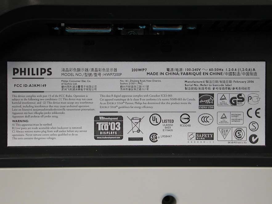
A3KM149
Mar 16, 200620� LCD Monitor
Equipment Class
JBP - Part 15 Class B Computing Device Peripheral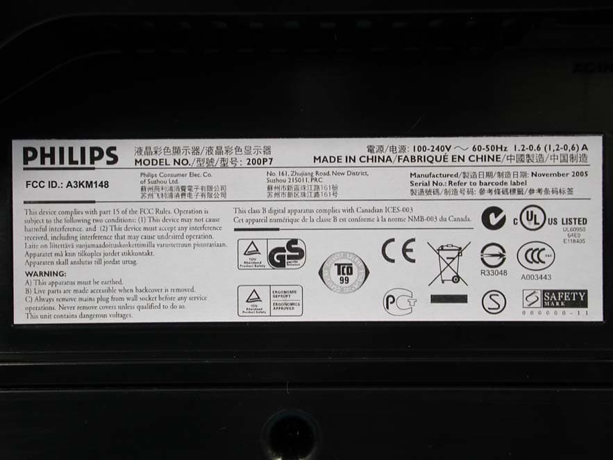
A3KM148
Dec 15, 200520
Equipment Class
JBP - Part 15 Class B Computing Device Peripheral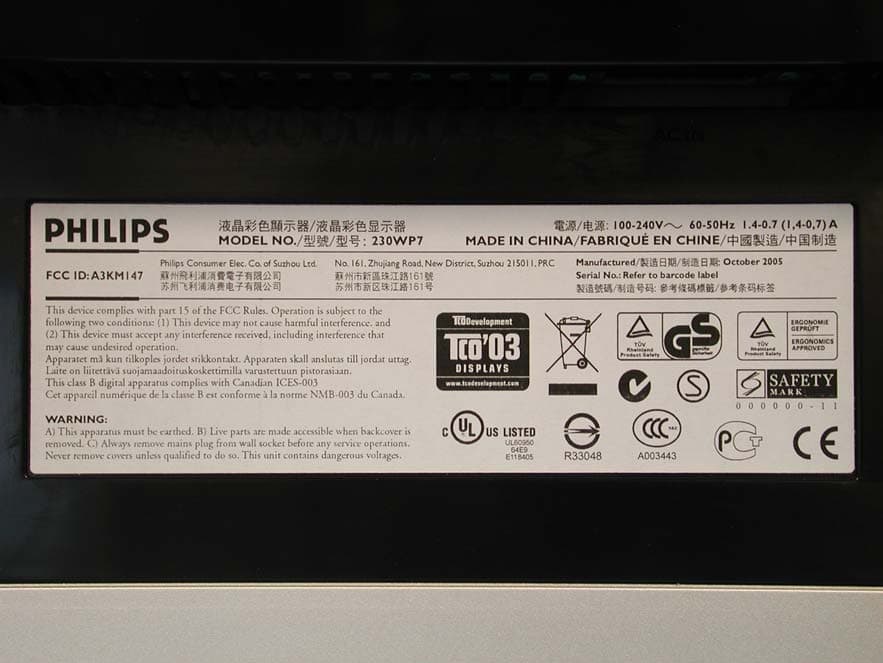
A3KM147
Nov 17, 2005LCD Monitor
Equipment Class
JBP - Part 15 Class B Computing Device Peripheral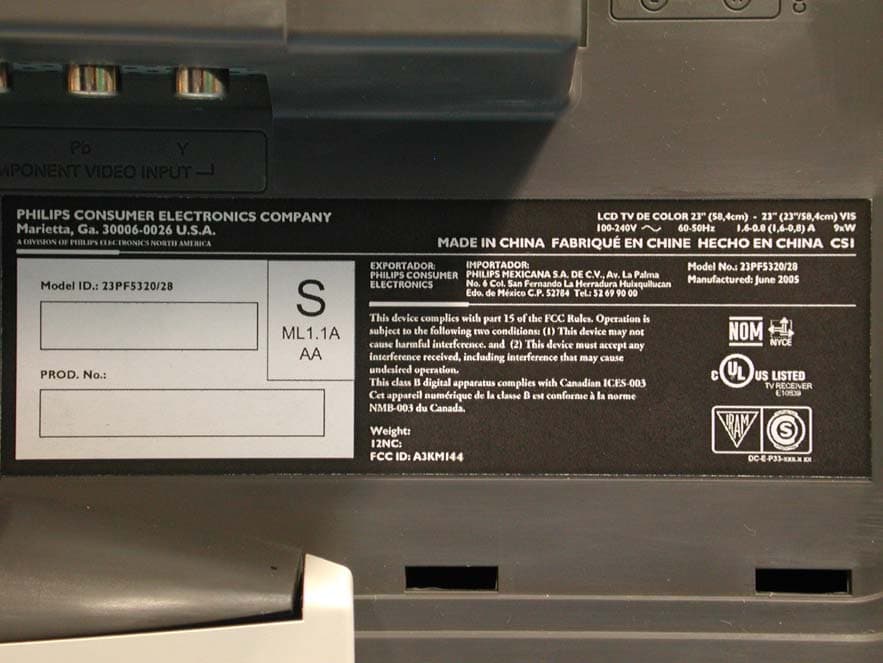
A3KM144
Jul 19, 2005LCD TV
Equipment Class
JBP - Part 15 Class B Computing Device Peripheral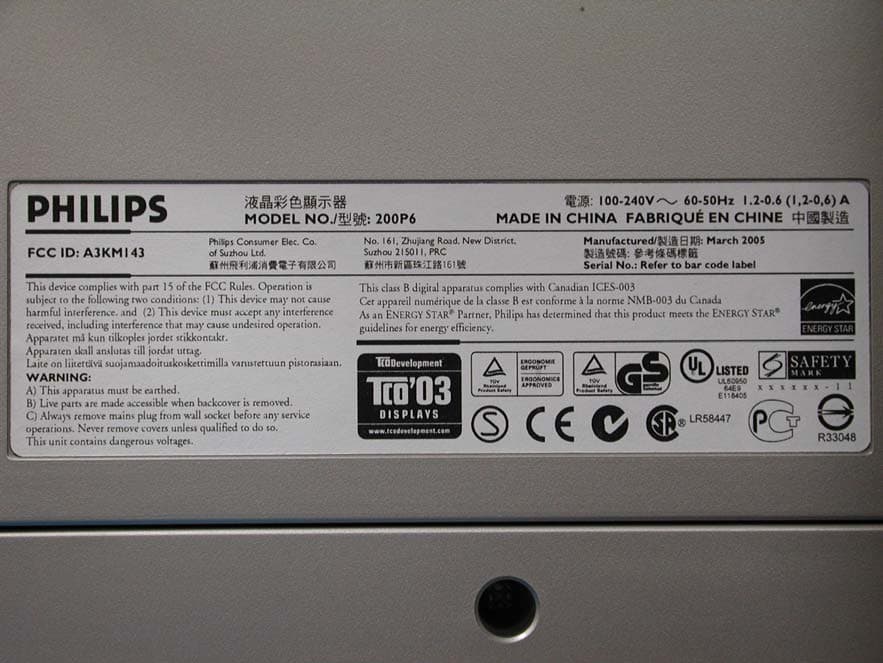
A3KM143
Apr 18, 2005Display Color Monitor
Equipment Class
JBP - Part 15 Class B Computing Device Peripheral