A3KM12717 Inches LCD Color Monitor
Philips Electronics Industries (Taiwan) Ltd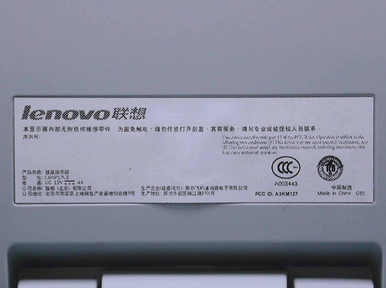
Click to zoom
Application Details
- Equipment Class
- JBP - Part 15 Class B Computing Device Peripheral
- Date of Grant
- Nov 23, 2003
- Application Purpose
- Original Equipment
- Date of Application
- Nov 23, 2003
- Equipment Note
- 17 Inches LCD Color Monitor
- Country
- Taiwan
Documents & Files
Document Text
Text extracted from the exhibit documents filed with the FCC. Open a document above to read the original.
Users Manual
Before operating the monitor please read this manual thoroughly. This manual should be retained for future reference. FCC Class B Radio Frequency Interference Statement WARNING: (FOR FCC CERTIFIED MODELS) NOTE: This equipment has been tested and found to comply with the limits for a Class B digital device, pursuant to Part 15 of the FCC Rules. These limits are designed to provide reasonable protection against harmful interference in a residential installation. This equipment generates, uses and can radiate radio frequency energy, and if not installed and used in accordance with the instructions, may cause harmful interference to radio communications. However, there is no guarantee that interference will not occur in a particular installation. If this equipment does cause harmful interference to radio or television reception, which can be determined by turning the equipment off and on, the user is encouraged to try to correct the interference by one or more of the following measures: 1. Reorient or relocate the receiving antenna. 2. Increase the separation between the equipment and receiver. 3. Connect the equipment into an outlet on a circuit different from that to which the receiver is connected. 4. Consult the dealer or an experienced radio/TV technician for help. NOTICE 1. The changes or modifications not expressly approved by the party responsible for compliance could void the user's authority to operate the equipment. 2. Shielded interface cables and AC power cord, if any, must be used in order to comply with the emission limits. 3. The manufacturer is not responsible for any radio or TV interference caused by unauthorized modification to this equipment. It is the responsibilities of the user to correct such interference. WARNING: To prevent fire or shock hazard, do not expose the monitor to rain or moisture. Dangerously high voltages are present inside the monitor. Do not open the cabinet. Refer servicing to qualified personnel only. Exhibit 3 Installstion and Operating Instructions SPECIAL NOTES ON LCD MONITORS The following symptoms are normal with LCD monitor and do not indicate a problem. NOTES • Due to the nature of the fluorescent light, the screen may flicker during initial use. Turn off the Power and then turn it on again to make sure the flicker disappears. • You may find slightly uneven brightness on the screen depending on the desktop pattern you use. • The LCD screen has effective pixels of 99.99% or more. It may include blemishes of 0.01% or less such as a missing pixel or a pixel lit all of the time. • Due to the nature of the LCD screen, an afterimage of the previous screen may remain after switching the image, when the same image is displayed for hours. In this case, the screen is recovered slowly by changing the image or turning off the Power for hours. • The life of the fluorescent light used in the LCD monitor is approximately 20,000 hours. Contact your dealer or service center for replacement when the screen is dark, flickering or not lighting up. Never attempt to replace it by yourself. BEFORE YOU OPERATE THE MONITOR FEATURES • 43.2cm(17”) TFT Color LCD Monitor • Crisp, Clear Display for Windows • Supports Resolutions up to 1280 X 1024@75Hz • Screen Saver • Ergonomic Design (TCO’95 Approved) • Space Saving, Compact Case Design CHECKING THE CONTENTS OF THE PACKAGE The product package should include the following items: 1. LCD Monitor 2. Owner's Manual 3. DC-12V Power Cord 4. Base INSTALLATION INSTRUCTIONS Install 1 2 Remove 1 2 Power Cord 1. Make sure the power cord is the correct type that required in your area. 2. This monitor has a universal power supply that allows operation in either 100/120V AC or 220/240V AC voltage area ( No user adjustment is required. ) Power Source: This LCD monitor has been applied DC+12V. It connects with PC and monitor. CONTROLS AND CONNECTORS VIDEO CABLE Connecting the Video Cable: the LCD monitor comes with a fly-in video cable. Plug the signal cable ′ s 15-pin connector into the computer's video port and tighten the two screws on the cable connector. Figure 1 Connecting Cables ADJUSTING THE VIEWING ANGLE • For optimal viewing it is recommended to look at the full face of the monitor, then adjust the monitor’s angle to your own preference. • Hold the stand so you do not topple the monitor when you change the monitor’s angle. • You are able to adjust the monitor’s angle from -5 ° to 25 ° . DC-12V Power Cable Signal Cable Figure 2 NOTES • Do not touch the LCD screen when you change the angle. It may cause damage or break the LCD screen. • Careful attention is required not to catch your fingers or hands when you change the angle. APPENDIX SPECIFICATIONS Driving systemTFT Color LCD LCD Panel Size 43.2 cm(17") Pixel pitch 0.264 mm( H )x 0.264mm( V ) Viewable angle 140 ° (H) 140 ° (V) Response time16 ms Video R,G,B Analog Interface Input Separate Sync.H/V TTL H-Frequency 30kHz - 80kHz V-Frequency 50Hz-75Hz Display Colors 16.7M Colors Dot Clock 135MHz Max. Resolution 1280 x 1024 Plug & Play VESA DDC2B TM Input Connector D-Sub 15pin Input Video Signal Analog:0.7Vp-p(standard), 75 OHM, Positive Maximum Screen Size Horizontal : 337.9mm Vertical : 270.3mm Power Source DC+12V , 4A Environmental Considerations Operating Temp: 32°F to 97.6°F (0°C to 40°C) Storage Temp. -46.7°F to 140°F (-20°C to 60°C) Operating Humidity : 10% to 85% Weight (N. W.) 3.8Kg Switch • Auto Adjust Key • / Brightness • / Contrast • Power /Power indicator • MENU External Controls: Functions • Language • Adjust Position • Bright & Contrast • Video Noise • Adjust Color • OSD Settings • OSD Timer • Exit Main Controls • Reset to factory settings Power Consumption ( Max ) ≤ 42W Regulatory Compliance FCC,TCO’95, CCC FACTORY PRESET TIMING TABLE STANDARD RESOLUTION HORIZONTAL FREQUENCY VERTICAL FREQUENCY VGA 640 x 350 31.469kHz 70.087Hz TV signal 640 × 480 31.25kHz 50.0Hz VGA 640 × 480 31.469kHz 59.94Hz VESA 640 × 480 37.861kHz 72.809Hz VESA 640 × 480 37.5kHz 75.0Hz VGA 720 × …
Text truncated - open the document above for the full version.
Block Diagram
Exhibit 4 Brief Description of Circuit Functions Function Description for Hudson III-Lenovo Helen 17” 1. General The SXGA TFT LCD monitor is specified as a display peripheral with analog (DSUB). Horizontal scan range is 30KHz-82KHz and the refresh range is 50Hz-76Hz in normal mode. This scan range allows it to display resolution up to 1280x1024x75Hz non-interlace input. The image can be adjusted by OSD control. These adjustments can be stored in an onboard memory. 2. Power supply Main voltage : DC 12V (From PC side: Lenovo power supply) Power consumption : 45W Max. Power indicator : LED(ON: blue, Sleep: amber) Auto power saving : VESA DPMS 3. Input signal Horizontal scan : 30-82KHz Vertical scan : 50-76Hz Input signals : A. D-SUB signal input level Video : 0.7Vp-p linear/75 ohms Sync : H,V TTL level 4. OSD( On Screen Display) function Software control function via OSD -Main controls: Language----------------- Simple Chinese; English Brightness & Contrast-- Brightness, Contrast Video Settings -------------- Phase; Clock; H&V Position Color Temp.-------------- 7800K, 6500K, User OSD Settings------------- H&V Position; Timer Product information----- Resolution, Refresh rate Reset to factory setting; Exit Main controls 5. LCD Panel Type : 17” TFT LCD flat panel Dimensions : 17”(358.5 x 296.5 x 19 mm) Pitch : 0.264mmx0.264mm Color pixel arrangement : RGB vertical stripes Number of color : 64 gray level (6 bits) Backlight : 4 CCFL’s Active area (W*H) : 337.92 x 270.5mm 6. Function block Scaler GM2126 (contains following functions): (1) Analog RGB input - Support up to SXGA 75Hz - On chip high-performance PLLs - High speed triple ADC (3) Format converter - Built in GPIO port, mode detection. - Convert the image data from ADC, Video Decoder to LCD panel data format. - Zoom the input video to full screen display. - High quality zoom and shrink scaling engine (4) RXDS - Convert digital image signal to RSDS signal, it can reduce EMI. (5) On-Screen display (OSD) controller (6) On-chip microcontroller (OCM) (7) Programmable OnPanel timing Controller (TCON) Inverter - Accept +12VDC voltage. - Provide 680Vrms voltage for CCFL. converter - Accept +12VDC voltage. - Convert +12V to +3.3V. Hudson III Lenovo Helen 17” Circuit Architeture DC 12V DDC_A M24C02 DSUB Connector 30 Pin Connector Inverter CLK: 50KHz Control Board KEY & LED R G B Input Regulator IRU1206 Schmitt 74LC14APW- T TCON Signal EEPROM M24C16 FLASH M29W010 Data Address Gm2126 Triple ADC and PLL 8051 Micro- Controller Panel Timing Control RSDS TX Front RGB RSDS Back RGB RSDS HS and VS 3.3V 3.3V 2.5V 3.3V and 12V Clock 14.318MHz Brightness/BL-EN Panel Power MOSFET Switch 12V/3.3V Panel Control Signal Reset IC SA56616- 28 Control Signal Converter (+12V to +3.3V) CLK: 380KHz 50 Pin Connector TFT LCD MODULE Exhibit 5
External Photos
Exhibit 7 Photographs Front View Rear View Label
ID Label/Location Info
Exhibit 2 FCC ID Label
Internal Photos
Assembly w/o Front cabinet Assembly w/o Back Cover Shielding Cover Assembly w/o Shielding Cover PCB Layout PCB Layout Plate LCD Panel AC Adapter Adapter Assembly Shielding PCB Layout PCB Layout Power Cord and I/F Cables
Test Report
Philips Electronics Industries (Taiwan) Ltd - EMC Lab. 5, Tze Chiang 1 Road, Chungli Industrial Park, Chungli, Taoyuan, Taiwan Tel.: +886-3-454-9862 Fax.: +886-3-454-9887 E-mail: [email protected] FCC Test Report Report No.: TYR87-2058 Date : 18 October, 2003 Page : Page 1 of 32 Customer : Philips Electronics Industries Name : Mr. S.T. Huang – EE LCD Address : 5, Tze Chiang 1 Road, Zip/City : Chungli Industrial Park, Country : Chungli, Taiwan, R.O.C. Equipment Under Test (including peripherals) : FCC ID. : A3KM127 Model Name : LXH-P17L3 Serial Number : TY0304669 Description : 17” SXGA LCD color monitor, Max. resolution 1280x1024/75Hz EMC Standards : FCC Part 15 of October 01,1999 Class B ANSI C63.4-1992 Result : PASSED the limits/test-levels in the standards. Note : The results in this report apply only to the sample(s) and mode(s) tested. It is the manufacturer’s responsibility to assume the continued EMC compliance of production models. Date of receipt of EUT : 14 Nov. 2003 Date of performance of test : 15 Nov., 2003 to 17 Nov., 2003 Philips Electronics Industries (Taiwan) Ltd This report shall not be reproduce except in full, without written approval of the testing laboratory C.C. Wu - EMC Test Engineer Ronnie Yang - EMC Manager Reference: TYR87-2055 LXH-P17L3 Date: 18 November 2003 Philips Electronics Industries (Taiwan) Ltd Page: 2 of 32 Table of contents 1. Summary of test results.............................................................................3 2. General information of EUT.......................................................................4 3. Test equipment.......................................................................................5 4. Test configuration of EUT and peripherals......................................................6 5. Test procedure.......................................................................................7 6. Measurement uncertainty...........................................................................9 7. Conducted emissions test..........................................................................10 8. Radiated emissions test............................................................................19 9. Photographs of test set-up.........................................................................28 10. References...........................................................................................32 Reference: TYR87-2055 LXH-P17L3 Date: 18 November 2003 Philips Electronics Industries (Taiwan) Ltd Page: 3 of 32 1. Summary of test results Test Standard Result Note Emission, ANSI C63.4-1992 Conducted emission Radiated emission FCC Part 15 FCC Part 15 Passed Passed Remark: The test sample fully complies with the requirements set forth in : FCC Part 15 Class B. Reference: TYR87-2055 LXH-P17L3 Date: 18 November 2003 Philips Electronics Industries (Taiwan) Ltd Page: 4 of 32 2. General Information of EUT The EUT, 17” color monitor : Model No. : LXH-P17L3 FCC ID : A3KM127 Brand : Lenovo The color monitor automatically scans horizontal frequencies between 30KHz and 80KHz , and vertical frequencies between 50Hz and 75Hz. This color monitor displays sharp and brilliant images of text and graphics with a maximum resolution up to 1280x1024 pixels. The monitor has 12 factory-preset modes as indicated in the following table: Table # Resolution H-Freq (KHz)Pixel rate (MHz) V-Freq (Hz) Comment 1 720x400 31.469 28.322 70.087 VGA 2 640x480 31.469 25.175 59.940 VGA 3 640x480 37.861 31.500 72.809 VESA 4 640x480 37.500 31.500 75.000 VESA 5 800x600 37.879 40.000 60.317 VESA 6 800x600 46.875 49.500 75.000 VESA 7 1024x768 48.363 65.000 60.004 VESA 8 1024x768 56.476 75.000 70.069 VESA 9 1024x768 60.023 78.750 75.029 VESA 10 1280x1024 63.981 108.000 60.020 VESA 11 1280x1024 79.976 135.000 75.025 VESA 12 704x574 31.250 27.000 50.000 TV-PAL Reference: TYR87-2055 LXH-P17L3 Date: 18 November 2003 Philips Electronics Industries (Taiwan) Ltd Page: 5 of 32 3. Test Equipment Test equipment used for line Conducted and Radiated emissions as following. All equipment were calibrated according to ANSI C63.4-1992 and ISO-9000 requirement unless otherwise specified. Traceability to R.O.C. and international standards is assured by using calibrated all equipment. - For Conducted Emissions Test: Test Equipment Model No. Serial No. Last Calibrate Next Calibrate Spectrum HP8568B 2928A04640 02/27/2003 02/27/2004 EMI Receiver R & S ESVS30 841977/006 02/27/2003 02/27/2004 LISN EMCO 3825/2 9311-2153 06/16/2003 06/16/2004 LISN EMCO 3825/2 9311-2154 06/16/2003 06/16/2004 RF Cable 8-meter N/A 08/21/2003 08/21/2004 - For Radiated Emissions Test: Test Equipment Model No. Serial No. Last Calibrate Next Calibrate Spectrum HP8568B 2928A04640 09/23/2003 09/23/2004 RF Preselector HP85685A 2620A00338 09/23/2003 09/23/2004 QP Adapter HP85650A 2811A01324 09/23/2003 09/23/2004 EMI Receiver R & S ESVS30 841977/006 02/27/2003 02/27/2004 Biconical Antenna EMCO 3110B 3224 08/21/2003 08/21/2004 Log-Periodic Antenna EMCO 3146A 1425 08/21/2003 08/21/2004 Turn Table EMCO 1060 1068 08/21/2003 08/21/2004 Antenna Tower EMCO 1050 1113 08/21/2003 08/21/2004 RF Cable M17/75-RG214-NE N/A 08/21/2003 08/21/2004 Reference: TYR87-2055 LXH-P17L3 Date: 18 November 2003 Philips Electronics Industries (Taiwan) Ltd Page: 6 of 32 4. Test Configuration of EUT and Peripherals The system was configured for testing in a typical fashion ( as a customer would normally use it ) according to ANSI C63.4-1992, please see the photographs for detail. For system measurement, the EUT “LXH-P17L3” were connected to: Description Brand/ Model No. Serial No. FCC ID Remark A Monitor Lenovo LXH-P17L3 TY0304669 A3KM127 EUT B PC Compaq ENC P866 5K15FXHZ2013 FCC logo C Keyboard Compaq KB-9963 B26950GGALP13Q FCC Logo D Mouse Compaq M-S48a JNZ201213 E Modem Hayes 231AA A22231081770 BFJ9D9308US F Printer HP 2225C 2934S55406 DSI6XU2225 Connected Cables No. Description Manufacturer Length Shielded Remark 1 Power Co…
Text truncated - open the document above for the full version.
Contact Information
Applicant
Ronnie Yang(Manager, Safety/DEV)
Test Firm
Philips Electronics Industries (Taiwan) Ltd.Ronnie Yang
Technical Specifications
| # | Rule Parts | Frequency Range | Power Output |
|---|---|---|---|
| 1 | 15B | - | - |
Other Applications from Philips Electronics Industries (Taiwan) Ltd
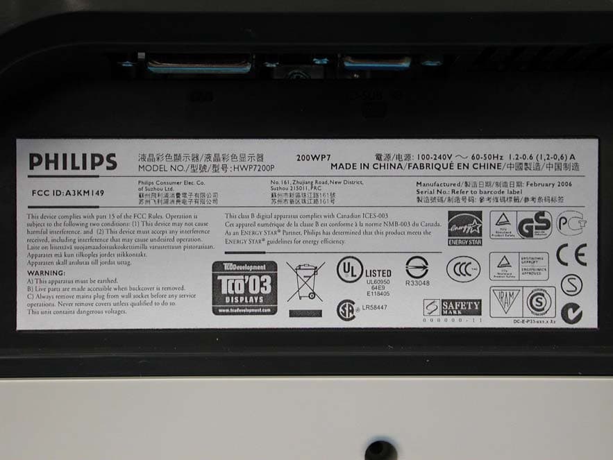
A3KM149
Mar 16, 200620� LCD Monitor
Equipment Class
JBP - Part 15 Class B Computing Device Peripheral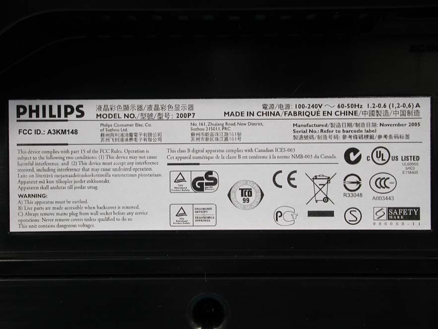
A3KM148
Dec 15, 200520
Equipment Class
JBP - Part 15 Class B Computing Device Peripheral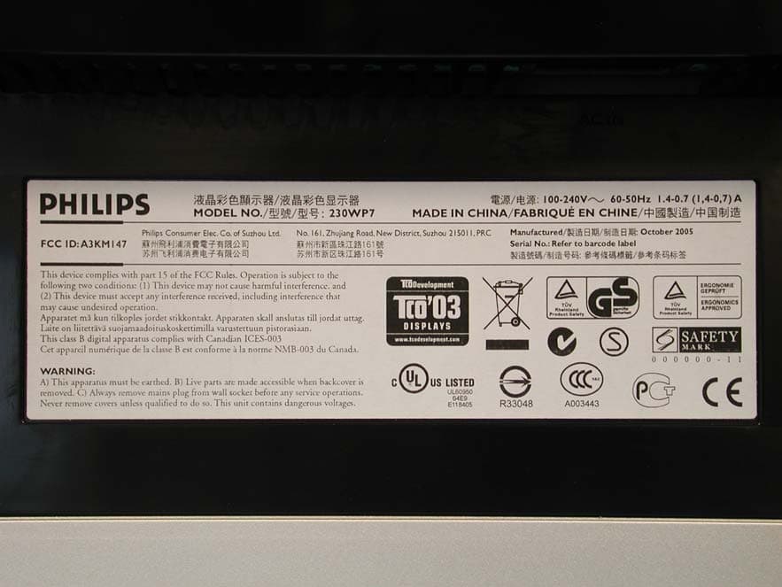
A3KM147
Nov 17, 2005LCD Monitor
Equipment Class
JBP - Part 15 Class B Computing Device Peripheral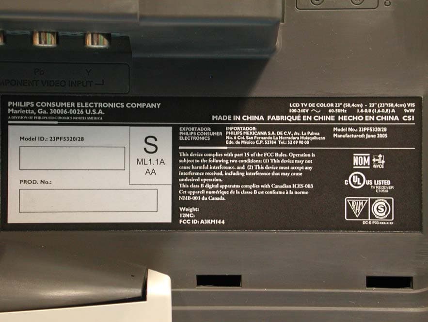
A3KM144
Jul 19, 2005LCD TV
Equipment Class
JBP - Part 15 Class B Computing Device Peripheral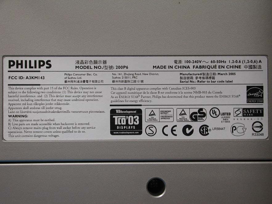
A3KM143
Apr 18, 2005Display Color Monitor
Equipment Class
JBP - Part 15 Class B Computing Device Peripheral