A3KM12917 Inches LCD Monitor
Philips Electronics Industries (Taiwan) Ltd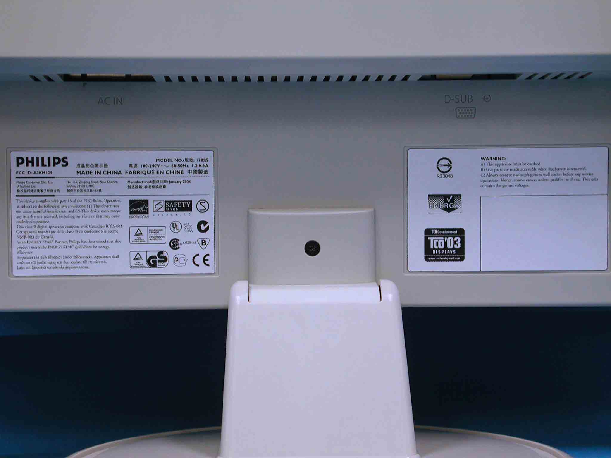
Click to zoom
Application Details
- Equipment Class
- JBP - Part 15 Class B Computing Device Peripheral
- Date of Grant
- Mar 18, 2004
- Application Purpose
- Original Equipment
- Date of Application
- Mar 18, 2004
- Equipment Note
- 17 Inches LCD Monitor
- Country
- Taiwan
Documents & Files
Document Text
Text extracted from the exhibit documents filed with the FCC. Open a document above to read the original.
Users Manual
Product Information Product Features 170S5 z Best Total Cost of Ownership solution {Lower power consumption ~ Less cost: up to 20% power savings than industry average {Kensington anti-theft lock ~ Added security prevents theft by locking monitor in place z Outstanding front of screen performance {Fast response time ~ Get the job done quicker with fast response time {SXGA, 1280 x 1024 resolution ~ Accurate color displaying more than 1.3 million pixels {sRGB ready ~ What you see is what you get: Display matches printout z Great Convenience {Embedded power supply ~ Power supply built into monitor {VESA mounting hole ~ VESA mounting pattern for easy wall mounting your display {FlexiHolder ~ Flexible card, photo, and notes holder to increase efficiency RETURN TO TOP OF THE PAGE Technical Specifications* LCD PANEL • TypeTFT LCD • Screen size17" / 43.2 cm diagonal • Pixel Pitch0.264 x 0.264 mm • LCD Panel type 1280 x 1024 pixels R.G.B. vertical stripe Anti-glare polarizer, hard coated • Effective viewing area337.9 x 270.3 mm • Display Colors16M colors SCANNING Vertical refresh rate56 Hz-76 Hz Horizontal Frequency30k Hz-82 kHz VIDEO • Video dot rate135 MHz • Input impedance - Video 75 ohm - Sync 2.2K ohm • Input signal levels0.7 Vpp • Sync input signal Separate sync Composite sync Installstion and Operating Instructions Exhibit 3 * This data is subject to change without notice. RETURN TO TOP OF THE PAGE Resolution & Preset Modes Sync on green • Sync polaritiesPositive and negative • Video interface D-Sub (analog) Optical characteristics • Contrast ratio450:1 (typ.) • Brightness 250 cd/m 2 (typ.) • Peak contrast angle6 o'clock • White Chromaticity x: 0.283 y: 0.297 (at 9300°K) x: 0.313 y: 0.329 (at 6500°K) x: 0.313 y: 0.329 (at sRGB) • Viewing Angle (C/R>5) Upper >65° (typ.) Lower > 75° (typ.) Left > 80° (typ.) Right > 80° (typ.) • Response time <16 ms (typ.) sRGB sRGB is a standard for ensuring correct exchange of colors between different devices (e.g. digital cameras, monitors, printers, scanners, etc.) Using a standard unified color space, sRGB will help represent pictures taken by an sRGB compatible device correctly on your sRGB enabled Philips monitors. In that way, the colors are calibrated and you can rely on the correctness of the colors shown on your screen. Important with the use of sRGB is that the brightness and contrast of your monitor is fixed to a predefined setting as well as the color gamut. Therefore it is important to select the sRGB setting in the monitor's OSD. To do so, open the OSD by pressing the OK button on the front of your monitor. Use the down button to go to Adjust Color and press OK again. Then move the down button to go to sRGB and press OK again. Exit this OSD. After this, please do not change the brightness or contrast setting of your monitor. If you change either of these, the monitor will exit the sRGB mode and go to a color temperature setting of 6500K. For more information on sRGB, please visit: www.srgb.com • Maximum 1280 x 1024 at 75 Hz • Recommended 1280 x 1024 at 60 Hz 16 user definable modes RETURN TO TOP OF THE PAGE Automatic Power Saving If you have VESA DPMS compliance display card or software installed in your PC, the monitor can automatically reduce its power consumption when not in use. If an input from a keyboard, mouse or other input device is detected, the monitor will 'wake up' automatically. The following table shows the power consumption and signaling of this automatic power saving feature: RETURN TO TOP OF THE PAGE 15 factory preset modes: H. freq (kHz) Resolution V. freq (Hz) 31.5 640*350 70 31.5 720*400 70 31.5 640*480 60 35.0 640*480 67 37.5 640*480 75 35.2 800*600 56 37.9 800*600 60 46.9 800*600 75 49.7 832*624 75 48.4 1024*768 60 60.0 1024*768 75 69.0 1152*870 75 71.8 1152*900 76 63.9 1280*1024 60 80.0 1280*1024 75 Power Management Definition VESA Mode Video H-sync V-sync Power Used LED color ON Active Yes Yes < 35 W Green OFF Blanked No No < 1 W Amber This monitor is ENERGY STAR ® compliant. As an ENERGY STAR ® Partner, PHILIPS has determined that this product meets the ENERGY STAR ® guidelines for energy efficiency. Physical Specifications * This data is subject to change without notice. * Resolution 1280x1024, standard size, brightness max., contrast 50%, 9300° K, full white pattern, without audio/USB. RETURN TO TOP OF THE PAGE Pin Assignment The 15-pin D-sub connector (male) of the signal cable: • Dimension (WxHxD) *375 x 423 x 174 mm (incl. Pedestal) • Weight 4.2 Kg • Tilt-5° ~ 25° • Power supply100 — 240 VAC, 50/60 Hz • Power consumption 30 W* (typ.) • Temperature 5° C to 40° C (operating) -20° C to 60° C (storage) • Relative humidity 20% to 80% • System MTBF50K hours (including CCFL 40K hours) Pin No. Assignment Pin No. Assignment 1 Red video input 9 +5V 2 Green video input/SOG 10 Logic ground 3 Blue video input 11 Ground 4 Sense (GND) 12 Serial data line (SDA) 5 Hot Plug Detect 13 H. Sync / H+V 6 Red video ground 14 V. Sync (VCLK for DDC) 7 Green video ground 15 Data clock line (SCL) 8 Blue video ground RETURN TO TOP OF THE PAGE Product Views Follow the links to see various views of the monitor and its components. Front View Product Description RETURN TO TOP OF THE PAGE Physical Function RETURN TO TOP OF THE PAGE 1) Tilt Installing Your LCD Monitor Front View Product Description RETURN TO TOP OF THE PAGE Rear View UP and DOWN buttons are used when adjusting the OSD of your monitor. LEFT and RIGHT buttons, like the UP and DOWN buttons, are also used in adjusting the OSD of your monitor. BRIGHTNESS hotkey. When the UP and DOWN arrow buttons are pressed, the adjustment controls for the BRIGHTNESS will show up. OK button which when pressed will take you to the OSD controls. POWER button switches your monitor on. Automatically adjust the horizontal position, vertical position, phase and clock setting. RETURN TO TOP OF THE PAGE Optimizing Performance zFor best performance, ensure that your display settings are set at 1280x1024, 60Hz. …
Text truncated - open the document above for the full version.
Block Diagram
• 170S5 / 170B5 Function Block Diagram SCALER NT68521 D-SUBSIGNAL EEPROM M24C16 Panel DDCSDADDCSCL R/G/B R/G/B DATA ( LVDS interface) and 5V power CPU (64K) NT68F633 CLK: 14.318MHz ADDRESS/ DATA and CONTROL LINE IICSDAIICSCL HS/VS Control Board 74LVC14 AC to DC Inverter Board Switching Frequency : 62KHz ~ 63KHz Inverter line 5V 3.3V and 12V Block Diagram Exhibit 5
External Photos
Exhibit 7 Photographs Front View Rear View Label Label
ID Label/Location Info
Exhibit 2 FCC ID Label
Internal Photos
Assembly w/o Front Cabinet Assembly w/o Back Cover Shielding Assembly w/o Shielding PCB Layout (Ambit Power) PCB Layout (Ambit Power) PCB Layout (Lien-Channg Power) PCB Layout (Lien-Channg Power) PCB Layout PCB Layout Assembly w/o PCB Plate LCD Panel Power Cord and I/F Cables
Test Report
FCC ID.A3KM129 Page 1 of 41 Audix Corporation. Report No. TTEMC-F92249 TEST REPORT FOR CERTIFICATION On Behalf for Philips Electronics Industries (Taiwan) Ltd. Flat Panel Color Monitor Model No.: (1)170S5 (2)170B5 FCC ID. : A3KM129 Brand : PHILIPS Prepared for : Philips Electronics Industries (Taiwan) Ltd. 5, Tze Chiang 1 Road, Chungli Industrial Park Chungli, Taoyuan, Taiwan, R.O.C. Prepared By : Audix Corporation Technical Division EMC Department No. 53-11, Tin-Fu Tsun, Lin-Kou, Taipei County, Taiwan, R.O.C. Tel : (02) 2609-9301, 2609-2133 Fax : (02) 2609-9303 File Number : EM-G921348 Report Number : TTEMC-F92249 Date of Test : Dec. 29, 2003 Date of Report : Dec. 31, 2003 FCC ID.A3KM129 Page 2 of 41 Audix Corporation. Report No. TTEMC-F92249 TABLE OF CONTENTS Description Page TEST REPORT CERTIFICATION ......................................................................................................3 1. GENERAL INFORMATION..........................................................................................................4 1.1.Description of Device (EUT)..................................................................................................................... 4 1.2.Tested Supporting System Details............................................................................................................. 5 1.3.Description of Test Facility ....................................................................................................................... 7 1.4.Measurement Uncertainty.......................................................................................................................... 7 2. CONDUCTED EMISSION MEASUREMENT ............................................................................8 2.1.Test Equipment.......................................................................................................................................... 8 2.2.Block Diagram of Test Setup .................................................................................................................... 8 2.3.Conducted Emission Limit (15.107(a) / Class B).................................................................................... 8 2.4.EUT‘s Configuration during Compliance Measurement ...........................................................................9 2.5.Operating Condition of EUT ..................................................................................................................... 9 2.6.Test Procedure ......................................................................................................................................... 10 2.7.Test Results.............................................................................................................................................. 10 3. RADIATED EMISSION MEASUREMENT...............................................................................23 3.1.Test Equipment........................................................................................................................................ 23 3.2.Block Diagram of Test Setup .................................................................................................................. 23 3.3.Radiation Limit (15.109(g),CISPR 22 / Class B) .................................................................................. 24 3.4.EUT‘s Configuration during Compliance Measurement ......................................................................... 24 3.5.Operating Condition of EUT ................................................................................................................... 24 3.6.Test Procedure ......................................................................................................................................... 25 3.7.Radiated Emission Measurement Results................................................................................................ 26 4. DEVIATION TO TEST SPECIFICATIONS ..............................................................................37 5. PHOTOGRAPHS...........................................................................................................................38 5.1.Photos of Conducted Emission Measurement ......................................................................................... 38 5.2.Photos of Radiated Measurement at Open Field Test Site (30-1000MHz) ............................................. 39 5.3.Photos of Radiated Measurement at Open Field Test Site (1-2GHz) ...................................................... 41 FCC ID.A3KM129 Page 3 of 41 Audix Corporation. Report No. TTEMC-F92249 TEST REPORT CERTIFICATION Applicant : Philips Electronics Industries (Taiwan) Ltd. Manufacturer #1 : Philips Electronics Industries (Taiwan) Ltd. Manufacturer #2 : Skyway (Dong Guan) Monitor Factory Manufacturer #3 : Philips Consumer Electronics Co., of Suzhou Ltd. Manufacturer #4 : Philips Monitors Manufacturing Hungary EUT Description : Flat Panel Color Monitor FCC ID. : A3KM129 (A) MODEL NO. : (1)170S5 (2)170B5 (B) SERIAL NO. : (1) TY0304759(2) TY0304758 (C) BRAND : PHILIPS (D) POWER SUPPLY : AC 100V-240V~ , 60-50Hz, 1.2-0.6A (Test Voltage: AC 120V/60Hz) Measurement Procedure Used: FCC 47 CFR, Part 15, Subpart B / Dec. 2003 and CISPR 22 / 1997 ANSI C63.4 / 2001 The device described above was tested by Audix Corporation to determine the maximum emission levels emanating from the device. The maximum emission levels were compared to the CISPR 22 Class B radiated emission limit below 1GHz against the 15.109(g) of FCC Part 15 and 15.109(a) of FCC Part 15 limit above 1GHz, and compared to the conducted emission limit of 15.107(a) of FCC Part 15. The measurement results are contained in this test report and Audix Corporation is assumed full responsibility for the accuracy and completeness of these measurements. Also, this report shows that the EUT to be technically compliance with the FCC official limits. This …
Text truncated - open the document above for the full version.
Test Setup Photos
FCC ID.A3KM129 Page 38 of 41 Audix Corporation. Report No. TTEMC-F92249 5. PHOTOGRAPHS 5.1. Photos of Conducted Emission Measurement FRONT VIEW OF CONDUCTED MEASUREMENT BACK VIEW OF CONDUCTED MEASUREMENT FCC ID.A3KM129 Page 39 of 41 Audix Corporation. Report No. TTEMC-F92249 5.2. Photos of Radiated Measurement at Open Field Test Site (30-1000MHz) FRONT VIEW OF RADIATED MEASUREMENT BACK VIEW OF RADIATED MEASUREMEMT FCC ID.A3KM129 Page 40 of 41 Audix Corporation. Report No. TTEMC-F92249 Test Mode: 1024*768/75Hz, 60kHz, (Inverter: Ambit) SETUP WITH MAXIMUM DETECTED EMISSION AT HORIZONTAL POLARIZATION SETUP WITH MAXIMUM DETECTED EMISSION AT VERTICAL POLARIZATION FCC ID.A3KM129 Page 41 of 41 Audix Corporation. Report No. TTEMC-F92249 5.3. Photos of Radiated Measurement at Open Field Test Site (1-2GHz) FRONT VIEW OF RADIATED MEASUREMENT BACK VIEW OF RADIATED MEASUREMENT
Contact Information
Applicant
Ronnie Yang(Manager, Safety/DEV)
Test Firm
Audix Technology CorporationJeff Chen
Technical Specifications
| # | Rule Parts | Frequency Range | Power Output |
|---|---|---|---|
| 1 | 15B | - | - |
Other Applications from Philips Electronics Industries (Taiwan) Ltd
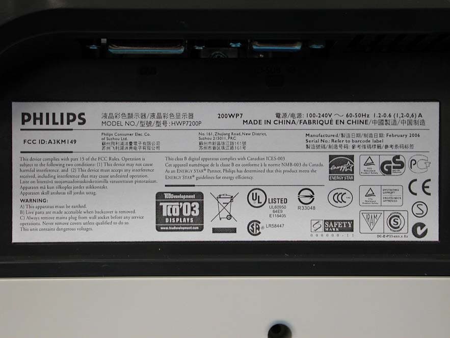
A3KM149
Mar 16, 200620� LCD Monitor
Equipment Class
JBP - Part 15 Class B Computing Device Peripheral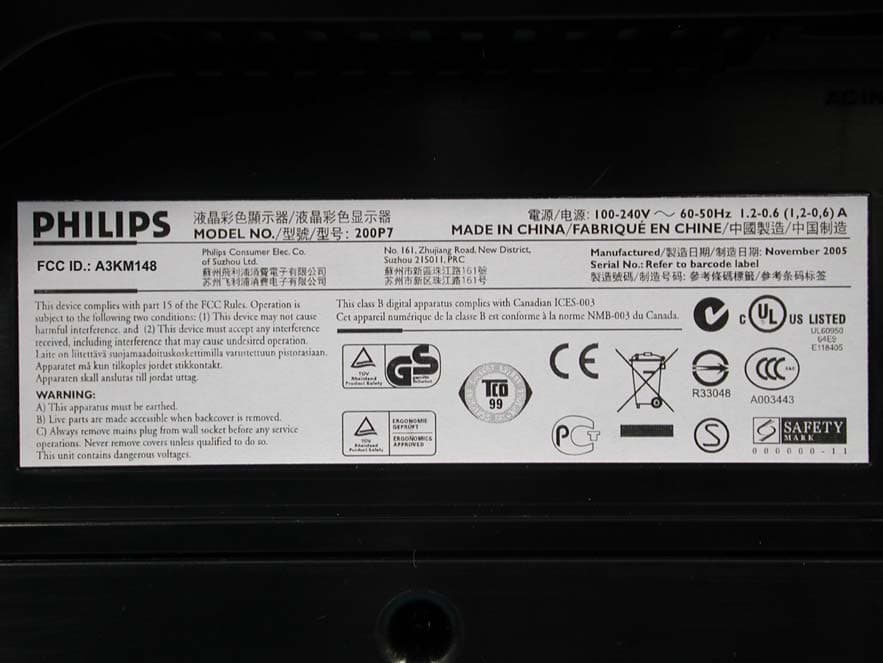
A3KM148
Dec 15, 200520
Equipment Class
JBP - Part 15 Class B Computing Device Peripheral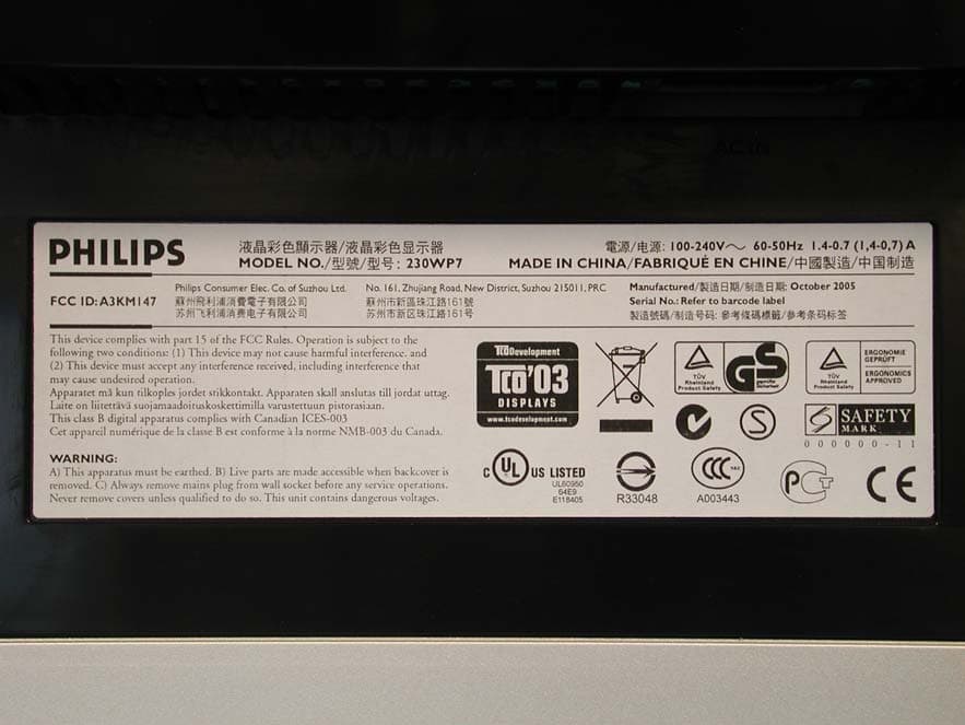
A3KM147
Nov 17, 2005LCD Monitor
Equipment Class
JBP - Part 15 Class B Computing Device Peripheral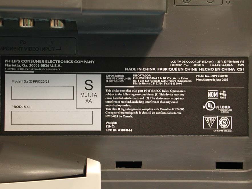
A3KM144
Jul 19, 2005LCD TV
Equipment Class
JBP - Part 15 Class B Computing Device Peripheral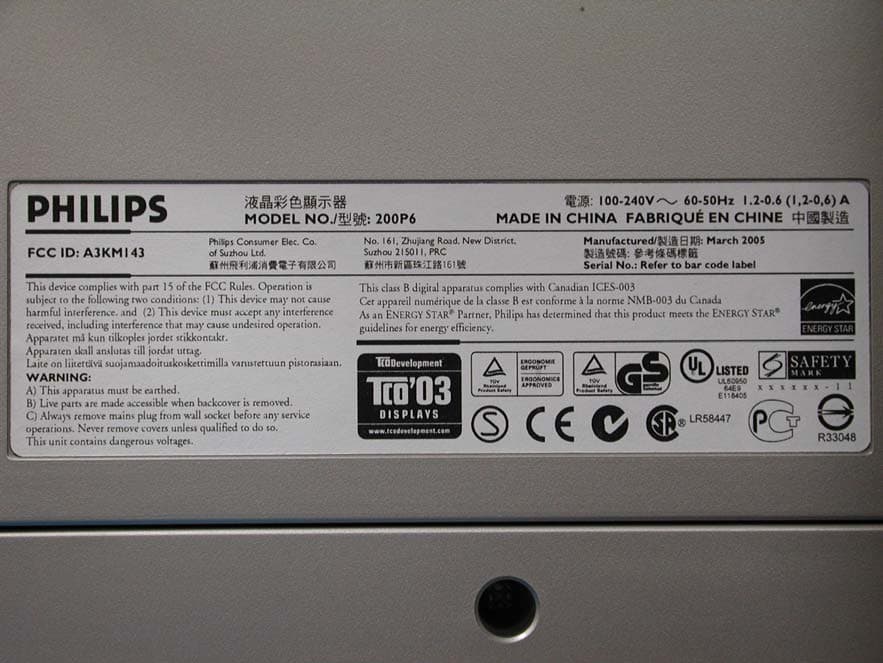
A3KM143
Apr 18, 2005Display Color Monitor
Equipment Class
JBP - Part 15 Class B Computing Device Peripheral