A3KM13023" TFT LCD/TV Monitor
Philips Electronics Industries (Taiwan) Ltd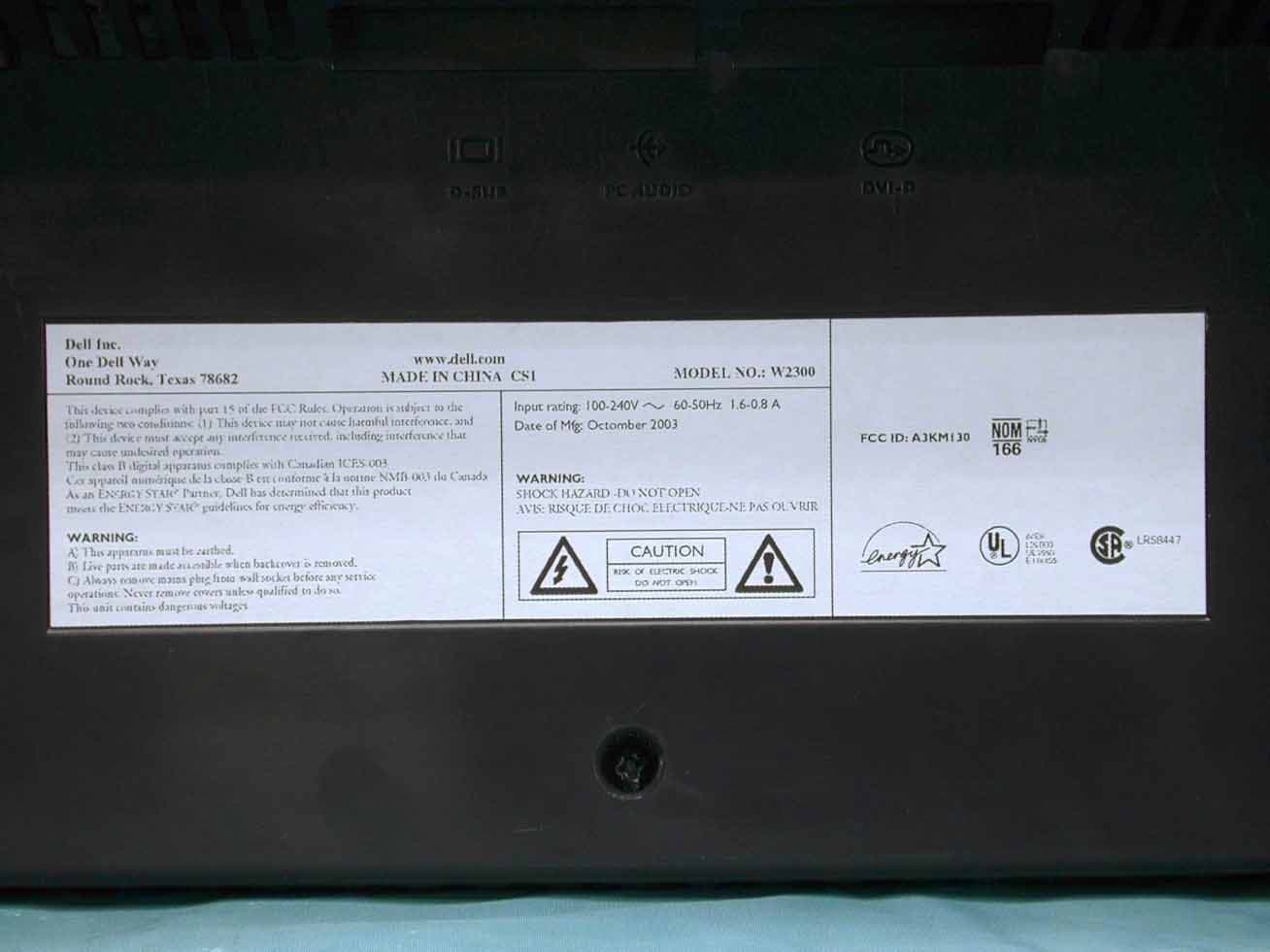
Click to zoom
Application Details
- Equipment Class
- JBP - Part 15 Class B Computing Device Peripheral
- Date of Grant
- Nov 23, 2003
- Application Purpose
- Original Equipment
- Date of Application
- Nov 23, 2003
- Equipment Note
- 23" TFT LCD/TV Monitor
- Country
- Taiwan
Documents & Files
Document Text
Text extracted from the exhibit documents filed with the FCC. Open a document above to read the original.
Users Manual
Specifications: Dell™ W2300 LCD TV User's Guide General • Flat Panel • Resolution • PC Display Modes • TV Display Modes • HDTV Display Modes • SDTV • Electrical • Physical Characteristics • Environmental • Power Management Modes • TV and Video Power Management Modes • Pin Assignments • Plug and Play Capability General Model numberW2300 LCD TV Flat Panel Screen dimensions Screen typeActive matrix - TFT LCD Screen dimensions23 inches (23-inch viewable image size) Preset display area: Horizontal 501.12± 3 mm (20.04 inches ± 0.12 inches) Vertical 300.67± 3 mm (12.03 inches ± 0.12 inches) Pixel pitch0.3915 mm Viewing angle+/- 88° (vertical) typ, +/- 88° (horizontal) typ Luminance output450 CD/m ²(typ) Contrast ratio400 to 1 (typ) Faceplate coatingAnti-glare BacklightCCFL (12) Panel Weight2.7 Kg/ 5.95lbs Resolution Horizontal scan range30 kHz to 61kHz (automatic) Vertical scan range56 Hz to 75 Hz (automatic) Optimal preset resolution1280 x 768 at 60 Hz Highest preset resolution1280 x 768 at 75 Hz * Highest addressable resolution1280 x 768 at 60 Hz * Addressable means the LCD TV will sync up to this mode. However, Dell does not guarantee the image will be sized, shaped and centered correctly. PC Display Modes Display ModeHorizontal Frequency (kHz) Vertical Frequency (Hz) Pixel Clock (MHz) Sync Polarity (Horizontal/Vertical) VGA, 720x 40031.46970.08728.3-/+ VGA, 640x 48031.46959.94025.2-/- Exhibit 3 Installstion and Operating Instructions TV Display Modes Americas model HDTV Display Modes SDTV VESA, 640 x 48037.50075.00031.5-/- VESA, 800 x 60037.87960.31740.0+/+ VESA, 800 x 60046.87575.00049.5+/+ VESA, 1024 x 76848.36360.00465.0-/- VESA, 1024 x 76860.02375.02978.8+/+ VESA, 1280 x 76847.77659.87079.5-/+ VESA, 1280 x 76860.28974.893102.25-/+ VESA, 1280 x 76847.39659.99568.25+/- Band Assignment AIR CHCATV CH CHVideo Carrier (MHz)CH Video Carrier (MHz) STD VHF LOW02-0655.25-83.2502-1555.25-127.25 VHF HIGH07-13175.25-211.2516-44133.25-343.25 UHF14-69471.25-801.2545-125349.25-799.25 Display ModeHorizontal Frequency (kHz) Vertical Frequency (Hz) Pixel Clock (MHz) Scan 1920 X 1080i 33.756074.25Interlace 1280 X 720P 456074.25Progressive 1920 X 1080i28.1255074.25Interlace 1280 X 720P37.55074.25Progressive CharacteristicsPALNTSCM Lines per picture625 frames525 frames Field frequency, nominal value60 fields/s59.94 fields/s Nominal video bandwidth5HMz4.2 MHz Norminal line period64μs63.5555μs Line-blanking interval12±0.3μs10.9±0.2μs Interval between time datum (0 H ) and back edge of line- blanking pulse 10.5μs9.2 to 10.3 μs Front porch1.5±0.3μs1.27 to 2.22μs Synchronizing pulse4.7±0.2μs4.7±0.1μs Build-up time of the line blacking pulse0.3±0.1μs=/< 0.48μs Build-up time of the line synchronizing pulse0.2±0.1μs=/< 0.25μs Start of sub-carrier burst5.6±0.1μs5.3(4.71 to 5.71)μs Duration of sub-carrier burst 2.25±0.23 (10±1 cycles)μs 2.23±3.11 (9±1 cycles)μs Electrical for PC Video input signalsAnalog RGB, 0.7 Volts +/-5%, positive polarity at 75 ohm input impedance Digital DVI-D TMDS, 600mV for each differential line, positive polarity at 50 ohm input impedance Synchronization input signalsSeparate horizontal and vertical synchronizations, polarity-free TTL level, Composite AC input voltage / frequency90 to 264 VAC / 50 or 60 Hz + 2Hz Physical Characteristics Connector type15-pin D-subminiature, blue connector; DVI-D, white connector Signal cable typeAnalog: Detachable, D-sub, 15pin, shipped detached to the LCD TV Digital: Detachable, DVI-D, Solid pins, shipped detached from the LCD TV Dimensions: (without packing) Height 448.0 mm (17.63 inches) Width 758.0 mm (29.84 inches) Depth 265.5 mm (10.45 inches) Weight (LCD TV only)13.8 Kg (30.4 lbs) Weight (with packaging)18.7 Kg (41.21 lbs) Environmental Temperature: Operating 0°C to 35°C (32°F to 95°F) Nonoperating Storage: 0 to 60°C (32°F to 140°F) Shipping: -20 to 60°C(-4°F to 140°F) Humidity: Operating 10% to 80% (noncondensing) Nonoperating Storage: 5% to 90% (noncondensing) Shipping: 5% to 90%(noncondensing) Altitude: Power Management Modes If you have VESA's DPMS compliance display card or software installed in your PC, the LCD TV can automatically reduce its power consumption when not in use. This is referred to as 'Power Save Mode'*. If input from keyboard, mouse or other input devices is detected by the computer, the LCD TV will automatically "wake up". The following table shows the power consumption and signaling of this automatic power saving feature: PC display power management mode TV and Video Power Management Modes * Zero power consumption in OFF mode can only be achieved by disconnecting the main cable from the monitor. E NERGY S TAR ® is a U.S. registered mark. As an E NERGY S TAR ® Partner, DELL has determined that this product meets the E NERGY S TAR ® guidelines for energy efficiency. Operating 3,657.6m (12,000 ft) max Nonoperating 12,192 m (40,000 ft) max Thermal dissipation239BTU/hour (typical at PC model) 342 BTU/hour (typical at TV model)) Power Management Definition VESA ModesVideoH-syncV-syncPower UsedLED color ONActive YesYes70W (typical)Green OFFBlanked NoNo< 3 WAmber NOTE: In Power Saving Mode, Press Any Key on Keyboard or Move Mouse. Activate the computer and 'wake up' the LCD TV to gain access to the OSD . Power management Definition DisplayVideoPower StatePower Used LED color ONActive Always On100W (typical) Green Stand byBlankedOff after 30minutes of no signal < 3WAmber Power switch offActive/BlankedOff< 1WOFF This monitor is E NERGY S TAR ®-compliant as well as TCO '99 power management Pin Assignments 15-pin D-Sub connector: 24 pin digital-only DVI cable: NOTE: This LCD TV automatically returns to normal operation when horizontal and vertical sync return, which occurs when you move the computer's mouse or press a key on the keyboard. Pin NumberLCD TV Side of the 15-Pin Side Signal Cable 1Red 2Green 3Blue 4GND 5Self test 6Red GND 7Green GND 8Blue GND 9+5V (supply form PC) 10Sync GND 11GND 12Bi-directional data (SDA) 13H. Sync 14V. Sync …
Text truncated - open the document above for the full version.
Block Diagram
Circuitry Description TV Box Tuner convert RF signal to CVBS and 2 nd IF, the CVBS is given to video decoder SAA7118 and 2 nd IF is given to audio decoder MSP34X0G. video/audio connecters (YPbPr & SVHS & AV input & AV output ) except PC audio are placed in this box, YPbPr own its audio input , SVHS and AV input share one audio input. The video signals are given to video decoder SAA7118 in main board and the audio Signals are given to audio decoder MSP34X0G via s multiplex. The output of MSP34x0G is sent to audio amplifier TPA3004D2 . All the sound effect ,volume/bass/treble/delta/etc , are made by MSP34x0G. This board connects to Main board with 30 pins connector . Audio Board Audio amp TPA3004D2 is used, it provide 10Wx2 audio power to speaker box , the earphone and line out jack are put at the edge of the board, speaker will be mute when earphone or line out is plugged in ,this board is connected to main BD with 10 pins connector. Key Control Board 6 push keys & power switch & infrared receiver are here, the keys signals and IR signal are sent to Painter I (uP) for decoding. the power switch is to control the Vcc of the painter I uP Exhibit 3 Brief Description of Circuit Functions Main Board Video Video decoder SAA7118 convert analog video signal to 656/8 bit to video converter FLI2300 , the FLI2300 provide the function of video de-interlacing , LTI & CTI, noise reduction, color suppression with 2D comb filter , true color enhancement and film 3:2/2:2 pull down, it is scaling the video to 1280x768 output, FLI2300 need a extra SDRAM for the memory of de- interlacing HD YPbPr input The TDA9883 convert analog HD signal YPbPr input to 24 bits digital output , then send this 24 bits data to FLI2300 , and the sync out from TDA9883 will be given to scaler JagASM for mode detection , the YPbPr is also sent to SAA7118 for decoding , the uP will know what kind of video is inputted. TDA9883 will be working for progressive YPbPr and SAA7118 will be working for interlace YPbPr. PC graphic & DVI 135MHz ADC had built inside the JagASM scaler, so PC signal directly sent to JagASM analog port ,It scales all modes to 1280x768 output. The Sil151 will convert PC DVI digital input to 24 bit then send to digital port of JagASM scaler. It scales all modes to 1280x768 output There are two DDC EEPROM ,one for analog PC D-sub input, the other one is for PC DVI digital input. PIP The JagASM need 32 bit SDRAM to memory the video signal when PIP mode is enabled, the down Scaled video is made by FLI2300 and mix the video into PC graphic and PC DVI Digital in JagASM. OSD The OSD is created in JagASM scaler and mixed in JagASM. uP There are 2 uPs are designed in Painter It provide TxT & CC & V Chip library, and it also used for power saving detection and user key detection. It control the video decoder SAA7118 & Audio decoder MSP34X0G & Tuner via IIC MX10E8050 It is responsible for the scaling part & HDTV part ,it control scaler JagASM & AD9883 via IIC, and it control the scaler JagASM via the memory mapping method. The two uPs is communicated each other via a independent IIC Power Internal power board is used , supply 24VDC for Inverter and 16VDC for scaler board power and Audio amplifier, DC-DC converter are used to convert 16V to 12V for panel T-cone driver , and convert 16V to 5V/3.3V/2.5V/1.8V for chips and tuner ,a 3V3 switching power is used for painter uP for power saving purpose . Dell W2300 LCD TV-Monitor System Functional Block Inveter Power board Scaller board TV Board AC 110-220 VGA DVI-D SCART/ D4 +12V +24V Ant . Audio Amp. PC audio Control key board/ RC receiver/power LED/Power switch CVBS,YC,L/R audio YpbPr, L/R, audio L/R line out/ headphoneSpeakers Exhibit 5 Scaler board Functional Block Scaler Genesis JagASM WXGA Panel Video decoder SAA7118A 2 n d IF Sound decoder MSP34X0G Audio Power amp 10WX2 & earphone/ Line out TPDA3004D2 CPU (8050) + Flash Painter I .Teletext .C.C/V-chip Key pad IR Power sw SDRAM TV Box .Tuner .YPbPr cinch.S video .R/L cinch .Switch Video Converter FLI2300 SDRAM LVDS Tx ADC AD 9883A PC IN YPbPr- video&audio IN TMDS SiL151 DVI - D SDTV YPbPr HDTV YPbPr TNU-CVBS S-video/ AV video & audio IN A V - CV B S RF IN R/L for YPbPr R/L for S/AV PC aud io R/L audio H/V Sync DDCDDC Analog RGB 24 bits& CLK 24 bits &CLK 24 bit &CLK 8 bits &CLK RGBHV IIC MUX 4052 HV HV HV S Video R/L for SCART/D4 SCART/D4 Power board DC-to – DC Power 16V Inverter BD 24V
External Photos
Exhibit 7 Photographs Front View Rear View Label Assembly w/o Base
ID Label/Location Info
Exhibit 2 FCC ID Label
Internal Photos
Assembly w/o Back Cover Shielding Cover Assembly w/o Shielding Cover PCB Layout PCB Layout PCB Layout PCB Layout PCB Layout PCB Layout Plate LCD Panel Power Cord and I/F Cables
Test Report
Philips Electronics Industries (Taiwan) Ltd - EMC Lab. 5, Tze Chiang 1 Road, Chungli Industrial Park, Chungli, Taoyuan, Taiwan Tel.: +886-3-454-9862 Fax.: +886-3-454-9887 E-mail: [email protected] FCC Test Report Report No.: TYR87-2059 Date : 20 November, 2003 Page : Page 1 of 40 Customer : Philips Electronics Industries Name : Mr. S.T. Huang – EE LCD Address : 5, Tze Chiang 1 Road, Zip/City : Chungli Industrial Park, Country : Chungli, Taiwan, R.O.C. Equipment Under Test (including peripherals) : FCC ID. : A3KM130 Model Name : W2300 Serial Number : TY0304621 Description : 23” SXGA LCD TV monitor, Max. resolution 1280x768/75Hz EMC Standards : FCC Part 15 of October 01,1999 Class B ANSI C63.4-1992 Result : PASSED the limits/test-levels in the standards. Note : The results in this report apply only to the sample(s) and mode(s) tested. It is the manufacturer’s responsibility to assume the continued EMC compliance of production models. Date of receipt of EUT : 07 Nov. 2003 Date of performance of test : 08 Nov., 2003 to 11 Nov., 2003 Philips Electronics Industries (Taiwan) Ltd This report shall not be reproduce except in full, without written approval of the testing laboratory C.C. Wu - EMC Test Engineer Ronnie Yang - EMC Manager Reference: TYR87-2059 W2300 Date: 20 November 2003 Philips Electronics Industries (Taiwan) Ltd Page: 2 of 40 Table of contents 1. Summary of test results.............................................................................3 2. General information of EUT.......................................................................4 3. Test equipment.......................................................................................5 4. Test configuration of EUT and peripherals......................................................6 5. Test procedure.......................................................................................7 6. Measurement uncertainty...........................................................................9 7. Conducted emissions test..........................................................................10 8. Radiated emissions test............................................................................23 9. Photographs of test set-up.........................................................................36 10. References...........................................................................................40 Reference: TYR87-2059 W2300 Date: 20 November 2003 Philips Electronics Industries (Taiwan) Ltd Page: 3 of 40 1. Summary of test results Test Standard Result Note Emission, ANSI C63.4-1992 Conducted emission Radiated emission FCC Part 15 FCC Part 15 Passed Passed Remark: The test sample fully complies with the requirements set forth in : FCC Part 15 Class B. Reference: TYR87-2059 W2300 Date: 20 November 2003 Philips Electronics Industries (Taiwan) Ltd Page: 4 of 40 2. General Information of EUT The EUT, 23” color monitor : Model No. : W2300 FCC ID : A3KM130 Brand : DELL The color monitor automatically scans horizontal frequencies between 30KHz and 61KHz , and vertical frequencies between 56Hz and 75Hz. This color monitor displays sharp and brilliant images of text and graphics with a maximum resolution up to 1280x768 pixels. The monitor has 10 factory-preset modes as indicated in the following table: Mode Resolution H. freq. / V. freq Standard 1. 720 x 400 31.469Khz/70.087Hz VGA 2. 640 x 480 31.469Khz/59.940Hz VGA 3. 640 x 480 37.500Khz/75.000Hz VESA 4. 800 x 600 37.879Khz/60.317Hz VESA 5. 800 x 600 46.875Khz/75.000Hz VESA 6. 1024 x 768 48.363Khz/60.004Hz VESA 7. 1024 x 768 60.023Khz/75.029Hz VESA 8. 1280 x 768 47.776Khz/59.87Hz CVT 9. 1280 x 768 60.289Khz/74.893Hz CVT 10. 1280 x 768 47.396Khz/59.995Hz CVT-R Reference: TYR87-2059 W2300 Date: 20 November 2003 Philips Electronics Industries (Taiwan) Ltd Page: 5 of 40 3. Test Equipment Test equipment used for line Conducted and Radiated emissions as following. All equipment were calibrated according to ANSI C63.4-1992 and ISO-9000 requirement unless otherwise specified. Traceability to R.O.C. and international standards is assured by using calibrated all equipment. - For Conducted Emissions Test: Test Equipment Model No. Serial No. Last Calibrate Next Calibrate Spectrum HP8568B 2928A04640 02/27/2003 02/27/2004 EMI Receiver R & S ESVS30 841977/006 02/27/2003 02/27/2004 LISN EMCO 3825/2 9311-2153 06/16/2003 06/16/2004 LISN EMCO 3825/2 9311-2154 06/16/2003 06/16/2004 RF Cable 8-meter N/A 08/21/2003 08/21/2004 - For Radiated Emissions Test: Test Equipment Model No. Serial No. Last Calibrate Next Calibrate Spectrum HP8568B 2928A04640 09/23/2003 09/23/2004 RF Preselector HP85685A 2620A00338 09/23/2003 09/23/2004 QP Adapter HP85650A 2811A01324 09/23/2003 09/23/2004 EMI Receiver R & S ESVS30 841977/006 02/27/2003 02/27/2004 Biconical Antenna EMCO 3110B 3224 08/21/2003 08/21/2004 Log-Periodic Antenna EMCO 3146A 1425 08/21/2003 08/21/2004 Turn Table EMCO 1060 1068 08/21/2003 08/21/2004 Antenna Tower EMCO 1050 1113 08/21/2003 08/21/2004 RF Cable M17/75-RG214-NE N/A 08/21/2003 08/21/2004 Reference: TYR87-2059 W2300 Date: 20 November 2003 Philips Electronics Industries (Taiwan) Ltd Page: 6 of 40 4. Test Configuration of EUT and Peripherals The system was configured for testing in a typical fashion ( as a customer would normally use it ) according to ANSI C63.4-1992, please see the photographs for detail. For system measurement, the EUT “W2300” were connected to: Description Brand/ Model No. Serial No. FCC ID Remark A Monitor DELL W2300 TY0304621 A3KM130 EUT B PC DELL DHM FK25Y21 FCC Logo C Keyboard DELL SK-8100 38844-193-7480 FCC Logo D Mouse DELL M-S69 LZA31578847 JNZ211443 E Modem Hayes 231AA A22231081770 BFJ9D9308US F Printer HP 2225C 2934S55406 DSI6XU2225 Connected Cables No. Description Manufacturer Length Shielded Remark 1 Power Cord Long Shine 1.8 meters No for EUT 2 Power Cord Acer 1.8 meters No for PC 3 Power Cord Aceex 2.0 meters No for Modem 4 Power Cord HP 1.8 meters …
Text truncated - open the document above for the full version.
Test Setup Photos
Reference: TYR87-2059 W2300 Date: 20 November 2003 Philips Electronics Industries (Taiwan) Ltd Page: 36 of 40 9. Photographs of Test Set-up Conducted Emissions Test Reference: TYR87-2059 W2300 Date: 20 November 2003 Philips Electronics Industries (Taiwan) Ltd Page: 37 of 40 Conducted Emissions Test Reference: TYR87-2059 W2300 Date: 20 November 2003 Philips Electronics Industries (Taiwan) Ltd Page: 38 of 40 Radiated Emissions Test Reference: TYR87-2059 W2300 Date: 20 November 2003 Philips Electronics Industries (Taiwan) Ltd Page: 39 of 40 Radiated Emissions Test Reference: TYR87-2059 W2300 Date: 20 November 2003 Philips Electronics Industries (Taiwan) Ltd Page: 40 of 40 10. Reference FCC part 15 - 1999 Radio frequency device. ANSI C63.4-1992, “American national standard for measurement of radio-noise emission from low-voltage electrical and electronic equipment in the range of 9KHz to 40GHz”
Contact Information
Applicant
Ronnie Yang(Manager, Safety/DEV)
Test Firm
Philips Electronics Industries (Taiwan) Ltd.Ronnie Yang
Technical Specifications
| # | Rule Parts | Frequency Range | Power Output |
|---|---|---|---|
| 1 | 15B | - | - |
Other Applications from Philips Electronics Industries (Taiwan) Ltd
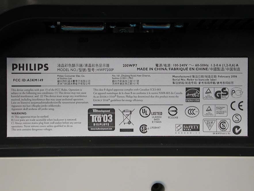
A3KM149
Mar 16, 200620� LCD Monitor
Equipment Class
JBP - Part 15 Class B Computing Device Peripheral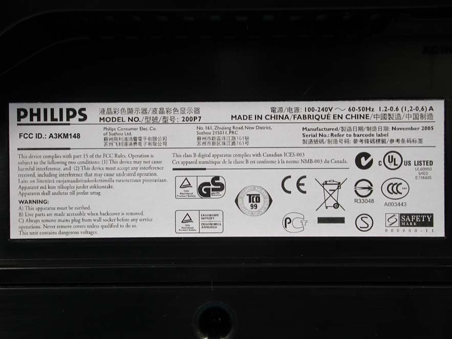
A3KM148
Dec 15, 200520
Equipment Class
JBP - Part 15 Class B Computing Device Peripheral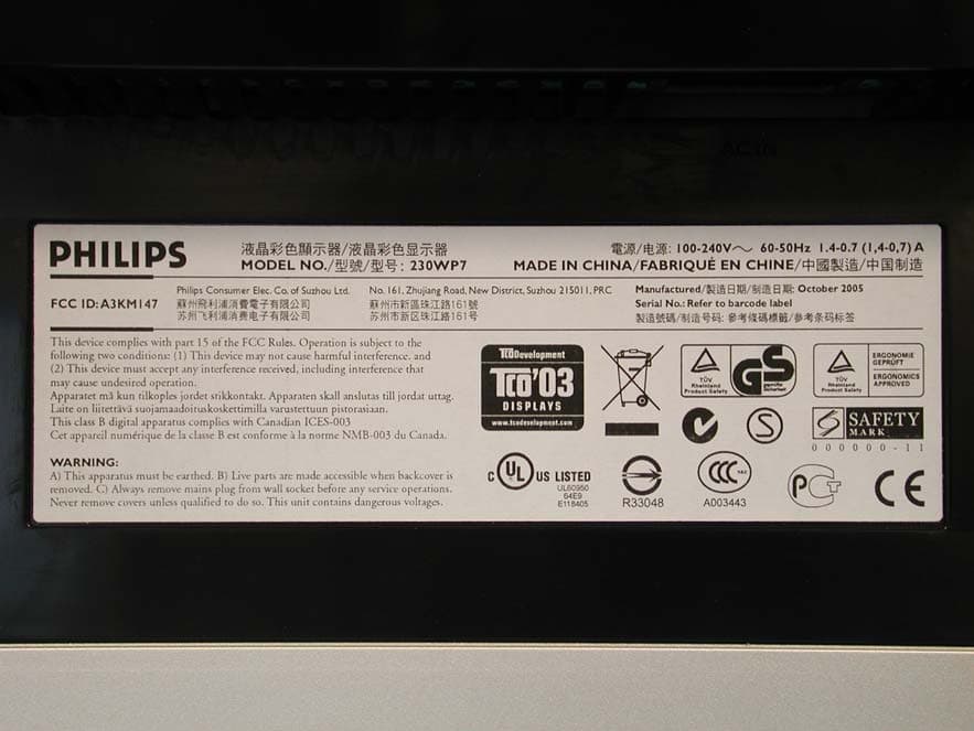
A3KM147
Nov 17, 2005LCD Monitor
Equipment Class
JBP - Part 15 Class B Computing Device Peripheral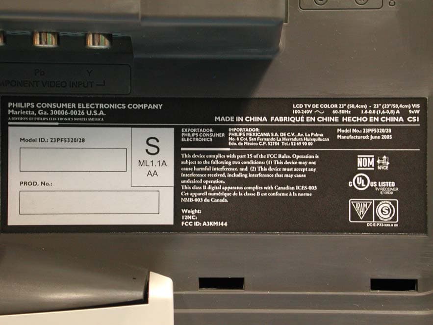
A3KM144
Jul 19, 2005LCD TV
Equipment Class
JBP - Part 15 Class B Computing Device Peripheral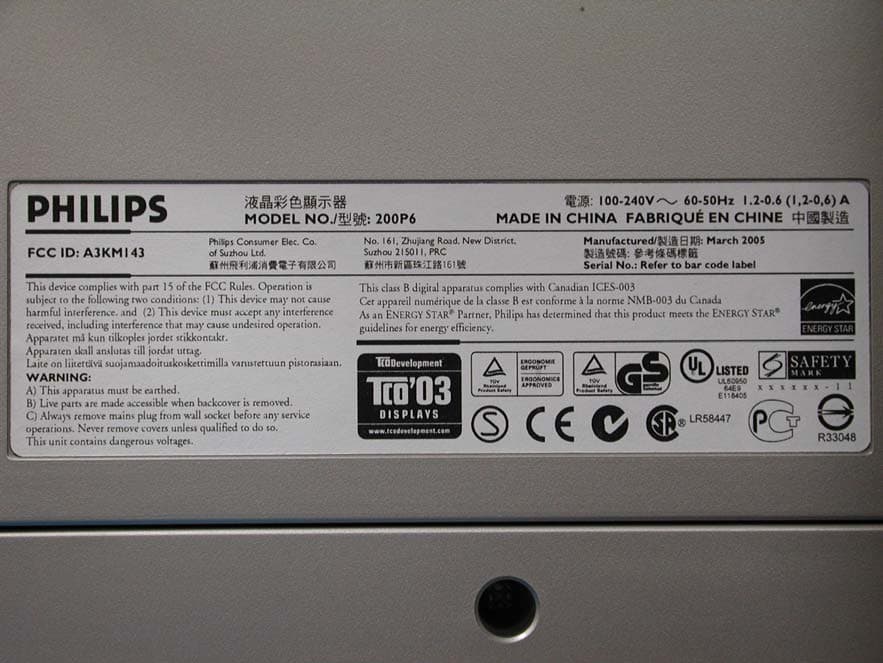
A3KM143
Apr 18, 2005Display Color Monitor
Equipment Class
JBP - Part 15 Class B Computing Device Peripheral