A3KM131LCD / TV Monitor
Philips Electronics Industries (Taiwan) Ltd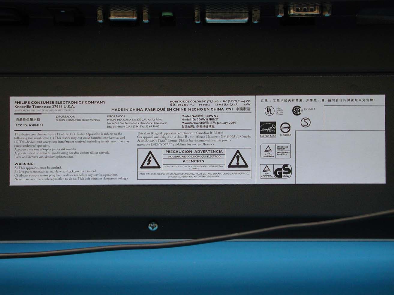
Click to zoom
Application Details
- Equipment Class
- JBP - Part 15 Class B Computing Device Peripheral
- Date of Grant
- Mar 11, 2004
- Application Purpose
- Original Equipment
- Date of Application
- Mar 11, 2004
- Equipment Note
- LCD / TV Monitor
- Country
- Taiwan
Documents & Files
Document Text
Text extracted from the exhibit documents filed with the FCC. Open a document above to read the original.
Users Manual
Product Information Product Features • Technical Specifications • Resolution & Preset Modes • Philips Pixel Defect Policy • Automatic Power Saving • Physical Specification • Pin Assignment • Product Views Product Features 300WN5 z29.5-inch WXGA (1280x768 resolution, 176 degree viewing angle) LCD all-in-one Monitor TV with excellent display performance zMultiple video input allowing display of PC, TV, HDTV, VCD, DVD, Progressive DVD and Camcorder zNetwork controllability via RS232 interface for managing the performances, setting, etc. zDigital High Definition Picture (1080i, 720p, 576p, 576i, 480p, 480i) zDCDi TM de-interlacinf technology for superior depiction of motion zPicture-in-Picture (PIP) function in PC VGA mode zLight sensor to adjust brightness automatically zTeletext (available only in Asia Pacific and Western Europe) zDigital Nicam/2CS stereo (available only in Asia Pacific and Western Europe) zComponent Video Input (YPbPr/YCbCr) for DVD (available in AV and TV models only) zEuroconnector (SCART) (available in Western Europe) zMultiSystem TV tuner-PAL/NTSC (available in TV model only) RETURN TO TOP OF THE PAGE Technical Specifications* LCD PANEL • TypeTFT LCD • Screen size29.5 inch • Pixel Pitch0.5025 x 0.1675 mm x RGB • LCD Panel type 1280 x 768 pixels R.G.B. vertical stripe Hard coating surface, anti-glare polarizer • Effective viewing area(H) 643.2 x (V) 385.92mm • Display Colors8 bits interface (16.7M colors) PC SCANNING • Vertical refresh rate 58Hz-60Hz • Horizontal frequency 31kHz-49kHz PC VIDEO • Video dot rate< 80 MHz • Input impedance Installstion and Operating Instructions Exhibit 3 - Video 75 ohm - Sync 2.2K ohm • Input signal levels0.7 Vpp • Sync input signal Separate sync • Sync polaritiesPositive and negative • Input Frequency WXGA Hsync 48 kHz, Vsync 60 Hz (N.I.) SVGA Hsync 38 kHz, Vsync 60 Hz (N.I.) VGA Hsync 31 kHz, Vsync 60 Hz (N.I.) • Video interface D-sub, S-Video, TV-RF, SCART (Europe) or composite and components video (others) AUDIO • Input level for PC/SVHS/SCART 500 mV nominal • Loudspeaker 5W Stereo Audio (2.5W/channel RMS x2, 200Hz~10kHz, 4 ohm, 10% THD) OPTICAL CHARACTERISTICS • Contrast ratio 500:1 (typ.) • Brightness 500 cd/m 2 (typ.) • Peak contrast angle6 o'clock • White Chromaticity x: 0.283 y: 0.297 (at 9300°K) x: 0.313 y: 0.329 (at 6500°K) x: 0.328 y: 0.344 (at 5700°K) • Viewing Angle (C/R >5) Upper >88° (typ.) Lower > 88° (typ.) Left >88° (typ.) Right >88° (typ.) • Response time <=16ms (typ.) sRGB sRGB is a standard for ensuring correct exchange of colors between different devices (e.g. digital cameras, monitors, printers, scanners, etc.) Using a standard unified color space, sRGB will help represent pictures taken by an sRGB compatible device correctly on your sRGB enabled Philips monitors. In that way, the colors are calibrated and you can rely on the correctness of the colors shown on your screen. Important with the use of sRGB is that the brightness and contrast of your monitor is fixed to a predefined setting as well as the color gamut. Therefore it is important to select the sRGB setting in the monitor's OSD. To do so, at PC mode, open the OSD by pressing the MENU button of your monitor. Use the down button to go to COLOR SETTINGS and press MENU again. Then move the down * This data is subject to change without notice. RETURN TO TOP OF THE PAGE Resolution & Preset Modes RETURN TO TOP OF THE PAGE Automatic Power Saving If you have VESA DPMS compliance display card or software installed in your PC, the monitor can automatically reduce its power consumption when not in use. If an input from a keyboard, mouse or other input device is detected, the monitor will then 'wake up' automatically. The following table shows the power consumption and signaling of this automatic power saving feature: button to go to NORMAL COLOR and press MENU again. For more information on sRGB, please visit: www.srgb.com • Recommended 1280 x 768 at 60Hz 10 factory preset modes: Resolution Mode H. freq (kHz) V. freq (Hz) PC 640*480 VGA VESA 60 31.469 59.940 800*600 SVGA VESA 60 37.879 60.317 1024*768 XGA VESA 60 48.363 60.004 1280*768 GTF 60 47.700 60.000 Video EDTV 480P 31.470 60.000 SDTV 480i 15.734 59.940 EDTV 576P 31.250 50.000 SDTV 576i 15.625 50.000 HDTV 1080i 33.750 60.000 HDTV 720P 45.000 60.000 Power Management Definition Power LED RETURN TO TOP OF THE PAGE Physical Specifications * This data is subject to change without notice. RETURN TO TOP OF THE PAGE Pin Assignment 1. The digital only connector contains 24 signal contacts organized in three rows of eigh contacts. Signal pin assignments are listed in the following table: VESA Mode Video H-sync V-sync Used color ON Active Pulse Pulse 130W (typ.) Blue OFF Blanked NoNo< 5WAmber AC OFF Blanked No No < 2W Off This monitor is ENERGY STAR ® compliant. As an ENERGY STAR ® Partner, PHILIPS has determined that this product meets the E NERGY S TAR ® guidelines for energy efficiency. • Dimension (WxHxD) * 867.7mm x 505mm x 183mm (incl. Pedestal, Speakers) 726.7mm x 469.3mm x 115mm (w/o Pedestal, Speakers) • Weight 16.0 kg (incl. Pedestal, Speakers) 14.0 kg (w/o Pedestal, Speakers) 15.0 kg (w/o Pedestal, Speakers; with protective cover) • Power supply90 — 264 VAC, 50/60 Hz • Power consumption PC Mode: 130 W (typ.) TV Mode: 150 W (typ.) • Temperature (operating)0° C to 35° C • Relative humidity 20% to 80% • System MTBF 50K hrs (excluding CCFL 40Khrs) Pin No. Signal Assignment Pin No. Signal Assignment Pin No. Signal Assignment 1 T.M.D.S. Data2- 9 T.M.D.S. Data1-17T.M.D.S. Data0- 2 T.M.D.S. Data2+ 10 T.M.D.S. Data1+18T.M.D.S. Data0+ 3 T.M.D.S. Data2/4 11 T.M.D.S. Data1/3 19 T.M.D.S. Data0/5 2. The 15-pin D-sub connector (male) of the signal cable: 3. RS232 Connector D-sub 9-pin male connector for communication with plasma engine or PC. Shield Shield Shield 4 No connect 12 No connect 20No connect 5 No connect 13 No connect 21No connect 6 DDC Clock 14 +5V Power 22 T.M.D.S. Clock Shield 7 DDC Data 15 Hot Plug Detect23T.M.D…
Text truncated - open the document above for the full version.
Block Diagram
Circuitry Description TV Board Tuner convert RF signal to CVBS and 2 nd IF, the CVBS is given to video decoder SAA7118 and 2 nd IF is given to audio decoder MSP34X0G. video/audio connecters (SCART & YPbPr & SVHS & AV input & AV output ) except PC audio are placed in this board, YPbPr own its audio input , SVHS and AV input share one audio input. SCART and YPbPr have a multiplexer circuit to switch their signals. The video signals are given to video decoder SAA7118 in main board and the audio Signals are given to audio decoder MSP34X0G vias multiplexer. The output of MSP34x0G is sent to audio amplifier TDA1517 . All the sound effect ,volume/bass/treble/delta/etc , are made by MSP34x0G. This board connects to Main board with 30 pins connector . Audio Board Audio amp TDA1517 is used, it provide 5Wx2 audio power to Audio out jack board for the connection of two external speaker boxes. Audio out jack Board There are three output jacks on the board. The upper two jacks are for L and R external speakers. The lowest one is for Line Out. Speakers will be mute when line out jack is plugged in. This board is connected to Audio Board with a 10 pins connector. Brief Description of Circuit Functions Exhibit 4 Key Control Board 6 push keys & DC power switch are here, the keys signals are sent to Painter I (uP) for decoding. The DC power switch is to control the Vcc of the painter I uP IR Board There are infrared receiver, Light sensor and Power LED on the board. The Light sensor signal and IR signal are sent to Painter I (uP) for decoding. The Power LED is controlled by painter I (uP) to show the power supply’s status. Main Board Video Video decoder SAA7118 convert analog video signal to 656/8 bit to video converter FLI2300 , the FLI2300 provide the function of video de-interlacing , LTI & CTI, noise reduction, color suppression with 2D comb filter , true color enhancement and film 3:2/2:2 pull down, it is scaling the video to 1280x768 output, FLI2300 need a extra SDRAM for the memory of de- interlacing HD YPbPr input The TDA9883 convert analog HD signal YPbPr input to 24 bits digital output , then send this 24 bits data to FLI2300 , and the sync out from TDA9883 will be given to scaler JagASM for mode detection , the YPbPr is also sent to SAA7118 for decoding , the uP will know what kind of video is inputted. TDA9883 will be working for progressive YPbPr and SAA7118 will be working for interlace YPbPr. PC graphic & DVI 135MHz ADC had built inside the JagASM scaler, so PC signal directly sent to JagASM analog port ,It scales all modes to 1280x768 output. The Sil151 will convert PC DVI digital input to 24 bit then send to digital port of JagASM scaler. It scales all modes to 1280x768 output There are two DDC EEPROM ,one for analog PC D-sub input, the other one is for PC DVI digital input. PIP The JagASM need 32 bit SDRAM to memorize the video signal when PIP mode is enabled, the down Scaled video is made by FLI2300 and mix the video into PC graphic and PC DVI Digital in JagASM. OSD The OSD is created in JagASM scaler and mixed in JagASM. uP There are 2 uPs are designed in : Painter and MX10E8050. Painter It provide TxT & CC & V Chip library, and it also used for power saving detection and user key detection. It control the video decoder SAA7118 & Audio decoder MSP34X0G & Tuner via IIC MX10E8050 It is responsible for the scaling part & HDTV part ,it control scaler JagASM & AD9883 via IIC, and it control the scaler JagASM via the memory mapping method. The two uPs is communicated each other via a independent IIC Power Internal power board is used , supply 24VDC for Inverter and 16VDC for scaler board power and Audio amplifier, DC-DC converter are used to convert 16V to 12V for panel T-cone driver , and convert 16V to 5V/3.3V/2.5V/1.8V for chips and tuner ,a 3V3 switching power is used for painter uP for power saving purpose . 300WN5 LCD Multifunction Monitor (TV model) System Functional Block Inveter Power board Scaler board TV Board AC 110-220 VGA DVI-D SCART (for WE model only) +16V +24V RF in Audio Amp. PC audio Control key board/ Power switch RS232 CVBS,YC,audio L/R, YpbPr, audio L/R line out L/R Speakers Light Sensor/RC receiver/power LED LVDS interface To LCD Panel To LCD Panel CVBS, audio L/R output Exhibit 5 Block Diagram
External Photos
Exhibit 7 Photographs Front View Rear View Label
ID Label/Location Info
Exhibit 2 FCC ID Label
Internal Photos
Assembly w/o Front Cabinet Assembly w/o Back Cover PCB Layout PCB Layout PCB Layout PCB Layout PCB Layout PCB Layout Assembly w/o PCB Plate LCD Panel Power Cord and I/F Cables
Test Report
FCC ID. A3KM131 Page 1 of 47 Audix Corporation. Report No. EM-F930007 APPLICATION FOR CERTIFICATION On Behalf of Philips Electronics Industries (Taiwan) Ltd. Flat Panel Color Monitor Model No.:300WN5 Brand : Philips FCC ID: A3KM131 Prepared for : Philips Electronics Industries (Taiwan) Ltd. 5, Tze Chiang 1 Rd, Chungli Ind. Park, Chungli, Taoyuan Hsien, Taiwan, R.O.C. Prepared By : AUDIX Corporation Technical Division EMC Department No. 53-11, Tin-Fu Tsun, Lin-Kou, Taipei Hsien, Taiwan, R.O.C. Tel: (02) 2609-9301, 2609-2133 Fax: (02) 2609-9303 File Number : EM930007 Report Number : EM-F930007 Date of Test : Jan. 07 ~ 12, 2004 Date of Report : Jan. 14, 2004 FCC ID. A3KM131 Page 2 of 47 Audix Corporation. Report No. EM-F930007 TABLE OF CONTENTS Description Page Test Report Certification........................................................................................................................3 1. GENERAL INFORMATION ...........................................................................................................4 1.1. Description of Device (EUT) .................................................................................................................... 4 1.2. Tested Supporting System Details ............................................................................................................ 5 1.3. Test Facility .............................................................................................................................................. 7 1.4. Measurement Uncertainty ......................................................................................................................... 7 2. CONDUCTED DISTURBANCE MEASUREMENT .....................................................................8 2.1. Test Equipment ......................................................................................................................................... 8 2.2. Block Diagram of Test Setup.................................................................................................................... 8 2.3. Powerline Conducted Emission Limit (Class B) ...................................................................................... 8 2.4. EUT’s Configuration during Compliance Measurement .......................................................................... 9 2.5. Operating Condition of EUT..................................................................................................................... 9 2.6. Test Procedure ........................................................................................................................................ 10 2.7. Test Results ............................................................................................................................................. 10 3. RADIATED DISTURBANCE MEASUREMENT .......................................................................25 3.1. Test Equipment ....................................................................................................................................... 25 3.2. Block Diagram of Test Setup.................................................................................................................. 25 3.3. Radiated Emission Limits (Class B) ....................................................................................................... 26 3.4. EUT’s Configuration during Compliance Measurement ........................................................................ 26 3.5. Operating Condition of EUT................................................................................................................... 26 3.6. Test Procedure ........................................................................................................................................ 27 3.7. Radiated Emission Measurement Results ............................................................................................... 28 4. DEVIATION TO TEST SPECIFICATIONS................................................................................42 5. PHOTOGRAPHS.............................................................................................................................43 5.1. Photos of Powerline Conducted Measurement .......................................................................................43 5.2. Photos of Radiated Measurement at Open Field Test Site...................................................................... 45 FCC ID. A3KM131 Page 3 of 47 Audix Corporation. Report No. EM-F930007 TEST REPORT CERTIFICATION Applicant : Philips Electronics Industries (Taiwan) Ltd. Manufacturer : Philips Electronics Industries (Taiwan) Ltd. EUT Description : Flat Panel Color Monitor FCC ID : A3KM131 (A) MODEL NO. : 300WN5 (B) SERIAL NO. : TY0304735 (C) BRAND NAME : Philips (D) POWER SUPPLY: AC 100-240V~ 60-50Hz (Test Voltage: AC 120V/60Hz) Measurement Standards and Methods Used : FCC CFR 47 Part15 / Dec. 2003 and ANSI C63.4-2001 The device described above was tested by AUDIX CORPORATION to determine the maximum emission levels emanating from the device. The maximum emission levels were compared to the Class B radiated emission limit against the §15.109(a) of FCC Part 15 and the conducted emission limit of §15.107(a) of FCC Part 15. The measurement results are contained in this test report and AUDIX CORPORATION is assumed full responsibility for the accuracy and completeness of these measurements. Also, this report shows that the EUT to be technically compliance with the FCC official limits. This report applies to above tested sample only. This report shall not be reproduced in part without written approval of Audix Corporation. Date of Test : Jan. 07 ~ 12, 2004 Prepared by : (Julie Hsu/Assistant Officer) Test Engineer : (Allen Wang/Deputy Manager) Approved & Authorized Signer : (Leon Liu/Assistant General Manager) Name of the Representative of the Responsible Party : Signature : FCC ID. A3KM131…
Text truncated - open the document above for the full version.
Test Setup Photos
FCC ID. A3KM131 Page 43 of 47 5. PHOTOGRAPHS 5.1. Photos of Powerline Conducted Measurement Display:VGA IN FRONT VIEW OF CONDUCTED TEST BACK VIEW OF CONDUCTED TEST Audix Corporation. Report No. EM-F930007 FCC ID. A3KM131 Page 44 of 47 Display :PIP FRONT VIEW OF CONDUCTED TEST BACK VIEW OF CONDUCTED TEST Audix Corporation. Report No. EM-F930007 FCC ID. A3KM131 Page 45 of 47 5.2. Photos of Radiated Measurement at Open Field Test Site Display:VGA IN FRONT VIEW OF RADIATED TEST BACK VIEW OF RADIATED TEST Audix Corporation. Report No. EM-F930007 FCC ID. A3KM131 Page 46 of 47 Display :PIP FRONT VIEW OF RADIATED TEST BACK VIEW OF RADIATED TEST Audix Corporation. Report No. EM-F930007 FCC ID. A3KM131 Page 47 of 47 Display :PIP (1280*768/60Hz, 48kHz, D-SUB Cable) SETUP WITH MAXIMUM DETECTED EMMISSION AT HORIZONTAL POLARIZATION SETUP WITH MAXIMUM DETECTED EMMISSION AT VERTICAL POLARIZATION Audix Corporation. Report No. EM-F930007
Contact Information
Applicant
Ronnie Yang(Manager, Safety/DEV)
Test Firm
Audix Technology CorporationJeff Chen
Technical Specifications
| # | Rule Parts | Frequency Range | Power Output |
|---|---|---|---|
| 1 | 15B | - | - |
Other Applications from Philips Electronics Industries (Taiwan) Ltd
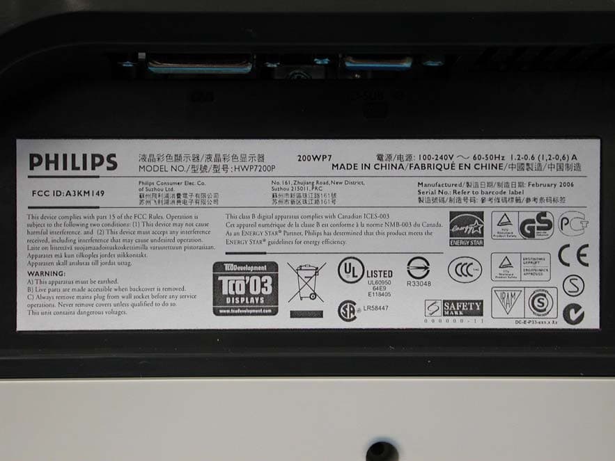
A3KM149
Mar 16, 200620� LCD Monitor
Equipment Class
JBP - Part 15 Class B Computing Device Peripheral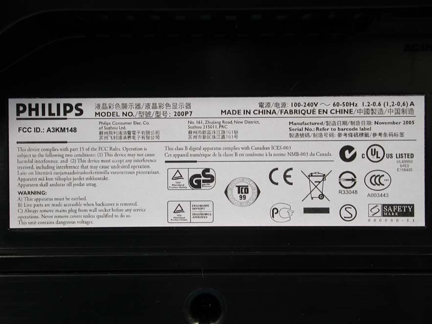
A3KM148
Dec 15, 200520
Equipment Class
JBP - Part 15 Class B Computing Device Peripheral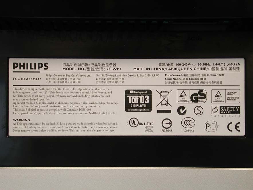
A3KM147
Nov 17, 2005LCD Monitor
Equipment Class
JBP - Part 15 Class B Computing Device Peripheral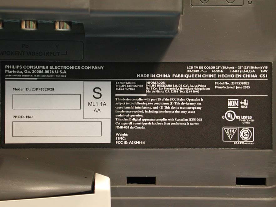
A3KM144
Jul 19, 2005LCD TV
Equipment Class
JBP - Part 15 Class B Computing Device Peripheral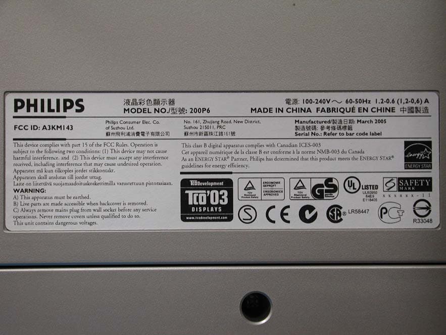
A3KM143
Apr 18, 2005Display Color Monitor
Equipment Class
JBP - Part 15 Class B Computing Device Peripheral