A3KM133LCD Monitor
Philips Electronics Industries (Taiwan) Ltd
Click to zoom
Application Details
- Equipment Class
- JBP - Part 15 Class B Computing Device Peripheral
- Date of Grant
- Mar 29, 2004
- Application Purpose
- Original Equipment
- Date of Application
- Mar 29, 2004
- Equipment Note
- LCD Monitor
- Country
- Taiwan
Documents & Files
Document Text
Text extracted from the exhibit documents filed with the FCC. Open a document above to read the original.
Users Manual
Product Information Product Features BRILLIANCE 230W5 The Best Productivity Solution z Outstanding front of screen performance {WUXGA, wide format 1920x1200 resolution for sharper display {Fast response time capable of handling fast moving pictures {Widest viewing angle up to 176 degree for extra efficiency z Maximum comfort for maximum productivity {Large viewing area for seeing more images without scrolling {Easy to access connections on a front to improve efficiency {Screen tilt and swivel adjustment for ideal viewing angle z Multi-function for ultimate convenience {A solid-state 6-in-1 media card reader for easy media access {Easy connection via hi-speed USB 2.0 Hub to any USB devices {Display from multiple video sources: YPbPr, S-Video and CVBS (230W5VS only) {PiP allows watching a second source simultaneously (230W5VS only) z Great convenience {Easy plug and play DVI ensures true digital experience {Embedded power supply eliminates external power adapters {VESA mounting pattern for easy wall mounting of display RETURN TO TOP OF THE PAGE Technical Specifications* LCD PANEL • TypeTFT LCD • Screen size23 inch / 58.4 cm • Pixel Pitch0.258 x 0.258 mm • LCD Panel type 1920 x 1200 pixels R.G.B. vertical stripe Anti-glare polarizer, hard coated • Effective viewing area495.36 x 309.6 mm • Display Colors8 bits interface (16.7M colors) SCANNING • Vertical refresh rate56Hz-85Hz • Horizontal Frequency30kHz-94kHz VIDEO < 205 MHz (Analog input) Exhibit 3 * This data is subject to change without notice. RETURN TO TOP OF THE PAGE Resolution and Preset Modes • Video dot rate< 165 MHz (Digital input) • Input impedance - Video 75 ohm + 3% - Sync 2.2K ohm • Input signal levels0.7 Vpp • Sync input signal Separate sync Composite sync Sync on green • Sync polaritiesPositive and negative • S-VideoY input 1.0Vpp, C input 0.3Vpp, 75ohm input impedance • CVBSComposite, 1.0Vpp, 75 ohm input impedance • Input Frequency WUXGA Hsync 75 kHz, Vsync 60 Hz (N.I.) WXGA Hsync 48 kHz, Vsync 60 Hz (N.I.) SVGA Hsync 38 kHz, Vsync 60 Hz (N.I.) VGA Hsync 31 kHz, Vsync 60 Hz (N.I.) • Video interface DVI-I, D-Sub, S-Video, composite and components video (YPbPr) AUDIO • Input level for PC/Video500mV nominal • Loudspeaker 6W Stereo Audio (3W/channel RMSx2, 200 Hz-10 kHz) Optical characteristics • Contrast ratio: 500:1 (typ.) • Brightness: 250 cd/m 2 (typ.) • White Chromaticity: x: 0.283 y: 0.297 (at 9300°K) x: 0.313 y: 0.329 (at 6500°K) • Viewing Angle (C/R>10) Upper >88° (typ.) Lower > 88° (typ.) Left > 88° (typ.) Right > 88° (typ.) • Response time 16 ms (typ.) • Maximum1920 x 1200 • Recommended 1920 x 1200 at 60Hz 20 factory preset modes: RETURN TO TOP OF THE PAGE Automatic Power Saving If you have VESA DPMS compliance display card or software installed in your PC, the monitor can automatically reduce its power consumption when not in use. If an input from a keyboard, mouse or other input device is detected, the monitor will 'wake up' automatically. The following table shows the power consumption and signaling of this automatic power saving feature: H. freq (kHz) Mode Resolution V. freq (Hz) 31.469 IBM VGA 10H 640x350 70.086 31.469 IBM VGA 3H 720x400 70.086 31.469 IBM VGA 12H 640x480 59.940 35.000 MACINTOSH 640x480 67.000 37.500 VESA 640x480 75.000 35.156 VESA 800x600 56.250 37.879 VESA 800x600 60.317 46.875 VESA 800x600 75.000 49.700 MACINTOSH 832x624 75.000 48.363 VESA 1024x768 60.004 60.023 VESA 1024x768 75.029 68.700 MACINTOSH 1152x870 75.000 71.810 SUN WS 1152x900 76.150 63.981 VESA 1280x1024 60.020 79.976 VESA 1280x1024 75.025 91.1 VESA 1280x1024 85.0 75.0 VESA 1600x1200 60.0 67.05 CVT 2.3MA 1920x1080 60.0 (for D-Sub) 74.56 CVT 2.3MA 1920x1200 60.0 (for D-Sub) 74.52 CVT 2.3MA-R 1920x1200 60.0 (for DVI) Power Management Definition VESA Mode Video H-sync V-sync Power Used LED color On Active Pulse Pulse 90W (typ.) Blue Off Blanked No No < 2.5W Amber DC Power OFF Not Active No No 2W Off This monitor is ENERGY STAR ® compliant. As an ENERGY STAR ® Partner, PHILIPS RETURN TO TOP OF THE PAGE Physical Specifications * This data is subject to change without notice. RETURN TO TOP OF THE PAGE Pin Assignment 1. The digital only connector contains 24 signal contacts organized in three rows of eight contacts. Signal pin assignments are listed in the following table: has determined that this product meets the E NERGY S TAR ® guidelines for energy efficiency. • Dimension (WxHxD) 548 x 452 x250 mm • Weight 9.0 Kg • Power supply90 — 264 VAC, 50/60 Hz • Power consumption 90 W (typ.) • Temperature0° C to 35° C • Relative humidity 20% to 80% • System MTBF50K hrs (excluding CCFL 40K hrs) Pin No. Signal Assignment Pin No. Signal Assignment Pin No. Signal Assignment 1 T.M.D.S. Data2- 9 T.M.D.S. Data1-17T.M.D.S. Data0- 2 T.M.D.S. Data2+ 10 T.M.D.S. Data1+18T.M.D.S. Data0+ 3 T.M.D.S. Data2/4 Shield 11 T.M.D.S. Data1/3 Shield 19 T.M.D.S. Data0/5 Shield 4 No connect 12 No connect 20No connect 5 No connect 13 No connect 21No connect 6 DDC Clock 14 +5V Power 22 T.M.D.S. Clock Shield 7 DDC Data 15 Ground (for +5V)23T.M.D.S. Clock+ 8 No connect 16 Hot Plug Detect24T.M.D.S. Clock- 2. The 15-pin D-sub connector (male) of the signal cable: RETURN TO TOP OF THE PAGE Product Views Follow the links to see various views of the monitor and its components. Front View Product Description RETURN TO TOP OF THE PAGE Physical Function Pin No. Assignment Pin No. Assignment 1 Red video input 9 +5V 2 Green video input/SOG 10 Cable detect 3 Blue video input 11 Identical output, connected to pin 10 4 Ground 12 Serial data line (SDA) 5 No connect 13 H. Sync / H+V 6 Red video ground 14 V. Sync 7 Green video ground 15 Data clock line (SCL) 8 Blue video ground RETURN TO TOP OF THE PAGE 1) Tilt 2) Swivel Installing Your LCD Monitor Front View Product Description RETURN TO TOP OF THE PAGE 1 To switch monitor's power On and Off 2 Power LED 3 To access OSD menu 4 To adjust the OSD 5 To adjust brightness of the display 6 To adjust the OSD 7 VOLUME To adjust speaker volume 8 AUT…
Text truncated - open the document above for the full version.
Block Diagram
Exhibit 4 Function Description for Hudson3-230W5 1. General The 23” UXGA TFT LCD monitor is specified as a display peripheral with analog, digital (DVI), CVBS, S-video, YPbPr and audio function. Horizontal scan range is 30KHz-94KHz for analog, and 30KHz-91KHz for digital. The refresh range is 56Hz-85Hz in normal mode. This scan range allows it to display resolution up to be 1920*1200@60Hz non-interlace input. The image can be adjusted by OSD control. These adjustments can be stored in an onboard memory. 2. Power supply Main voltage : AC 90-264V rms,50-60Hz Power consumption : 90W Max. Power indicator : LED(on: blue, standby: amber) Auto power saving : VESA DPMS 3. Input signal Horizontal scan : 30-94KHz(for analog), 30-94KHz(for digital) Vertical scan : 56-85Hz(from VGA to SXGA for analog/digital), Max. Vsync in UXGA for analog is 75Hz, Max. Vsync in UXGA for digital is 60Hz, Max. Vsync in WUXGA for analog and digital is 60Hz. Input signals : A. D-sub signal input level Video : 0.7Vp-p linear/75 ohms Sync : H/H+V,V TTL level,composite sync, sync on green B. Analog signal impedance Video : Terminated with 75 ohms Sync : Terminated with 2K2 ohms C. Intel DVI- digital Single channel TMDS signal D. CVBS Video : 1Vp-p linear/75 ohms Sync : composite sync 0.3Vp-p combined with video E. S-video Separated Luminance(Y) and Chrominance(C) signals Y input : 1.0Vp-p/75 ohms C input : 0.3Vp-p/75 ohms F. YPbPr : Separated Luminance(Y) and Chrominance(C) signals Y input : 700mV , 75 Ohm Pb, Pr input: +/- 350mV. 75 Ohm G. Audio Signal : PC audio lines respectively in Dsub and DVI L/R audio inputs respectively for CVBS/S and HDTV video 4. OSD( On Screen Display) function Software control function via OSD -Main controls: Language----------------- 6 Languages Adjust position-----------Horizontal,Vertical Adjust Size--------------- Full screen,Native mode,Fill with aspect Brightness & Contrast-- Brightness, Contrast Video Noise-------------- Phase, Clock Adjust color-------------- Original panel color,9300K,6500K,User preset OSD Settings------------- Horizontal,Vertical Product information----- Serial No,Resolution,Signal input Input selection------------Analog(D-SUB), Analog(DVI_A), Digital(DVI_D), CVBS, S-Video, HDTV Reset to factory setting-- No/Yes Exit Main controls 5. LCD Panel Type : 23” LCD flat panel Dimensions : 523(w)∗335.6(h)∗41(d) (Typ) mm Pitch : 0.258mmx0.258mm Color pixel arrangement : RGB vertical stripes Number of color : 256 gray level (8 bits) Backlight : 12 CCFL’s Active area (W*H) : 495.36x309.6mm 6. Function block ADC - Sample the input video signal according to its pixel rate to form a digital data TMDSRx - Convert serial digital signal to parallel digital RGB signal Video Decoder - Convert composite video( CVBS) & S-video signal to digital ITU601 format signal with YUV color space. HDTV - Convert component video(YPbPr) to digital ITU601 format signal with YUV color space. Scaler - Convert the image data from ADC,TMDSRx block or Video Decoder to LCD panel data format. - Zoom the input video to full screen display. Audio board - Provide audio in/out,volume control,earphone Control Board - Provide DCSW,/OKOSD,UP/Brightness+,Down/Brightness- ,Right/Volume+,Left/Volume-,Auto,INPUT,PIP. Power supply(Inverter embedded) - AC adapter : AC power input from 90VAC to 264VAC can generate +18VDC power - DC to DC converter : Convert +18V, +5V and +3.3V - Accept +18VDC voltage.(Inverter) Provide 750Vrms voltage for CCFL.(Inverter) 7. UCR1.0 (Universal Card Reader) - UCR(UNIVERSAL CARD READER) module is connected to PC by USB(B-type). - It’s also built-in 3-port USB Hub which can support two USB 1.1/2.0 devices. - As required by the USB 2.0 specification, the 3-port USB Hub is fully backward compatible with legacy full-speed devices. - Four type connections is needed: (1) 1*4 in 1 type flash memory card socket, support SMC/MMC/SD/MS/MS Pro card (2) 1* CF type flash memory card socket (3) 3 to USB devices(A-type), (4) one to PC(B-type). OS supports: (1) Windows 98SE, ME, 2000, XP (for USB 2.0) (2) MacOS X 10.1 and above (for USB2.0) (3) MacOS 9.1 and above (for USB 1.1 only) Scaler PW-181-30V AD Converter AD9888-205 Connector to panel TMDS TX Sil160CT100 D-SUB DDC EEPROM AC to DC Power Panel PWR 18V 3.3V/5V/18V, clk:68K Control BD DVI RX THC63DVI161 DVI-I DDC CVBS S-Video Flash ROM Video BD SAA7118E(7601) D_YUV Y Pb Pr HDTV BD AD 9883 (7652) Audio BD D_YUV 24bits ITU601 Controller MediaMemoryCard Pen-drive USB 2.0 PC UCR Elec. product specifications Elec. product specifications 230W5 Block Function 5V/18V 5V Crystal:14.318MHz (1401) Crystal: 24.576MHz( 1606) LPC921 Crystal:12MHz (1731) Crystal:12MHz Audio ( L/R) Audio ( L/R) Exhibit 5
External Photos
Exhibit 7 Photographs Front View Rear View Label
ID Label/Location Info
Exhibit 2 FCC ID Label
Internal Photos
Assembly w/o Back Cover Shielding Shielding Shielding Assembly w/o Shielding PCB Layout PCB Layout with shielding PCB Layout w/o shielding PCB Layout PCB Layout PCB Layout PCB Layout PCB Layout PCB Layout PCB Layout PCB Layout Assembly w/o PCB Plate LCD Panel Cables Cables
Test Report
FCC ID.A3KM133 Page 1 of 56 Audix Corporation. Report No. EM-F930050 TEST REPORT FOR CERTIFICATION On Behalf for Philips Electronics Industries (Taiwan) Ltd. Flat Panel Color Monitor Model No.: 230W5 FCC ID. : A3KM133 Brand : PHILIPS Prepared for : Philips Electronics Industries (Taiwan) Ltd. 5, Tze Chiang 1 Road, Chungli Industrial Park Chungli, Taoyuan, Taiwan, R.O.C. Prepared By : Audix Corporation Technical Division EMC Department No. 53-11, Tin-Fu Tsun, Lin-Kou, Taipei County, Taiwan, R.O.C. Tel : (02) 2609-9301, 2609-2133 Fax : (02) 2609-9303 File Number : EM930293 Report Number : EM-F930050 Date of Test : Mar. 05 ̑ 10, 2004 Date of Report : Mar. 12, 2004 FCC ID.A3KM133 Page 2 of 56 Audix Corporation. Report No. EM-F930050 TABLE OF CONTENTS Description Page TEST REPORT CERTIFICATION ......................................................................................................3 1. GENERAL INFORMATION..........................................................................................................4 1.1.Description of Device (EUT)..................................................................................................................... 4 1.2.Tested Supporting System Details............................................................................................................. 5 1.3.Description of Test Facility ....................................................................................................................... 8 1.4.Measurement Uncertainty.......................................................................................................................... 8 2. CONDUCTED EMISSION MEASUREMENT ............................................................................9 2.1.Test Equipment.......................................................................................................................................... 9 2.2.Block Diagram of Test Setup .................................................................................................................... 9 2.3.Conducted Emission Limit ( ̈15.107(a), Class B) ..................................................................................... 9 2.4.EUT‘s Configuration during Compliance Measurement ......................................................................... 10 2.5.Operating Condition of EUT ................................................................................................................... 10 2.6.Test Procedure ......................................................................................................................................... 11 2.7.Test Results.............................................................................................................................................. 11 3. RADIATED EMISSION MEASUREMENT...............................................................................40 3.1.Test Equipment........................................................................................................................................ 40 3.2.Block Diagram of Test Setup .................................................................................................................. 40 3.3.Radiation Limit ( ̈15.109/CISPR 22, Class B)........................................................................................ 41 3.4.EUT‘s Configuration during Compliance Measurement ......................................................................... 41 3.5.Operating Condition of EUT ................................................................................................................... 41 3.6.Test Procedure ......................................................................................................................................... 42 3.7.Radiated Emission Measurement Results................................................................................................ 43 4. DEVIATION TO TEST SPECIFICATIONS ..............................................................................47 5. PHOTOGRAPHS...........................................................................................................................48 5.1.Photos of Conducted Emission Measurement ......................................................................................... 48 5.2.Photos of Radiated Measurement at Semi-Anechoic Chamber (30-1000MHz)...................................... 51 5.3.Photos of Radiated Measurement at Open Field Test Site (30-1000MHz) ............................................. 54 5.4.Photos of Radiated Measurement at Open Field Test Site (1-2GHz) ...................................................... 56 APPENDIX (Radiated Emission Measurement Data at Semi-Anechoic Chamber) FCC ID.A3KM133 Page 3 of 56 Audix Corporation. Report No. EM-F930050 TEST REPORT CERTIFICATION Applicant : Philips Electronics Industries (Taiwan) Ltd. Manufacturer #1 : Philips Electronics Industries (Taiwan) Ltd. Manufacturer #2 : Skyway (Dong Guan) Monitor Factory Manufacturer #3 : Philips Consumer Electronics Co., of Suzhou Ltd. Manufacturer #4 : Philips Monitors Manufacturing Hungary EUT Description : Flat Panel Color Monitor FCC ID. :A3KM133 (A) MODEL NO. : 230W5 (B) SERIAL NO. : TY0404026 (C) BRAND : PHILIPS (D) POWER SUPPLY :AC 100V-240V~ , 60-50Hz, 1.6-0.8A (Test Voltage: AC 120V/60Hz) Measurement Procedure Used: FCC 47 CFR, Part 15, Subpart B / Dec. 2003 and CISPR 22 / 1997 ANSI C63.4 / 2001 The device described above was tested by Audix Corporation to determine the maximum emission levels emanating from the device. The maximum emission levels were compared to the CISPR 22 Class B radiated emission limit below 1GHz against the 15.109(g) of FCC Part 15 and 15.109(a) of FCC Part 15 limit above 1GHz, and compared to the conducted emission limit of 15.107(a) of FCC Part 15. The measurement results are contained in this test report and Audix Corporation is assumed full responsibility for the accuracy…
Text truncated - open the document above for the full version.
Test Report
FCC ID.A3KM133 APPENDIX Audix Corporation. Report No. EM-F930050 APPENDIX (Radiated Emission Measurement at Semi-Anechoic Chamber) Total Pages: 28 Pages FCC ID.A3KM133 APPENDIX Page 1 of 28 Audix Corporation. Report No. EM-F930050 FCC ID.A3KM133 APPENDIX Page 2 of 28 Audix Corporation. Report No. EM-F930050 FCC ID.A3KM133 APPENDIX Page 3 of 28 Audix Corporation. Report No. EM-F930050 FCC ID.A3KM133 APPENDIX Page 4 of 28 Audix Corporation. Report No. EM-F930050 FCC ID.A3KM133 APPENDIX Page 5 of 28 Audix Corporation. Report No. EM-F930050 FCC ID.A3KM133 APPENDIX Page 6 of 28 Audix Corporation. Report No. EM-F930050 FCC ID.A3KM133 APPENDIX Page 7 of 28 Audix Corporation. Report No. EM-F930050 FCC ID.A3KM133 APPENDIX Page 8 of 28 Audix Corporation. Report No. EM-F930050 FCC ID.A3KM133 APPENDIX Page 9 of 28 Audix Corporation. Report No. EM-F930050 FCC ID.A3KM133 APPENDIX Page 10 of 28 Audix Corporation. Report No. EM-F930050 FCC ID.A3KM133 APPENDIX Page 11 of 28 Audix Corporation. Report No. EM-F930050 FCC ID.A3KM133 APPENDIX Page 12 of 28 Audix Corporation. Report No. EM-F930050 FCC ID.A3KM133 APPENDIX Page 13 of 28 Audix Corporation. Report No. EM-F930050 FCC ID.A3KM133 APPENDIX Page 14 of 28 Audix Corporation. Report No. EM-F930050 FCC ID.A3KM133 APPENDIX Page 15 of 28 Audix Corporation. Report No. EM-F930050 FCC ID.A3KM133 APPENDIX Page 16 of 28 Audix Corporation. Report No. EM-F930050 FCC ID.A3KM133 APPENDIX Page 17 of 28 Audix Corporation. Report No. EM-F930050 FCC ID.A3KM133 APPENDIX Page 18 of 28 Audix Corporation. Report No. EM-F930050 FCC ID.A3KM133 APPENDIX Page 19 of 28 Audix Corporation. Report No. EM-F930050 FCC ID.A3KM133 APPENDIX Page 20 of 28 Audix Corporation. Report No. EM-F930050 FCC ID.A3KM133 APPENDIX Page 21 of 28 Audix Corporation. Report No. EM-F930050 FCC ID.A3KM133 APPENDIX Page 22 of 28 Audix Corporation. Report No. EM-F930050 FCC ID.A3KM133 APPENDIX Page 23 of 28 Audix Corporation. Report No. EM-F930050 FCC ID.A3KM133 APPENDIX Page 24 of 28 Audix Corporation. Report No. EM-F930050 FCC ID.A3KM133 APPENDIX Page 25 of 28 Audix Corporation. Report No. EM-F930050 FCC ID.A3KM133 APPENDIX Page 26 of 28 Audix Corporation. Report No. EM-F930050 FCC ID.A3KM133 APPENDIX Page 27 of 28 Audix Corporation. Report No. EM-F930050 FCC ID.A3KM133 APPENDIX Page 28 of 28 Audix Corporation. Report No. EM-F930050
Test Setup Photos
FCC ID.A3KM133 Page 48 of 56 Audix Corporation. Report No. EM-F930050 5. PHOTOGRAPHS 5.1. Photos of Conducted Emission Measurement Test Mode: D-Sub, DVI Input (“H” Pattern) FRONT VIEW OF CONDUCTED MEASUREMENT Test Mode: A/V, S-Video Input (Image “Color Bar”) FRONT VIEW OF CONDUCTED MEASUREMENT FCC ID.A3KM133 Page 49 of 56 Audix Corporation. Report No. EM-F930050 Test Mode: Component Input (Image “DVD Movie”) FRONT VIEW OF CONDUCTED MEASUREMENT Test Mode: DVI+A/V Input (PIP, “H” Pattern + Image “Color Bar”) FRONT VIEW OF CONDUCTED MEASUREMENT FCC ID.A3KM133 Page 50 of 56 Audix Corporation. Report No. EM-F930050 BACK VIEW OF CONDUCTED MEASUREMENT FCC ID.A3KM133 Page 51 of 56 Audix Corporation. Report No. EM-F930050 5.2. Photos of Radiated Measurement at Semi-Anechoic Chamber (30-1000MHz) Test Mode: D-Sub, DVI Input (“H” Pattern) FRONT VIEW OF RADIATED MEASUREMENT Test Mode: A/V, S-Video Input (Image “Color Bar”) FRONT VIEW OF RADIATED MEASUREMENT FCC ID.A3KM133 Page 52 of 56 Audix Corporation. Report No. EM-F930050 Test Mode: Component Input (Image “DVD Movie”) FRONT VIEW OF RADIATED MEASUREMENT Test Mode: DVI+A/V Input (PIP, “H” Pattern + Image “Color Bar”) FRONT VIEW OF RADIATED MEASUREMENT FCC ID.A3KM133 Page 53 of 56 Audix Corporation. Report No. EM-F930050 BACK VIEW OF RADIATED MEASUREMENT FCC ID.A3KM133 Page 54 of 56 Audix Corporation. Report No. EM-F930050 5.3. Photos of Radiated Measurement at Open Field Test Site (30-1000MHz) Test Mode: 1920*1200/60Hz, 75kHz, DVI Input (“H” Pattern) FRONT VIEW OF RADIATED MEASUREMENT BACK VIEW OF RADIATED MEASUREMEMT FCC ID.A3KM133 Page 55 of 56 Audix Corporation. Report No. EM-F930050 SETUP WITH MAXIMUM DETECTED EMISSION AT HORIZONTAL POLARIZATION SETUP WITH MAXIMUM DETECTED EMISSION AT VERTICAL POLARIZATION FCC ID.A3KM133 Page 56 of 56 Audix Corporation. Report No. EM-F930050 5.4. Photos of Radiated Measurement at Open Field Test Site (1-2GHz) FRONT VIEW OF RADIATED MEASUREMENT BACK VIEW OF RADIATED MEASUREMENT
Contact Information
Applicant
Ronnie Yang(Manager, Safety/DEV)
Test Firm
Audix Technology CorporationJeff Chen
Technical Specifications
| # | Rule Parts | Frequency Range | Power Output |
|---|---|---|---|
| 1 | 15B | - | - |
Other Applications from Philips Electronics Industries (Taiwan) Ltd
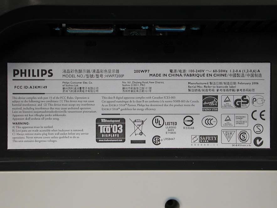
A3KM149
Mar 16, 200620� LCD Monitor
Equipment Class
JBP - Part 15 Class B Computing Device Peripheral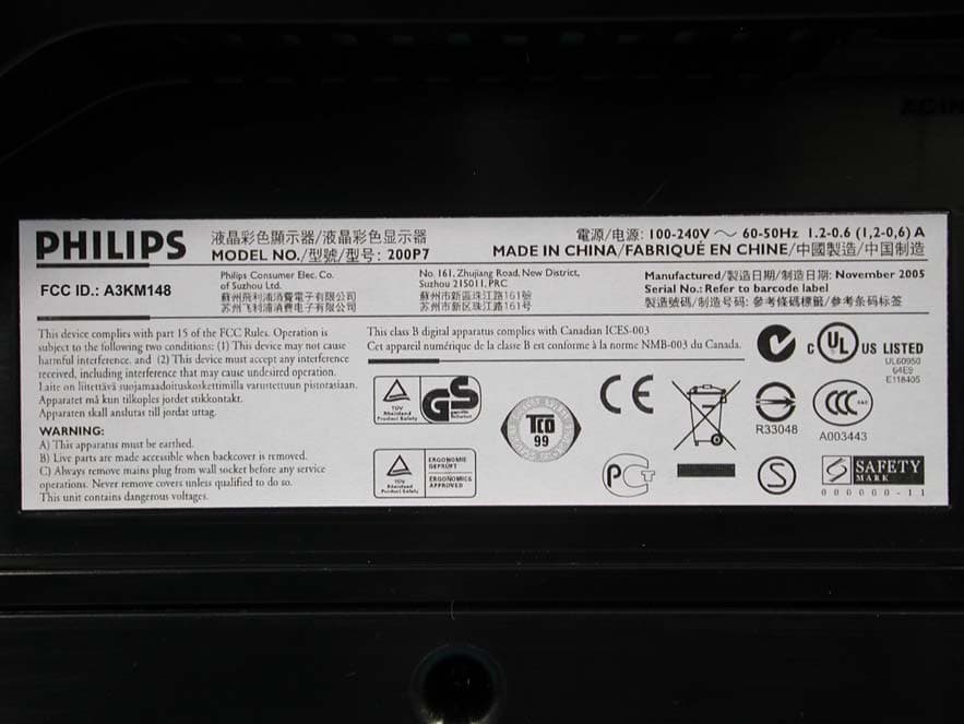
A3KM148
Dec 15, 200520
Equipment Class
JBP - Part 15 Class B Computing Device Peripheral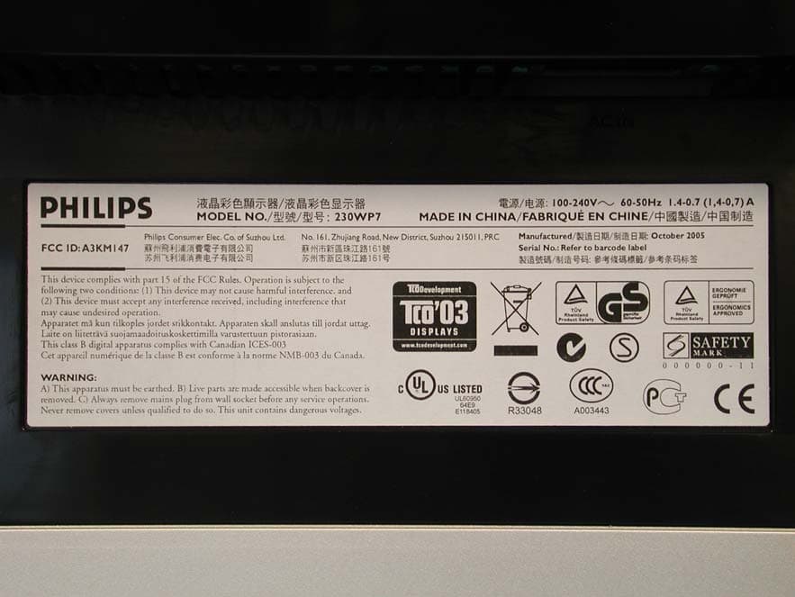
A3KM147
Nov 17, 2005LCD Monitor
Equipment Class
JBP - Part 15 Class B Computing Device Peripheral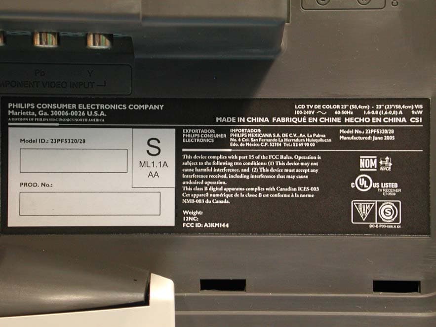
A3KM144
Jul 19, 2005LCD TV
Equipment Class
JBP - Part 15 Class B Computing Device Peripheral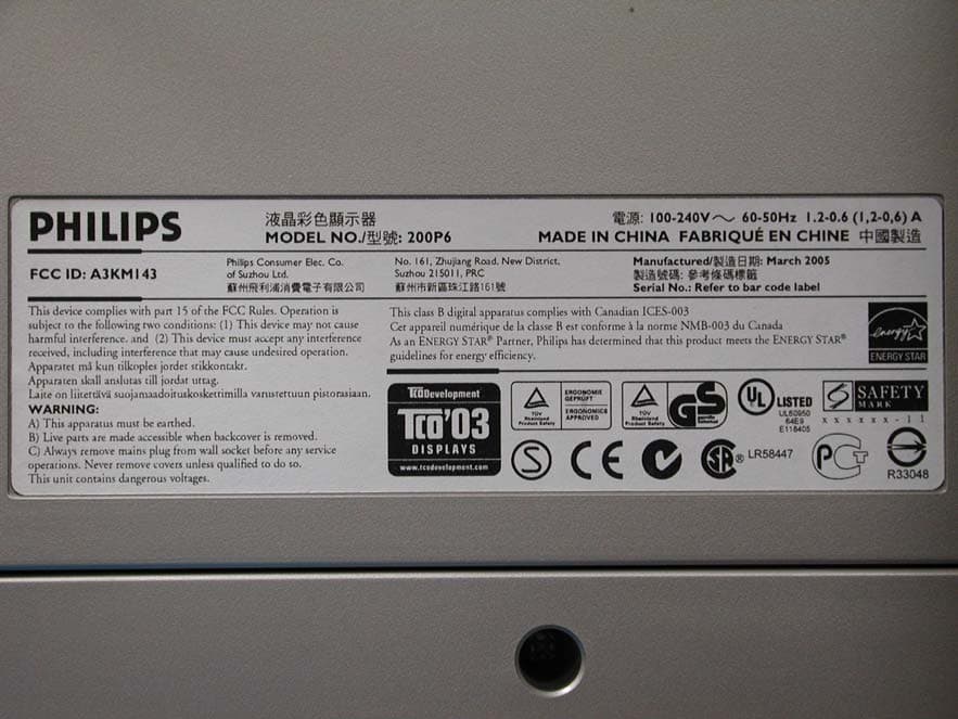
A3KM143
Apr 18, 2005Display Color Monitor
Equipment Class
JBP - Part 15 Class B Computing Device Peripheral