A3KM134Color Monitor
Philips Electronics Industries (Taiwan) Ltd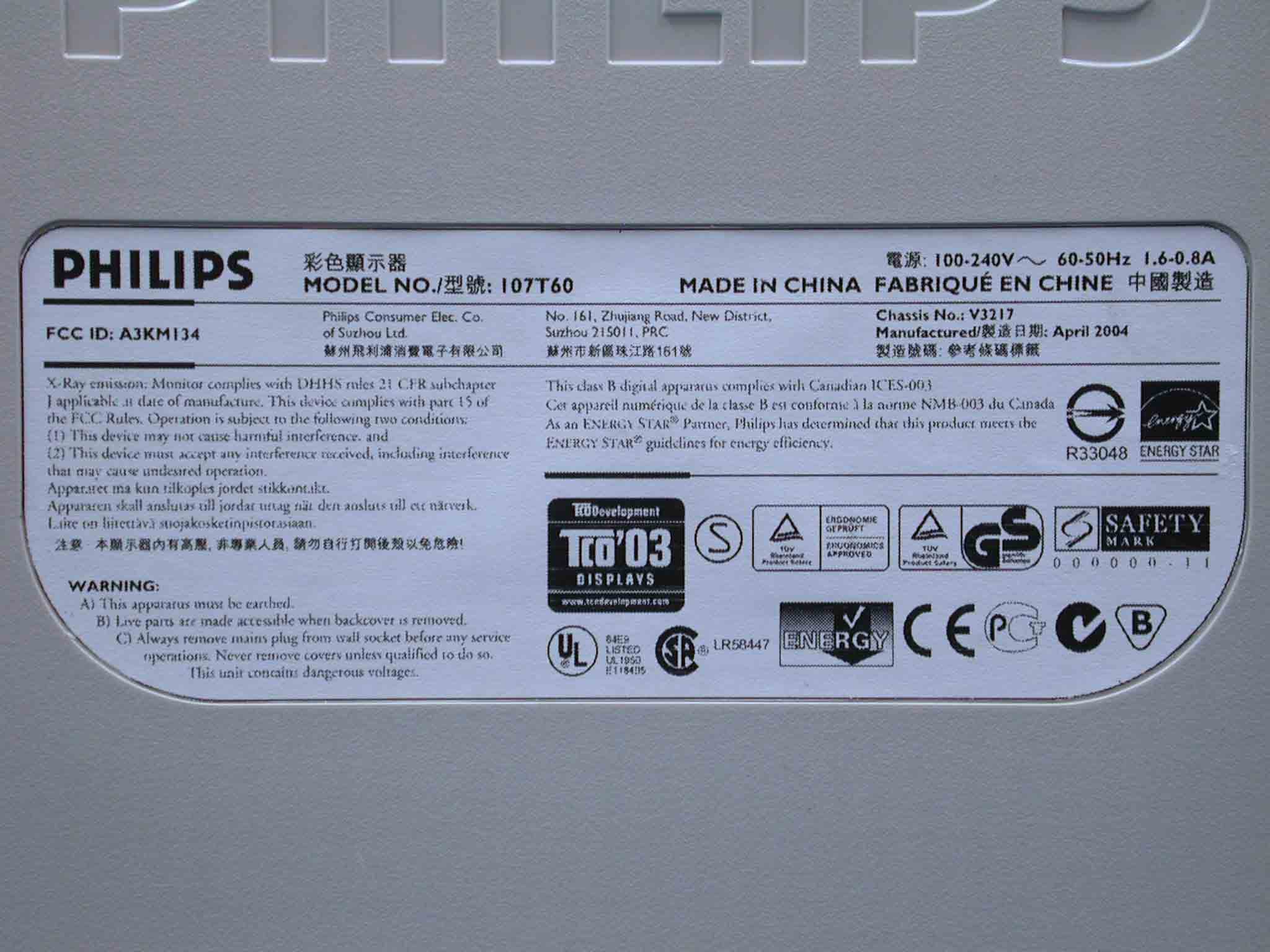
Click to zoom
Application Details
- Equipment Class
- JBP - Part 15 Class B Computing Device Peripheral
- Date of Grant
- May 02, 2004
- Application Purpose
- Original Equipment
- Date of Application
- May 02, 2004
- Equipment Note
- Color Monitor
- Country
- Taiwan
Documents & Files
Document Text
Text extracted from the exhibit documents filed with the FCC. Open a document above to read the original.
Users Manual
Product Information Product Features • LightFrame™ for Windows • Technical Specifications • Automatic Power Saving • Physical Specification • Pin Assignment • Product Views Product Features 107T6 z17-inch (16.0" VIS) color monitor with excellent front of screen performance for use with MACs and PCs zAutoscan covers horizontal frequencies up to 71 kHz offering a maximum resolution of 1280 x 1024 with flicker free display of 1024 x 768 at up to 89 Hz. zReal Flat High Contrast CRT with high-resolution 0.25 mm dot pitch (0.21 hdp) zLightFrame™ for brightest and sharpest display of movie and photo windows . zLarge screen display in a small footprint: 17-inch conventional monitor with maximum depth of only 424 mm/16.7" zMultimedia Base option . zsRGB for true on screen color representation. zFCC, CE (in selected countries only) and ISO9241, ISO14001 certified RETURN TO TOP OF THE PAGE LightFrame™ for Windows Introduction Philips LightFrame™ feature enriches the experience of pictures and video on a Philips CRT (picture tube) monitor. LightFrame™ will boost the brightness and sharpness of photos and videos on the monitor screen. To control the LightFrame™ feature in your monitor, you have to install the LightFrame™ application which you will find on this CD-ROM. Model Regulation Color 107T60 TCO'03 Gray 107T61 MPRII Gray 107T66 MPRII Black Exhibit 3 Note Philips LightFrame™ will only work with monitors that have been built to use this software. Earlier Philips monitors or other manufacturers’ monitors will not work with this special software. It is recommended that you install this software only on a Philips monitor designed to use it. These monitors can be identified by the LightFrame™ logo on the front of the monitor. This software is not designed for use with LCD flat screen monitors. LightFrame™ will work with true Windows-based programs and DOS-based programs that operate in a Windows environment. It will not work with DOS-based programs operating only in a DOS environment. Language Selection While English is the default language of LightFrame™, the User Interface can be set up to operate in Dutch, French, German, Italian, Portuguese, Spanish, Simplified Chinese, Traditional Chinese or Korean. Installation 1) To install LightFrame™, place the CD in the CD-ROM drive. 2) Next, when the menu of items on the CD appears on your screen, click on 'Install LightFrame™'. 3) Now, follow the on-screen prompts to properly install the program. The software checks to see if you have a compatible monitor. You must agree to the license agreement terms for the software to install. 4) After installation, LightFrame™ automatically loads and the icon appears in the taskbar. Notes If LightFrame™ detects that your monitor is not LightFrame™ compatible, a message appears on the monitor screen. If you see this message, you can select to abort or continue the installation. However, if you continue the installation, LightFrame™ will probably not work on the monitor. How to use LightFrame™ After installation, LightFrame™ starts up automatically whenever the computer is started. For information about using LightFrame™ please refer to the help information which is available after installation. Compatibility This version of LightFrame™ is compatible with Windows® 95 Windows® 98 Windows® Me (Millenium Edition) Windows® XP Windows® 2000 Professional Edition. LightFrame™ 3 -- Frequently Asked Questions (and answers) LightFrame™ Q: Is LightFrame™ 2 compatible with LightFrame™ 3? A: No. If you run LightFrame&trade ; 1 or 2 software with a Philips LightFrame™ 3 monitor, nothing will happen. Q:Can I use LightFrame™ 3 software on my LightFrame™ 1 / 2 monitor. A: No for a LightFrame™ 1 or 2 monitor you need to use LightFrame™ 1 or 2 software. It is however possible to use the LightFrame™ 2 software on a LightFrame™ 1 monitor. Q:What is the difference between LightFrame™ 1, LightFrame™ 2 and LightFrame™ 3? A: LightFrame™ 1 was the very first generation of the LightFrame™ feature introduced by Philips. In that version the user needs to manually turn on/off the feature and select the window or area to apply it to. LightFrame™ 2 offers the automatic detection in Internet Explorer on top of the LightFrame™ 1 functions. With this feature LightFrame™ will automatically scan a web page in Internet Explorer, find the largest picture and enhance it. LightFrame™ 3 offers everything that LightFrame™ 2 has but now with the possibility to enhance multiple pictures at the same time. So in a web page LightFrame™ will find all the pictures and enhance them simultaneously or in a photo viewing application you can enhance multiple photos at once. Furthermore LightFrame™ 3 comes with an easy to activate full screen function. This is especially handy for games and movies. Just one click on the full screen button and LightFrame™ enhances your total monitor. Q:Can I upgrade my current Philips monitor to LightFrame™ 3? A: No. For LightFrame™ 3 Philips developed special hardware which is build into the monitor. Therefore upgrading from LightFrame™ 1 or 2 to 3 is not possible. It is however possible to upgrade your LightFrame™ 1 monitor to LightFrame™ 2 by installing the LightFrame™ 2 software. Q:Can I install LightFrame™ 3 over an older version? A: When you install LightFrame™ 3 the setup wizard will scan your system to check if you have an older version installed. If so, the setup wizard will remove that version before continuing with the installation of the new version. Please be aware that for LightFrame™ 3 you also need a monitor which is capable of running the LightFrame™ 3 feature. Q:How can I tell which version LightFrame™ my monitor can support? A: To check which version of LightFrame™ is supported by your monitor check the LightFrame logo which you will find on the top, right-hand corner of the monitor. If this logo has a small 3 in it, your monitor is ready for LightFrame™ 3. Otherwise you should use the LightFrame™ 1 or 2 software. Q: How ma…
Text truncated - open the document above for the full version.
Block Diagram
1 Exhibit 4 V32 107T6 Brief Circuit Description 0. Functional Block Diagram 1. General Description 2. Description of Circuit Diagram A. Power Supply & Power Saving Management B. Horizontal Deflection/Vertical Deflection/EHT Generator C. Video board & DDC 2B D. Digital Circuit & Micro-controller 2 GENERAL DESCRIPTION V32 107T5, using 17” flat High Brightness CRT, are so-called “Digital Controlled Auto-scan Color Display Monitor” with high resolution which can operate at horizontal scan frequency from 30KHz up to 71KHz, and vertical scan frequencies from 50 to 160 Hz. It adopts a brand new Demic IC – SAA4848, made by Philips, which incorporates Deflection and Micro-controller in one chip with 56 pins. The monitor is equipped with an embedded micro-controller (included in Demic IC), which can preset the required modes. It also provides many functions, such as digital adjustable picture, DDC2B, power management, sRGB, low emission, high immunity, ---- etc. The monitor complies with TCO99/TCO’03/MPRII low emission standard and also fulfill E2000 automatic power saving requirements, to reduce power consumption to less than 1 watts in power saving mode. The monitor also complies with VESA standard and energy star computer program initiated by the EPA. 1. DESCRIPTION OF CIRCUIT DIAGRAM This description mainly introduces the functions including power supply, power saving management, horizontal / vertical deflection, video amplifier, and micro- controller, etc. A. POWER SUPPLY / POWER SAVING MANAGEMENT The monitor is designed to adopt switching mode power supply which can operate mains input from 90VAC to 264VAC. This switching power supply applies an IC TEA1507. The control scheme transforms a rectified voltage source into a multi- output voltages. The control concept exhibits many desirable properties such as inherent over-load protection, stable and fast system response. A current sense circuit (R3107/08/09, etc) is equipped for power limiting (90W) and safety reason on primary power supply circuit. Secondary feedback via a photo-coupler is used to obtain a stable output voltages. The secondary outputs supply all necessary voltages for deflection and video and micro-controller. Power transformer and peripheral ckt are same as 107T5. The main differences are 7153, which has been changed from L78L05ACZ in TO92 package to L7805CV in TO220 package, and 7151, which has been changed from BC338 to BC638, due to the larger load of +5V line because of the use of Demic IC which is supplied +5V. All rectified diodes on secondary site are without lead frame ( heat-sink), it gains some cost saving in thermal design, but the turn ratios of main transformer should be well determined to maintain an adequate voltage derating of primary switching MOSFET and secondary +190V rectified diode BYV26E (with better thermal performance).This is trade-off design in between. The other hand, a secondary DC power switch (tact sw) is adopted. And B+190V adjustment is not needed. A fixed resistor (3162), same as 107T5, is still used.. 3 This monitor can save power consumption while no sync pulses and automatically recover to normal power-on when sync signals are detected by micro-controller. The power saving off mode still exists in new designed monitors, but suspend / stand-by mode are deleted due to patent infringement issue. During Off mode, LED will flash and all the output voltages of main power are reduced to a very low level, and the operating frequency also comes very low, and only the required voltage of Demic IC (+5V) is supplied. When the monitor is switched off it is actually in burst mode (< 1W). B. HORIZONTAL DEFLECTION / VERTICAL DEFLECTION / EHT GENERATOR HORIZONTAL DEFLECTION: The heart of horizontal/vertical deflection controller is Demic IC - SAA4848, which can offer a complete and efficient small signal sync processing for auto-sync monitors. All functions are controlled via I2C bus. This controller provides sync processing, which can accept separate and composite (H+V) input signals. A very short settling time after mode change for protection of external power components has been taken into account. However, it should be noted that according to V32 107T6 spec this monitor doesn’t support composite (H+V) input signals to avoid some troubles. The SAA4848 provides extensive functions like a flexible B+ controller block of H- deflection and a geometry control with facility, leading to excellent picture quality. This device also can directly drive the vertical deflection output stage. The line driver stage, the E/W output stage and all controls are tracked with the incoming frequencies. Picture can be adjusted along horizontal/vertical direction by OSD H- shift/V-shift control. The horizontal size, east/west, trapezoid corrections can be adjusted by the output of pin35 (EWout), which is led to the diode modulation circuit. S-capacitors plus power MOSFET switches and DC controlled linearity coil are designed for optimal picture linearity. VERTICAL DEFLECTION: The majority of vertical deflection function is integrated by two ICs : SAA4848 and TDA4863. The SAA4848 takes care of sync polarity correction, automatic catching and holding of the vertical oscillator, generation of saw-tooth drive current for vertical output and vertical s-correction, and generation of a correct V-blanking pulse for video blanking during vertical retrace time. 4 The TDA4863 is a DC-coupled vertical deflection booster with differential input signals, suitable for color monitors. The output stage has thermal and soar protection, and high linear saw-tooth signal amplification to obtain the required vertical deflection current. The voltage supply at flyback time for output stage is generated by the internal flyback generator and the external diode (6401) and capacitor (2405) which make the so-called pump-up circuit. EHT GENERATOR The IC SAA4848 is also used as a controller to generate required extra high voltage for CRT via a buck converter…
Text truncated - open the document above for the full version.
Cover Letter(s)
FCC ID. A3KM134 APPENDIX II Audix Corporation. Report No. EM-F930062 APPENDIX II (The Details of Difference for all Models) Total Pages1 FCC ID. A3KM134 APPENDIX II 1/1 Audix Corporation. Report No. EM-F930062 The Details of Difference List Model Region TCO/MPR Cabinet Color Base Light Frame CRT 107T60 Global TCO’03 Gray Normal Base Yes 107T61 Global MPR II Gray Normal Base Yes 107T65 Global TCO’99 Black Normal Base Yes 107T66 Global MPR II Black Normal Base Yes (1) LG Philips, M/N M41QEE903X04 (2) LG Philips (HF), M/N M41FJB523X140 (3) SDI, M/N M41QCJ761X172 (4) CPT, M/N M41AJR53X76 107C63 AP/Latam TCO’03 Front cabinet: all Silver, Black Cover: Black Four Claw Base Yes 107C64 AP/Latam TCO’99 Front Cabinet: Silver with Back Frame, Back Cover: Black Four Claw Base Yes 107C65 AP/Latam TCO’99 Black Four Claw Base Yes (1) LG Philips, M/N M41QEE903X04 (2) LG Philips (HF), M/N M41FJB523X140 (3) SDI, M/N M41QCJ761X172 (4) CPT, M/N M41AJR53X76 107S60 AP TCO’03 Gray Normal Base Yes 107S61 AP/Latam MPR II Gray Normal Base Yes 107S66 AP/Latam MPR II Black Normal Base Yes 107S67 China MPR II Blue/Silver Normal Base Yes (1) LG Philips, M/N M41QEE903X04 (2) LG Philips (HF), M/N M41FJB523X140 (3) SDI, M/N M41QCJ761X172 (4) CPT, M/N M41AJR53X76
External Photos
Exhibit 7 Photographs Front View Rear View Label
ID Label/Location Info
Exhibit 2 FCC ID Label
Internal Photos
Top View Without Back Cover Side View Without Back Cover Side View Without Back Cover Shielding CRT Assembly PCB Layout PCB Layout PCB Layout PCB Layout Power Cord and I/F Cables
Test Report
FCC ID. A3KM134 Page 1 of 53 Audix Corporation. Report No. EM-F930062 APPLICATION FOR CERTIFICATION On Behalf of Philips Electronics Industries (Taiwan) Ltd. Color Monitor Model No.(1)107T60 (2)107T61 (3)107T65 (4)107T66 (5)107C63 (6)107C64 (7)107C65 (8)107S60 (9)107S61 (10)107S66 (11)107S67 FCC ID: A3KM134 Brand : Philips Prepared for : Philips Electronics Industries (Taiwan) Ltd. 5, Tze Chiang 1 Rd, Chungli Ind. Park, Chungli, Taoyuan Hsien, Taiwan, R.O.C. Prepared By : AUDIX Corporation Technical Division EMC Department No. 53-11, Tin-Fu Tsun, Lin-Kou, Taipei Hsien, Taiwan, R.O.C. Tel: (02) 2609-9301, 2609-2133 Fax: (02) 2609-9303 File Number EM930391 Report Number EM-F930062 Date of Test Apr. 01 ~ 07, 2004 Date of Report Apr. 08, 2004 FCC ID. A3KM134 Page 2 of 53 Audix Corporation. Report No. EM-F930062 TABLE OF CONTENTS Description Page Test Report Certification........................................................................................................................3 1. GENERAL INFORMATION...........................................................................................................4 1.1. Description of Device (EUT)...........................................................................................................4 1.2. Tested Supporting System Details....................................................................................................5 1.3. Test Facility...................................................................................................................................7 1.4. Measurement Uncertainty...............................................................................................................7 2. CONDUCTED DISTURBANCE MEASUREMENT.....................................................................8 2.1. Test Equipment..............................................................................................................................8 2.2. Block Diagram of Test Setup...........................................................................................................8 2.3. Powerline Conducted Emission Limit (15.107, Class B)....................................................................8 2.4. EUT’s Configuration during Compliance Measurement....................................................................9 2.5. Operating Condition of EUT.........................................................................................................10 2.6. Test Procedure..............................................................................................................................10 2.7. Test Results..................................................................................................................................11 3. RADIATED DISTURBANCE MEASUREMENT.......................................................................36 3.1. Test Equipment............................................................................................................................36 3.2. Block Diagram of Test Setup.........................................................................................................36 3.3. Radiation Limit (15.109/CISPR 22, Class B)..................................................................................37 3.4. EUT’s Configuration during Compliance Measurement..................................................................37 3.5. Operating Condition of EUT.........................................................................................................37 3.6. Test Procedure..............................................................................................................................38 3.7. Radiated Emission Measurement Results.......................................................................................39 4. DEVIATION TO TEST SPECIFICATIONS...............................................................................48 5. PHOTOGRAPHS............................................................................................................................49 5.1. Photos of Powerline Conducted Measurement................................................................................49 5.2. Photos of Radiated Measurement at Semi-Anechoic Chamber (30~1000MHz).................................50 5.3. Photos of Radiated Measurement at Open Field Test Site (30~1000MHz)........................................51 5.4. Photos of Radiated Measurement at Semi-Anechoic Chamber (Above 1GHz)..................................53 APPENDIX I (Radiated Test Data at Semi-Anechoic Chamber) APPENDIX II (The Details of Difference for all Model) FCC ID. A3KM134 Page 3 of 53 Audix Corporation. Report No. EM-F930062 TEST REPORT CERTIFICATION Applicant Philips Electronics Industries (Taiwan) Ltd. Manufacturer Philips Electronics Industries (Taiwan) Ltd. EUT Description Color Monitor FCC ID A3KM134 (A) MODEL NO. (1)107T60 (2)107T61 (3)107T65 (4)107T66 (5)107C63 (6)107C64 (7)107C65 (8)107S60 (9)107S61 (10)107S66 (11)107S67 (B) SERIAL NO. (1)TY0404095 (2)TY0404096 (3)TY0404099 (4)TY0404104 (C) BRAND NAME Philips (D) POWER SUPPLY AC 100-240V~ 60-50Hz (Test Voltage: AC 120V/60Hz) Measurement Standard Used: FCC Part 15B / Dec. 2003 and CISPR 22/1997 and ANSI C63.4-2001 The device described above was tested by AUDIX Corporation determine the maximum emission levels emanating from the device. The maximum emission levels were compared to the CISPR 22 Class B radiated emission limit against the 15.109(g) of FCC Part 15 for 1GHz below, compared the FCC Part 15 subject B radiated limit for above 1GHz and the conducted emission limit of 15.107 (a) of FCC Part 15. The measurement results are contained in this test report and AUDIX Corporation is assumed full responsibility for the accuracy and completeness of these measurements. Also, this report shows that the EUT to be technically compliance with the FCC official limits. This report applies to abo…
Text truncated - open the document above for the full version.
Test Report
FCC ID. A3KM134 APPENDIX I Audix Corporation. Report No. EM-F930062 APPENDIX I (Radiated Test Data at Semi-Anechoic Chamber) Total Pages24 FCC ID. A3KM134 APPENDIX I 1/24 Audix Corporation. Report No. EM-F930062 FCC ID. A3KM134 APPENDIX I 2/24 Audix Corporation. Report No. EM-F930062 FCC ID. A3KM134 APPENDIX I 3/24 Audix Corporation. Report No. EM-F930062 FCC ID. A3KM134 APPENDIX I 4/24 Audix Corporation. Report No. EM-F930062 FCC ID. A3KM134 APPENDIX I 5/24 Audix Corporation. Report No. EM-F930062 FCC ID. A3KM134 APPENDIX I 6/24 Audix Corporation. Report No. EM-F930062 FCC ID. A3KM134 APPENDIX I 7/24 Audix Corporation. Report No. EM-F930062 FCC ID. A3KM134 APPENDIX I 8/24 Audix Corporation. Report No. EM-F930062 FCC ID. A3KM134 APPENDIX I 9/24 Audix Corporation. Report No. EM-F930062 FCC ID. A3KM134 APPENDIX I 10/24 Audix Corporation. Report No. EM-F930062 FCC ID. A3KM134 APPENDIX I 11/24 Audix Corporation. Report No. EM-F930062 FCC ID. A3KM134 APPENDIX I 12/24 Audix Corporation. Report No. EM-F930062 FCC ID. A3KM134 APPENDIX I 13/24 Audix Corporation. Report No. EM-F930062 FCC ID. A3KM134 APPENDIX I 14/24 Audix Corporation. Report No. EM-F930062 FCC ID. A3KM134 APPENDIX I 15/24 Audix Corporation. Report No. EM-F930062 FCC ID. A3KM134 APPENDIX I 16/24 Audix Corporation. Report No. EM-F930062 FCC ID. A3KM134 APPENDIX I 17/24 Audix Corporation. Report No. EM-F930062 FCC ID. A3KM134 APPENDIX I 18/24 Audix Corporation. Report No. EM-F930062 FCC ID. A3KM134 APPENDIX I 19/24 Audix Corporation. Report No. EM-F930062 FCC ID. A3KM134 APPENDIX I 20/24 Audix Corporation. Report No. EM-F930062 FCC ID. A3KM134 APPENDIX I 21/24 Audix Corporation. Report No. EM-F930062 FCC ID. A3KM134 APPENDIX I 22/24 Audix Corporation. Report No. EM-F930062 FCC ID. A3KM134 APPENDIX I 23/24 Audix Corporation. Report No. EM-F930062 FCC ID. A3KM134 APPENDIX I 24/24 Audix Corporation. Report No. EM-F930062
Test Setup Photos
FCC ID. A3KM134 Page 49 of 53 Audix Corporation. Report No. EM-F930062 5. PHOTOGRAPHS 5.1. Photos of Powerline Conducted Measurement FRONT VIEW OF CONDUCTED TEST BACK VIEW OF CONDUCTED TEST FCC ID. A3KM134 Page 50 of 53 Audix Corporation. Report No. EM-F930062 5.2. Photos of Radiated Measurement at Semi-Anechoic Chamber (30~1000MHz) FRONT VIEW OF RADIATED TEST BACK VIEW OF RADIATED TEST FCC ID. A3KM134 Page 51 of 53 Audix Corporation. Report No. EM-F930062 5.3. Photos of Radiated Measurement at Open Field Test Site (30~1000MHz) Test Mode1280*1024/60Hz, 64kHz FRONT VIEW OF RADIATED TEST BACK VIEW OF RADIATED TEST FCC ID. A3KM134 Page 52 of 53 Audix Corporation. Report No. EM-F930062 Test Mode1280*1024/60Hz, 64kHz (CRT: LG Philips) SETUP WITH MAXIMUM DETECTED EMMISSION AT HORIZONTAL POLARIZATION SETUP WITH MAXIMUM DETECTED EMMISSION AT VERTICAL POLARIZATION FCC ID. A3KM134 Page 53 of 53 Audix Corporation. Report No. EM-F930062 5.4. Photos of Radiated Measurement at Semi-Anechoic Chamber (Above 1GHz) Test Mode1280*1024/60Hz, 64kHz FRONT VIEW OF RADIATED TEST BACK VIEW OF RADIATED TEST
Contact Information
Applicant
Ronnie Yang(Manager, Safety/DEV)
Test Firm
Audix Technology CorporationJeff Chen
Technical Specifications
| # | Rule Parts | Frequency Range | Power Output |
|---|---|---|---|
| 1 | 15B | - | - |
Other Applications from Philips Electronics Industries (Taiwan) Ltd
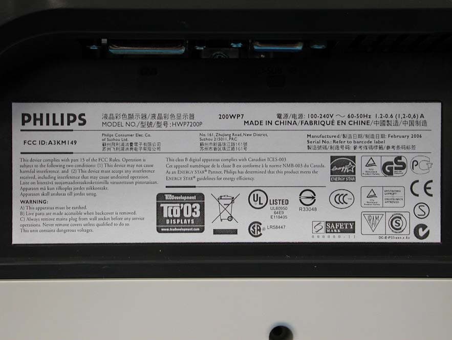
A3KM149
Mar 16, 200620� LCD Monitor
Equipment Class
JBP - Part 15 Class B Computing Device Peripheral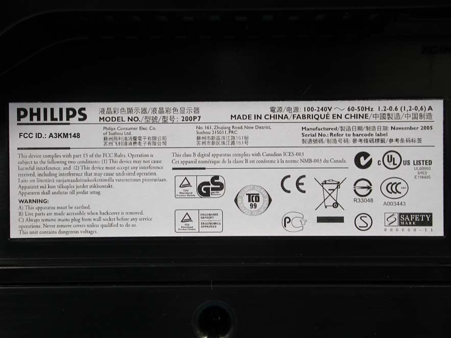
A3KM148
Dec 15, 200520
Equipment Class
JBP - Part 15 Class B Computing Device Peripheral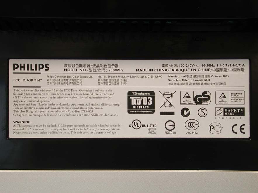
A3KM147
Nov 17, 2005LCD Monitor
Equipment Class
JBP - Part 15 Class B Computing Device Peripheral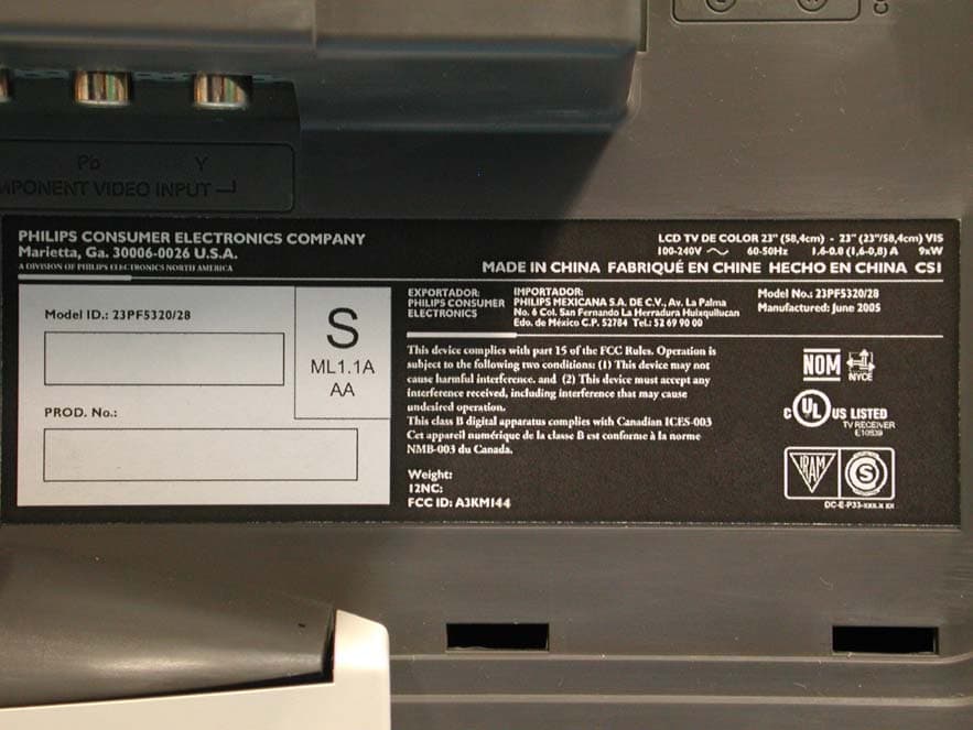
A3KM144
Jul 19, 2005LCD TV
Equipment Class
JBP - Part 15 Class B Computing Device Peripheral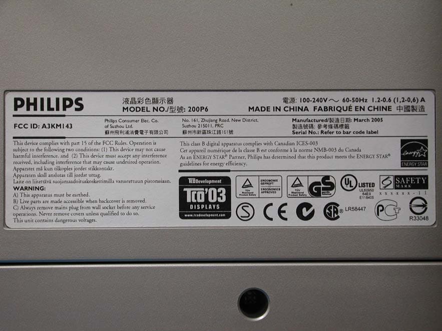
A3KM143
Apr 18, 2005Display Color Monitor
Equipment Class
JBP - Part 15 Class B Computing Device Peripheral