A3KM136LCD TV
Philips Electronics Industries (Taiwan) Ltd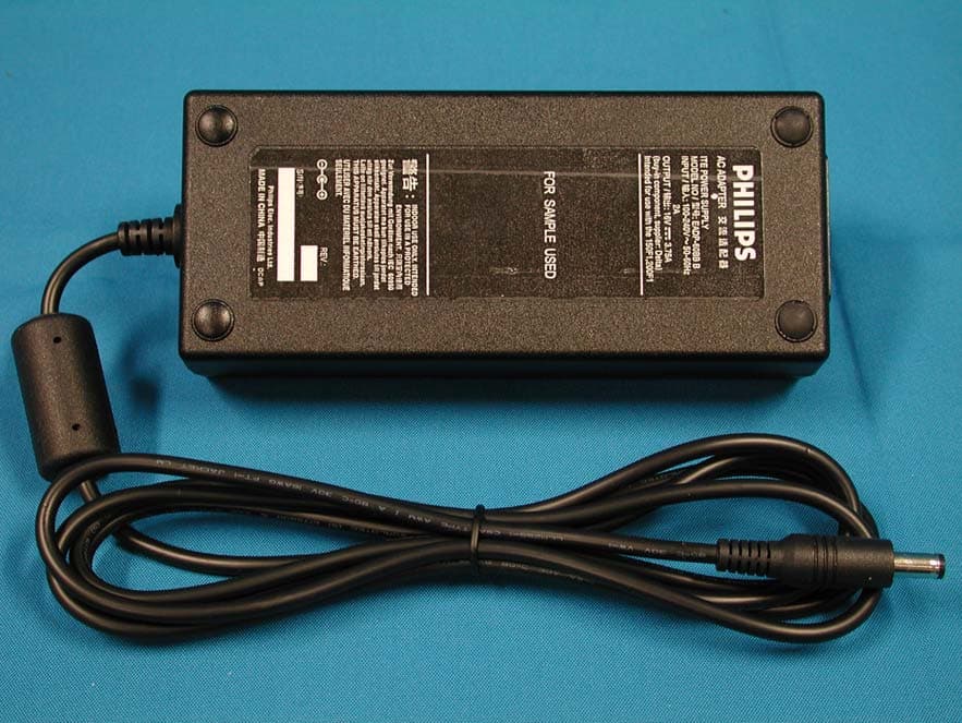
Click to zoom
Application Details
- Equipment Class
- JBP - Part 15 Class B Computing Device Peripheral
- Date of Grant
- Jan 12, 2005
- Application Purpose
- Original Equipment
- Date of Application
- Jan 12, 2005
- Equipment Note
- LCD TV
- Country
- Taiwan
Documents & Files
Document Text
Text extracted from the exhibit documents filed with the FCC. Open a document above to read the original.
Users Manual
NEED HELP?CALL US! MAGNAVOX REPRESENTATIVES ARE READY TO HELP YOU WITH ANY QUESTIONS ABOUT YOUR NEW PRODUCT. WE CAN GUIDE YOU THROUGH CONNECTIONS, FIRST-TIME SETUP, AND ANY OF THE FEATURES. WE WANT YOU TO START ENJOYING YOUR NEW PRODUCT RIGHT AWAY. CALL US BEFORE YOU CONSIDER RETURNING THE PRODUCT. 1-800-705-2000 OR VISIT US ON THE WEB AT WWW.MAGNAVOX.COM 15MF/20MF Series LCD TV Owner`s Manual Important! Return your Warranty Registration Card within 10 days. 3138 117 08021 Know these safety symbols This “bolt of lightning” indicates uninsulated material within your unit may cause an electrical shock. For the safety of everyone in your household, please do not remove product covering. The “exclamation point” calls attention to features for which you should read the enclosed literature closely to prevent operating and maintenance problems. WARNING: To reduce the risk of fire or electric shock, this apparatus should not be exposed to rain or moisture and objects filled with liquids, such as vases, should not be placed on this apparatus. CAUTION: To prevent electric shock, match wide blade of plug to wide slot, fully insert. ATTENTION: Pour éviter les choc électriques, introduire la lame la plus large de la fiche dans la borne correspondante de la prise et pousser jusqu’au fond. For Customer Use Enter below the Serial No. which is located on the rear of the cabinet. Retain this information for future reference. Model No._______________________ Serial No. _______________________ 2 RETURN YOUR PRODUCT REGISTRATION CARD TODAY TO GET THE VERY MOST FROM YOUR PURCHASE. Registering your model with MAGNAVOX makes you eligible for all of the valuable benefits listed below, so don’t miss out. Complete and return your Product Registration Card at once to ensure: *Proof of Purchase Returning the enclosed card guarantees that your date of purchase will be on file, so no additional paperwork will be required from you to obtain warranty service. *Product Safety Notification By registering your product, you’ll receive notification - directly from the manufacturer - in the rare case of a product recall or safety defect. *Additional Benefits of Product Ownership Registering your product guaran- tees that you’ll receive all of the privileges to which you’re entitled, including special money-saving offers. Congratulations on your purchase, and welcome to the “family!” Dear MAGNAVOX product owner: Thank you for your confidence in MAGNAVOX. You’ve selected one of the best-built, best-backed products available today. We’ll do everything in our power to keep you happy with your purchase for many years to come. As a member of the MAGNAVOX “family,” you’re entitled to protection by one of the most comprehensive warranties and outstanding service networks in the industry. What’s more, your purchase guarantees you’ll receive all the information and special offers for which you qualify, plus easy access to accessories from our convenient home shopping network. Most importantly, you can count on our uncompromising commitment to your total satisfaction. All of this is our way of saying welcome - and thanks for investing in a MAGNAVOX product. P.S. To get the most from your MAGNAVOX purchase, you must return your Warranty Registration Card within 10 days. So please mail it to us right now! Visit our World Wide Web Site at http://www.magnavox.com IMPORTANT SAFETY INSTRUCTIONS R EAD BEFORE OPERATING EQUIPMENT Read these instructions. Keep these instructions. Heed all warnings. Follow all instructions. Do not use this apparatus near water. Clean only with a dry cloth. Do not block any of the ventilation openings. Install in accordance with the manufacturers instructions. Do not install near any heat sources such as radiators, heat registers, stoves, or other apparatus (including amplifiers) that produce heat. Do not defeat the safety purpose of the polarized or grounding-type plug. A polarized plug has two blades with one wider than the other. A grounding type plug has two blades and third grounding prong. The wide blade or third prong are provided for your safety. When the provided plug does not fit into your outlet, consult an electrician for replacement of the obsolete outlet. Protect the power cord from being walked on or pinched particularly at plugs, convenience receptacles, and the point where they exit from the apparatus. Only use attachments/accessories specified by the manufacturer. Use only with a cart, stand, tripod, bracket, or table specified by the manufacturer, or sold with the apparatus. When a cart is used, use caution when moving the cart/apparatus combination to avoid injury from tip-over. Unplug this apparatus during lightning storms or when unused for long periods of time. Refer all servicing to qualified service personnel. Servicing is required when the apparatus has been damaged in any way, such as power-supply cord or plug is damaged, liquid has been spilled or objects have fallen into apparatus, the apparatus has been exposed to rain or moisture, does not operate normally, or has been dropped. This product may contain lead and mercury. Disposal of these materials may be regulated due to environmental considerations. For disposal or recycling information, please contact your local authorities or the Electronic Industries Alliance: www.eiae.org Damage Requiring Service - The appliance should be serviced by qualified service personnel when: A. The power supply cord or the plug has been damaged; B. Objects have fallen, or liquid has been spilled into the appliance; C. The appliance has been exposed to rain D. The appliance does not appear to operate normally or exhibits a marked change in performance; E. The appliance has been dropped, or the enclosure damaged. Tilt/Stability - All televisions must comply with recommended international global safety standards for tilt and stability properties of its cabinet design. • Do not compromise these design standards by applying excessive pull force to the front, …
Text truncated - open the document above for the full version.
Block Diagram
Exhibit 5 System block diagram SAA7119 TEXT SAA5360/1 1Mx16 MCU 128K ADVIDEO MST515X2 DDC 24C02 EEPROM24C32 SCL/SDA DDC_SDA/DDC_SCL (ISP) LVDS / TTL AD IF MM Tuner PC_input AV_CVBS_SC SC_R/G/B or YPbPr Y/C Tuner_CVBS TEXT FB/FR/FG 8Bits ITU656 YPbPr( HD ) MSP34X5 PC_AUD_in YPbPr_AUD_in CVBS_AUD_in SC_AUD_in 2 n d _IF SATPA3005D2 SC_AUD_OUT SPEAKER PANEL 1Mx1 MUX S S A A A A 7 7 1 1 1 1 9 9 + + M M S S T T AV_CVBS_RCA Exhibit 4 Brief Description of Circuit Functions 1. General Description This LCD-TV-F1 support PC analog input up to 800X600 60Hz mode for SVGA panel, and support TV (RF), YC, CVBS, and SCART. Also for Y Pb Pr signal input from SDTV to HDTV (480I, 480P, 720P, 1080i 60Hz and 576I, 576P, 720P, 1080I 50Hz). This LCD - TV use MST51502 as Scaler engine, which has embedded Analog D-sub, digital DVI decoder, scaling input signal to panel OSD mapping and simple 3D de-interlacer. The extra SDRAM is to accomplish video frame rate conversion and PIP function. The external CPU can be used to back light control, RC, keypad input, IIC I/O communication and. TV tuning control, sound control, and SAA7119A video decoder. Video decoder SAA7119 is used for TV video processing and convert it with CCIR 601/16bits or 656/8bits digital format and send to Scaler for de-interlace process, and also CC,V-chip data decode. One audio decoder MSP34XXG is used for TV sound processing, and output to post amplifier and SCART out. An option function in WE model “Telttext display”. Data decode is done by SAA5360, output RGB/FB is to video decoder input for text overlapping. In non-text model, this chip is N.C. 2. System block diagram Scaler choice: If the panel interface is TTL type: 20” use MST51502L. If the panel interface is LVDS type: 14”15”17” use MST51512L SAA7119 TEXT SAA5360 /1 1Mx16 MCU 128K AD VIDEO MST515X2 DDC 24C02 EEPROM 24C32 SCL/SDA DDC_SDA/ DDC_SCL (ISP) LVDS / TTL AD IF MM Tuner PC_input AV_CVBS_SC SC_R/G/B or YPbPr Y/C Tuner_CVBS TEXT FB/FR/FG 8Bits ITU656 YPbPr( HD ) MSP34X5 PC_AUD_in YPbPr_AUD_in CVBS_AUD_in SC_AUD_in 2 nd _IF SATPA 3005D2 SC_AUD_OUT SPEAKER PANEL 1Mx1 M U X S S A A A A 7 7 1 1 1 1 9 9 + + M M S S T T AV_CVBS_RCA 3. Function description: MM tuner is used to receive RF wave and output CVBS and 2nd IF signal. CVBS is to video decoder (SAA7119) for color process, 2nd IF is to sound decoder (MSP34x5) for audio process. The tuner control is via IIC ex. channel tuning. For different TV system, tuner and sound decoder have diversity as above. Standard TV input (Tuner, S-video, CVBS, SCART) is processed by SAA7119, But YPbPr, SDTV and HDTV(480i, 576i, 480p,576p,720p,1080i), is done by scaler MST51512L/502L ADC. But the signal is still link to SAA7119 if PIP (video in graph) function is requested. Then all YPbPr signal processed by SAA7119 could be the PIP video source. (* May use down sampling in HD0) MV protect is decoded by scaler. Video decoder SAA7119, is in charge of color decoding, could support PAL, NTSC and SECAM world wide system. Compare to SAA7118, SAA7119 improve some picture quality, like V-chip CC I2C read- back, LTI, CTI, skin tone correction(see task A), also the HD0 is supported, so if F1 need PIP function then the The Teltext function is for WE model, need a extra IC SAA5360. CVBS input, R/G/B, FB, out. Due to the SAA5360 request input signal 1Vrms and only one input channel, so the CVBS input source is from SAA7119 AOUT (CVBS out with 1Vrms). The R/G/B FB output into SAA7119 by AI22/AI32/AI42, and AI44 could overlay on any video source. Sound decoder MSP3415/45 is responsible to sound decode of tuner 2 nd IF. It has one 2nd IF, two selectable audio sources input. And one loudspeaker, one scart out. Due to the input port limitation, a MUX is added for AV source select( PC audio in is fix in SC1). If the post audio amplifier is gain fixed type then the volume adjust will be on MSP34x5. Scaler MST51502L/51512L besides scaling function, PIP, 3D de-interlacer, color enhance are major feature. Even de-interlacer is not so good but for static picture is enough to avoid image sticking. In America market, to avoid patent issue, two SDRAM is necessary for graph frame buffer. But in else region one SDRAM is enough. Of course, if no PC mode in spec, then one SDRAM for all model. The scaler structure limitation, the PIP source only from “video port”, 8 bits or 16 bits. The sub window /PIP size can enlarge to half screen. MCU, NT68F632AL, is 128K flash ROM inside. Power control, RC5 I/O, and key function all done by here, more detail function will description in chapter 4.later. All chip communication is by IIC (SDA/SCL), and ISP is via DDCIIC, but if PC mode un- supported, then a reserved 6pin connector is for same application.
External Photos
Page 1 of 11 Exhibit 7 Photographs Front View Rear View Page 2 of 11 Label Front View w/o Base Page 8 of 11 AC Adapter Assembly with Shielding Page 11 of 11 Power Cord and I/F Cables
ID Label/Location Info
Exhibit 2 FCC ID Label
Internal Photos
Page 3 of 11 Rear View w/o Back Cover Shielding Cover Page 4 of 11 Assembly w/o Shielding Cover PCB Layout Page 5 of 11 PCB Layout PCB Layout Page 6 of 11 PCB Layout Assembly w/o PCB Page 7 of 11 Plate LCD Panel Page 8 of 11 AC Adapter Assembly with Shielding Page 9 of 11 Assembly with Shielding Shielding Page 10 of 11 PCB Layout PCB Layout
Test Report
FCC ID. A3KM136 Page 1 of 31 Audix Corporation. Report No. EM-F930267 APPLICATION FOR CERTIFICATION On Behalf of Philips Electronics Industries (Taiwan) Ltd. LCD TV Model No.20MF605T/17 Brand : Philips Magnavox FCC ID: A3KM136 Prepared for : Philips Electronics Industries (Taiwan) Ltd. 5, Tze Chiang 1 Rd, Chungli Ind. Park, Chungli, Taoyuan Hsien, Taiwan, R.O.C. Prepared By : AUDIX Corporation Technical Division EMC Department No. 53-11, Tin-Fu Tsun, Lin-Kou, Taipei County, Taiwan, R.O.C. Tel: (02) 2609-9301, 2609-2133 Fax: (02) 2609-9303 File Number EM931466 Report Number EM-F930267 Date of Test Dec. 22 ~ 23, 2004 Date of Report Dec. 27, 2004 FCC ID. A3KM136 Page 2 of 31 Audix Corporation. Report No. EM-F930267 TABLE OF CONTENTS Description Page Test Report Certification........................................................................................................................3 1. GENERAL INFORMATION ...........................................................................................................4 1.1. Description of Device (EUT) .................................................................................................................... 4 1.2. Tested Supporting System Details ............................................................................................................ 5 1.3. Test Facility .............................................................................................................................................. 7 1.4. Measurement Uncertainty ......................................................................................................................... 7 2. CONDUCTED DISTURBANCE MEASUREMENT .....................................................................8 2.1. Test Equipment ......................................................................................................................................... 8 2.2. Block Diagram of Test Setup.................................................................................................................... 8 2.3. Conducted Powerline Emission Limit (§15.107, Class B) ....................................................................... 8 2.4. EUT’s Configuration during Compliance Measurement .......................................................................... 9 2.5. Operating Condition of EUT..................................................................................................................... 9 2.6. Test Procedure ........................................................................................................................................ 10 2.7. Line Conducted RF Voltage Measurement Results ................................................................................ 10 3. RADIATED DISTURBANCE MEASUREMENT .......................................................................17 3.1. Test Equipment ....................................................................................................................................... 17 3.2. Block Diagram of Test Setup.................................................................................................................. 17 3.3. Radiation Limit (§15.109/CISPR 22, Class B) ....................................................................................... 18 3.4. EUT’s Configuration during Compliance Measurement ........................................................................ 18 3.5. Operating Condition of EUT................................................................................................................... 18 3.6. Test Procedure ........................................................................................................................................ 18 3.7. Radiated Emission Measurement Results ............................................................................................... 19 4. DEVIATION TO TEST SPECIFICATIONS................................................................................26 5. PHOTOGRAPHS.............................................................................................................................27 5.1. Photos of Powerline Conducted Measurement .......................................................................................27 5.2. Photos of Radiated Measurement at Open Area Test Site ...................................................................... 29 FCC ID. A3KM136 Page 3 of 31 Audix Corporation. Report No. EM-F930267 TEST REPORT CERTIFICATION Applicant Philips Electronics Industries (Taiwan) Ltd. Manufacturer Philips Electronics Industries (Taiwan) Ltd. Factory Philips Consummer Electronics Co., of Suzhou Ltd. EUT Description LCD TV FCC ID A3KM136 (A) MODEL NO. 20MF605T/17 (B) SERIAL NO. TY0404732 (C) BRAND NAME Philips Magnavox (D) POWER SUPPLY 16VDC, 3.0A (E) TEST VOLTAGE AC 120V/60Hz (Via Power Adapter) Measurement Standards and Methods Used : FCC CFR 47 Part15 / Jul. 2004 and CISPR 22/1997 and ANSI C63.4-2003 The device described above was tested by AUDIX Corporation to determine the maximum emission levels emanating from the device. The maximum emission levels were compared to the FCC Part 15 Subpart B with the provisions of section 15.107 (a) and 15.109 (g) Class B limits both conducted and radiated emission. The measurement results are contained in this test report and AUDIX Corporation is assumed full responsibility for the accuracy and completeness of these measurements. Also, this report shows that the EUT to be technically compliance with the FCC official limits. This report applies to above tested sample only. This report shall not be reproduced in part without written approval of AUDIX Corporation. Date of Test : Dec. 22 ~ 23, 2004 Prepared by : (May Chen/Assistant) Test Engineer : (Ben Cheng/Section Manager) Approved & Authorized Signer : (Leon Liu/Senior Manager) FCC ID. A3KM136 Page 4 of 31 Audix Corporation. Report No. EM-F930267 1. GENERAL INFOR…
Text truncated - open the document above for the full version.
Test Setup Photos
FCC ID. A3KM136 Page 27 of 31 Audix Corporation. Report No. EM-F930267 5. PHOTOGRAPHS 5.1. Photos of Powerline Conducted Measurement Test Mode: D-Sub Input (“H” Pattern) FRONT VIEW OF CONDUCTED MEASUREMENT BACK VIEW OF CONDUCTED MEASUREMENT FCC ID. A3KM136 Page 28 of 31 Audix Corporation. Report No. EM-F930267 Test Mode: D-Sub + RF Input (PIP Mode, “H” Pattern + “Color Bar” image) FRONT VIEW OF CONDUCTED MEASUREMENT BACK VIEW OF CONDUCTED MEASUREMENT FCC ID. A3KM136 Page 29 of 31 Audix Corporation. Report No. EM-F930267 5.2. Photos of Radiated Measurement at Open Area Test Site Test Mode: D-Sub Input (“H” Pattern) FRONT VIEW OF RADIATED MEASUREMENT BACK VIEW OF RADIATED MEASUREMENT FCC ID. A3KM136 Page 30 of 31 Audix Corporation. Report No. EM-F930267 Test Mode: D-Sub + RF Input (PIP Mode, “H” Pattern + “Color Bar” image) FRONT VIEW OF RADIATED MEASUREMENT BACK VIEW OF RADIATED MEASUREMENT FCC ID. A3KM136 Page 31 of 31 Audix Corporation. Report No. EM-F930267 Test Mode: D-Sub Input, 800*600/60Hz, 38kHz; H Pattern SETUP WITH MAXIMUM DETECTED EMMISSION AT HORIZONTAL POLARIZATION SETUP WITH MAXIMUM DETECTED EMMISSION AT VERTICAL POLARIZATION
Contact Information
Applicant
Ronnie Yang(Manager, Safety/DEV)
Test Firm
Audix Technology CorporationJeff Chen
Technical Specifications
| # | Rule Parts | Frequency Range | Power Output |
|---|---|---|---|
| 1 | 15B | - | - |
Other Applications from Philips Electronics Industries (Taiwan) Ltd
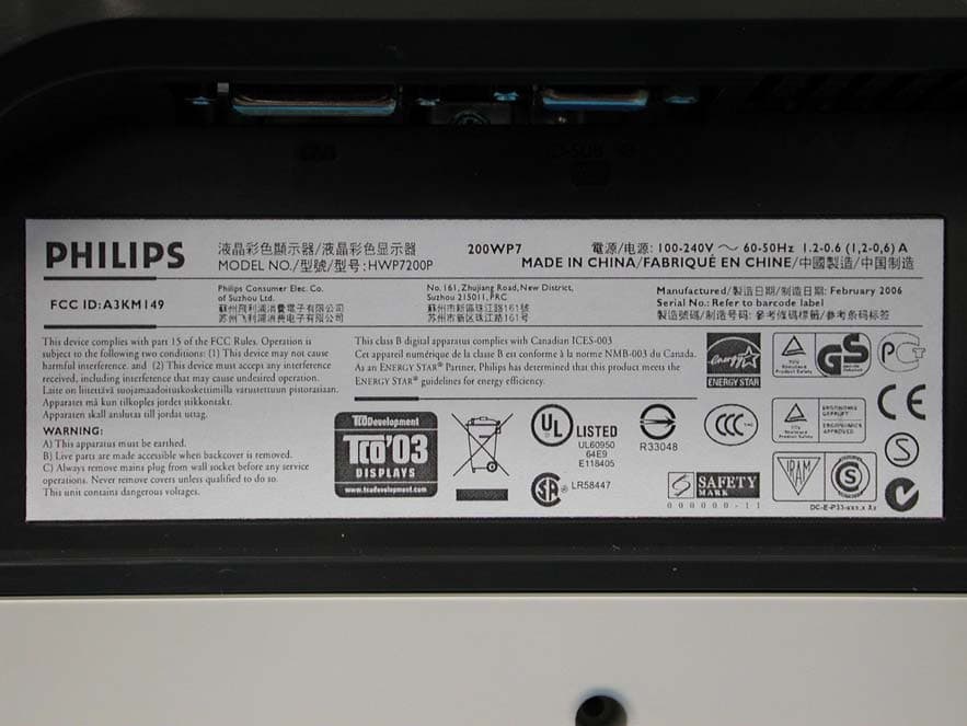
A3KM149
Mar 16, 200620� LCD Monitor
Equipment Class
JBP - Part 15 Class B Computing Device Peripheral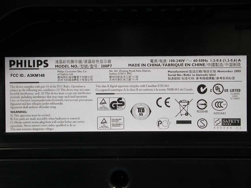
A3KM148
Dec 15, 200520
Equipment Class
JBP - Part 15 Class B Computing Device Peripheral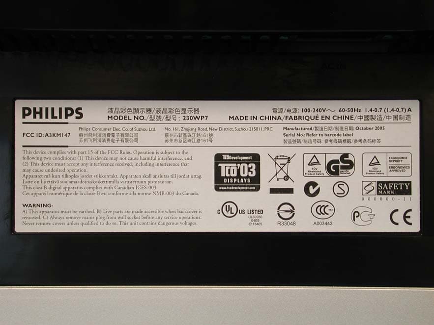
A3KM147
Nov 17, 2005LCD Monitor
Equipment Class
JBP - Part 15 Class B Computing Device Peripheral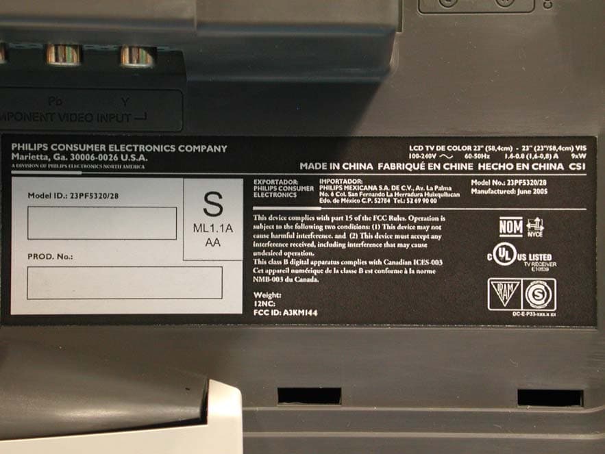
A3KM144
Jul 19, 2005LCD TV
Equipment Class
JBP - Part 15 Class B Computing Device Peripheral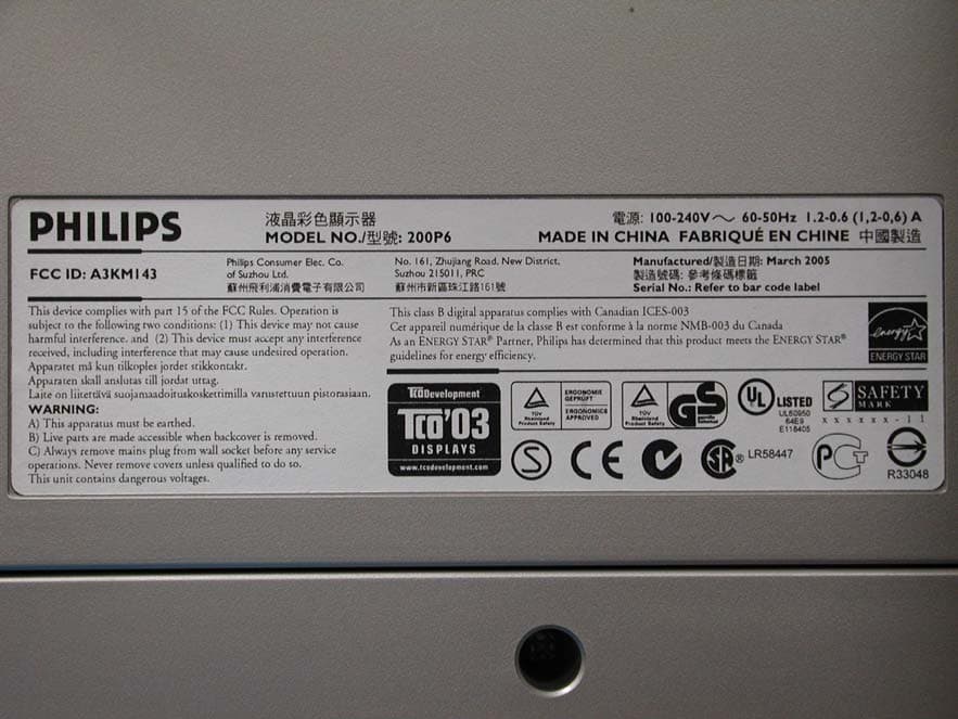
A3KM143
Apr 18, 2005Display Color Monitor
Equipment Class
JBP - Part 15 Class B Computing Device Peripheral