A3KM150DM10PCF WLAN Module
Philips Electronics Industries (Taiwan) Ltd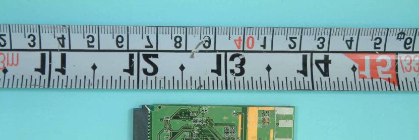
Click to zoom
Application Details
- Equipment Class
- DTS - Digital Transmission System
- Date of Grant
- Feb 18, 2003
- Application Purpose
- Original Equipment
- Date of Application
- Feb 18, 2003
- Equipment Note
- CF WLAN Module
- Frequency Range
- 2412.00000000 - 2462.00000000
- Country
- Taiwan
Documents & Files
Document Text
Text extracted from the exhibit documents filed with the FCC. Open a document above to read the original.
Cover Letter(s)
Philips Electronics Industries(Taiwan)Ltd. Feb. 12, 2003 Federal Communications Commission Authorization and Evaluation Division FCC IDA3KM150DM10P Confidentiality Request Pursuant to Sections 0..457 and 0.459 of the Commission’s Rules, the Applicant Hereby requests confidential treatment of information accomparrting this Application As outlined below 1. schematics and block diagram 2. OEM manual The schematics and block diagram contain trade secrets and proprietary information not customarily released to the public. The public disclosure of these matters might be harmful to the Applicant and provide unjustified benefits to its competitors. The OEM manual contains technical information and will be provided only to the OEM integrators. End-users will not be provided with this information. The Applicant understands that pursuant to Rule 0.457, disclosure of this Application and all accompanying documentation will not be made before the date of the Grant for this application Sincerely, Eddy Liu/Product Manager Applicant:Eddy Liu ADDRESS:5 Tze Chiang 1 Road , Chungli Industrial Park P.P.BOX123, Chungli, Taoyuan, Taiwan, R.O.C TEL:886-3-4549590 FAX:886-3-4549584
Cover Letter(s)
FEDERAL COMMUNICATIONS COMMISSION Authorization and Evaluation Division 7435 Oakland Mills Road Columbia, MD 21046 U.S.A. To whom it may concern: I, hereby, declare that the following EMI suppression components on the EUT, FCC ID: A3KM150DM10P, will be added or layout on the mass production products. 1. A ferrite core is added on the antenna cable. PHILIPS ELECTRONICS INDUSTRIES (TAIWAN) LTD Product Manger: Eddy Liu Date: February,11 th ,2003
Cover Letter(s)
FCC ID: A3KM150DM10P Date: Feb, 10, 2003 Modular Approval Request Letter To whom it may concern, The EUT would like to be authorized as modular approval. The following table shows the EUT meets eight criteria of FCC Public Notice DA 00-1407. Yours sincerely, Requirement of Public Notice DA00-1407 Reference to 1. The modular transmitter must have its own RF shielding. The module has its own RF shielding. Please see external photo, page 1. 2. The modular transmitter must have buffered modulation/ data inputs. The modular has buffered data inputs, it is integrated in chip ISL 3873. Please see schematic diagram. 3. The modular transmitter must have its own power supply regulation. All power lines derived from the host device are regulated before energizing other circuits internal to the EUT. Please see schematic diagram 4. The modular transmitter must comply with the antenna requirements of Section 15.203 and 15.204(c). The EUT meets the FCC antenna requirements. Please see external , page 1. 5. The modular transmitter must be tested in a stand-alone configuration, i.e., the module must not be inside another device during testing. The EUT was tested in a stand-alone configuration via a PCMCIA extender. Please see section 2.4 of test report. 6. The modular transmitter must be labeled with its own FCC ID number, and, if the FCC ID is not visible when the module is installed inside another device, then the outside of the device into which the module is installed must also display a label referring to the enclosed module. The label position of EUT is clearly indicated. Please see the label drawing and label location files.. 7. The modular transmitter must comply with any specific rule or operating requirements applicable to the transmitter and the manufacturer must provide adequate instructions along with the module to explain any such requirements. A copy of these instructions must be included in the application for equipment authorization. The EUT is compliant with all applicable FCC rules. Detail instructions are given in the Users Manual. Please see user manual. 8. The modular transmitter must comply with any applicable RF exposure requirements. For example, FCC Rules in Sections 2.1091, 2.1093 and specific Sections of Part 15, including 15.319(i), 15.407(f), 15.253(f) and 15.255(g), require that Unlicensed PCS, UNII and millimeter wave devices perform routine environmental evaluation for RF Exposure to demonstrate compliance. In addition, spread spectrum transmitters operating under Section 15.247 are required to address RF Exposure compliance in accordance with Section 15.247(b)(4). The EUT comply with applicable RF exposure requirements. Please see section 5.9 of test report..
External Photos
FCC ID : A3KM150DM10P FRONT SIDE OF EUT Number 1 FCC ID : A3KM150DM10P REAR SIDE OF EUT Number 2
ID Label/Location Info
P M KATTY CHANG FCC ID: A3KM150DM10P 5 T ze Chiang 1 Road., Chungli Industrial Park, P.O. Box 123 Chungli, Taoyuan, Taiwan Philips Elec. Industries Ltd. MODEL NO. : 150DM10P WARNING: A) This apparatus must be earthed. B) Live parts are made accessible when backcover is removed. C) Always remove mains plug from wall socket before any service operations. Never remove covers unless qualified to do so. This unit contains dangerous voltages. 0470 ! MADE IN TAIWAN 19V-3. 16A XXXX E211285 XXXXX M75-1WJ03-000 CAUTION: DO NOT expose to fire orextreme high temperature. DO NOT short external circuit. RISK OF EXPLOSION IF BATTERY IS REPLACED BY AN INCORRECT TYPE. DISPOSE OF USED BATTERIES ACCORDING TO THE INSTRUCTIONS. MODEL NO. :SG3BA1 11.1V 3.6Ah Rechargeable smart battery must be recycled or disposed of properly. Read instructions in user guide before using this battery. FINAL ASSEMBLY IN TAIWAN M75-1WJ01-000 D-PH3KBT6+X01 CAUTION: DO NOT expose to fire orextreme high temperature. DO NOT short external circuit. RISK OF EXPLOSION IF BATTERY IS REPLACED BY AN INCORRECT TYPE. DISPOSE OF USED BATTERIES ACCORDING TO THE INSTRUCTIONS. MODEL NO. :SG3BA1 11.1V 3.6Ah Rechargeable smart battery must be recycled or disposed of properly. Read instructions in user guide before using this battery. FINAL ASSEMBLY IN TAIWAN D-PH3KBT6+X03 M75-1WJ04-000 MODEL NO. : PH3XXX WARNING: A) This apparatus must be earthed. B) Live parts are made accessible when backcover is removed. C) Always remove mains plug from wall socket before any service operations. Never remove covers unless qualified to do so. This unit contains dangerous voltages. MADE IN TAIWAN 19V-3. 16A XXXX E211285 XXXXX Value Through PCMCIA in 3A From Anywhere to Anyplace at Anytime
ID Label/Location Info
FCC ID : A3KM150DM10P FCC ID LOCATION
Internal Photos
FCC ID : A3KM150DM10P Number 1 Mechanical Construction FCC ID : A3KM150DM10P Number 2 Mechanical Construction
Operational Description
XI815 circuit description MAC and B.B: ISL3873 that is a CPU control and process between PCMCIA interface and BaseBand. ISL3873( U3 ) integrated Baseband process is part of the PRISM chip. The ISL3873 directly interfaces with IF QMODEM(HFA3783). Adding Intersil’s RF/IF converter ISL3685) and power amplifier (ISL3984). Protocols and PHY support are implemented in firmware thus, supporting customization. The ISL3873 have on board A/Ds and D/A for analog I and Q inputs and outputs, for which the HFA3783. DBPSK and DQPSK, with data scrambling capability, are available along with CCK to provide a variety of data rates. Both Receive and Transmit AGC functions with 7-bit AGC control obtain maximum performance in the analog portion of the transciver. IF QMODEM HFA3783: The HFA3783 is a highly integrated and fully SiGe baseband converter for half duplex wireless application. It has a integrated AGC receive IF amplifier and variety Transmit amplifier. The receive and Transmit paths share a common differential path. A pair of 2 nd order antialiasing filtrs with an integrated DC offset cancellation architecture is include in the AGC chain for threshold comparison. Up and down conversion are perform by doubly balanced mixer for I/Q IF processing. RF/IF converter and synthesizer ISL3685: The ISL3685 include a receive chain feature LNA and down-converter mixer. For tX chain have an up-converter mixer and driver amplifier. Also have RF synthesizer to lock 2.1GHz that convert IF (374MHz) 2.4GHz. RF power amplifier ISL3984: The ISL3984 is a 2.4GHz RF power amplifier that power the signal from ISL3685 transmit chain. ISL3984 include a power amplifier and a power detector to make a Automatic level control RF power. RF filter FL4 MDR742F and FL2 MDR741F: Pass the RF signal and reject spurious from Transmit mixer that ISL3685 polling out. RF switch U13 As179: Control RF signal to Receive and transmit chain by MAC ISL3873.
Test Report
FCC TEST REPORT Report No. : F2D1903 SPORTON International Inc. TEL : 886-2-2696-2468 FAX : 886-2-2696-2255 FCC TEST REPORT for 47 CFR, Part 15, Subpart C Equipment : CF WLAN Module Model No. : XI-815 FCC ID : A3KM150DM10P Filing Type : Certification Applicant : Philips Electronics Industries (Taiwan) Ltd. 5 Tze Chiang 1 Rd, Chungli Ind. Park PO Box 123, Chungli † The test result refers exclusively to the test presented test model / sample. † Without written approval of SPORTON International Inc., the test report shall not be reproduced except in full. † Certificate or Test Report must not be used by the applicant to claim the product in this test report endorsement by NVLAP or any agency of U.S. government. SPORTON International Inc. 6F, No.106, Sec. 1, Hsin Tai Wu Rd., Hsi Chih, Taipei Hsien, Taiwan, R.O.C. FCC TEST REPORT Report No. : F2D1903 SPORTON International Inc. FCC ID : A3KM150DM10P TEL : 886-2-2696-2468 Page No. : i FAX : 886-2-2696-2255 Issued Date : Feb. 10, 2003 Table of Contents History of this test report.........................................................................................................ii CERTIFICATE OF COMPLIANCE..............................................................................................................1 1. General Description of Equipment under Test......................................................................................2 1.1. Applicant.......................................................................................................................................................................................2 1.2. Manufacturer.................................................................................................................................................................................2 1.3. Basic Description of Equipment under Test..................................................................................................................................2 1.4. Feature of Equipment under Test.................................................................................................................................................3 2. Test Configuration of Equipment under Test........................................................................................5 2.1. Test Manner..................................................................................................................................................................................5 2.2. Description of Test System...........................................................................................................................................................5 2.3. Connection Diagram of Test System.............................................................................................................................................7 2.4. Test Setup photographs................................................................................................................................................................8 3. Operation of Equipment under Test......................................................................................................9 4. General Information of Test................................................................................................................10 4.1. Test Voltage................................................................................................................................................................................10 4.2. Standard for Methods of Measurement.......................................................................................................................................10 4.3. Test in Compliance with..............................................................................................................................................................10 4.4. Frequency Range Investigated...................................................................................................................................................10 4.5. Test Distance..............................................................................................................................................................................10 5. Report of Measurements and Examinations.......................................................................................11 5.1. List of Measurements and Examinations....................................................................................................................................11 5.2. 6dB Bandwidth............................................................................................................................................................................12 5.3. Peak Output Power.....................................................................................................................................................................16 5.4. Power Spectral Density...............................................................................................................................................................17 5.5. Test of Conducted Emission.......................................................................................................................................................21 5.6. Test of Radiated Emission..........................................................................................................................................................25 5.7. Band Edges Measurement..........................................................................................................................................................34 5.8. Antenna Requirements...............................................................................................................................................................37 5.9. RF Exposure.........................................................................…
Text truncated - open the document above for the full version.
Test Setup Photos
FCC TEST REPORT Report No. : F2D1903 SPORTON International Inc. FCC ID : A3KM150DM10P TEL : 886-2-2696-2468 Page No. : 1 of 3 FAX : 886-2-2696-2255 Issued Date : Feb. 10, 2003 1.1. Photographs of Conducted Emission Test Configuration n The photographs show the configuration that generates the maximum emission. FRONT VIEW REAR VIEW FCC TEST REPORT Report No. : F2D1903 SPORTON International Inc. FCC ID : A3KM150DM10P TEL : 886-2-2696-2468 Page No. : 2 of 3 FAX : 886-2-2696-2255 Issued Date : Feb. 10, 2003 SIDE VIEW FCC TEST REPORT Report No. : F2D1903 SPORTON International Inc. FCC ID : A3KM150DM10P TEL : 886-2-2696-2468 Page No. : 3 of 3 FAX : 886-2-2696-2255 Issued Date : Feb. 10, 2003 1.2. Photographs of Radiated Emission Test Configuration n The photographs show the configuration that generates the maximum emission. FRONT VIEW REAR VIEW
Contact Information
Applicant
Ronnie Yang(Manager, Safety/DEV)
Test Firm
SPORTON International IncKathy Lin
Technical Specifications
| # | Rule Parts | Frequency Range | Power Output |
|---|---|---|---|
| 1 | 15C | 2.41 GHz - 2.46 GHz | 33.00 mW |
Other Applications from Philips Electronics Industries (Taiwan) Ltd
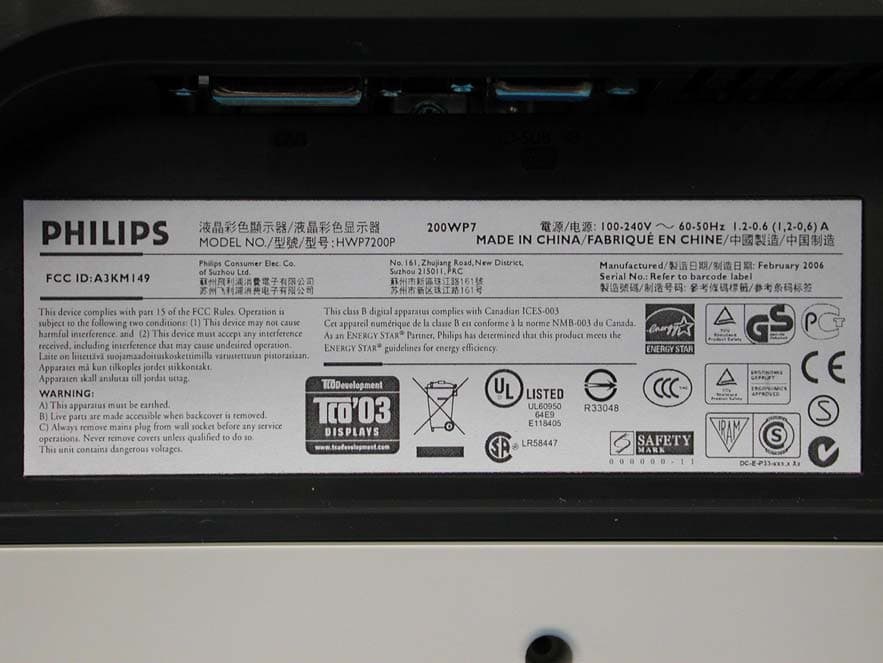
A3KM149
Mar 16, 200620� LCD Monitor
Equipment Class
JBP - Part 15 Class B Computing Device Peripheral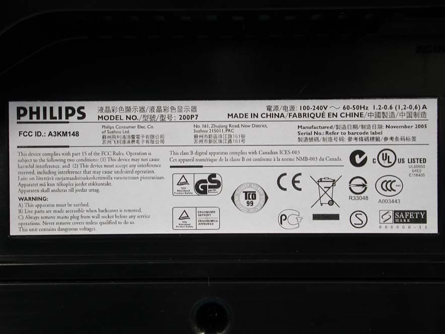
A3KM148
Dec 15, 200520
Equipment Class
JBP - Part 15 Class B Computing Device Peripheral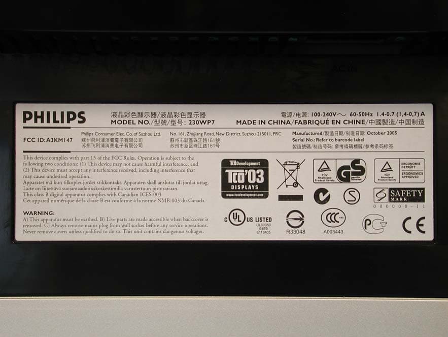
A3KM147
Nov 17, 2005LCD Monitor
Equipment Class
JBP - Part 15 Class B Computing Device Peripheral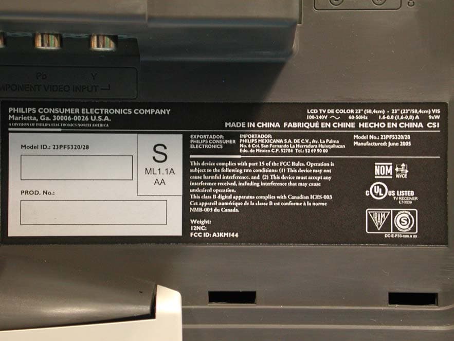
A3KM144
Jul 19, 2005LCD TV
Equipment Class
JBP - Part 15 Class B Computing Device Peripheral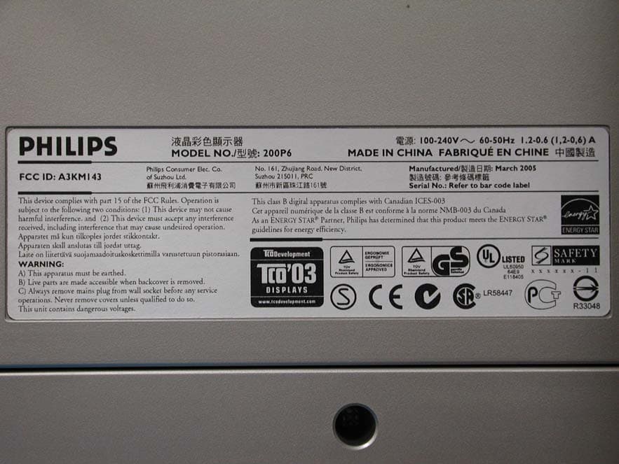
A3KM143
Apr 18, 2005Display Color Monitor
Equipment Class
JBP - Part 15 Class B Computing Device Peripheral