A7RM2B0ADVD/Video Cassette Recorder
ORION ELECTRIC CO., LTD.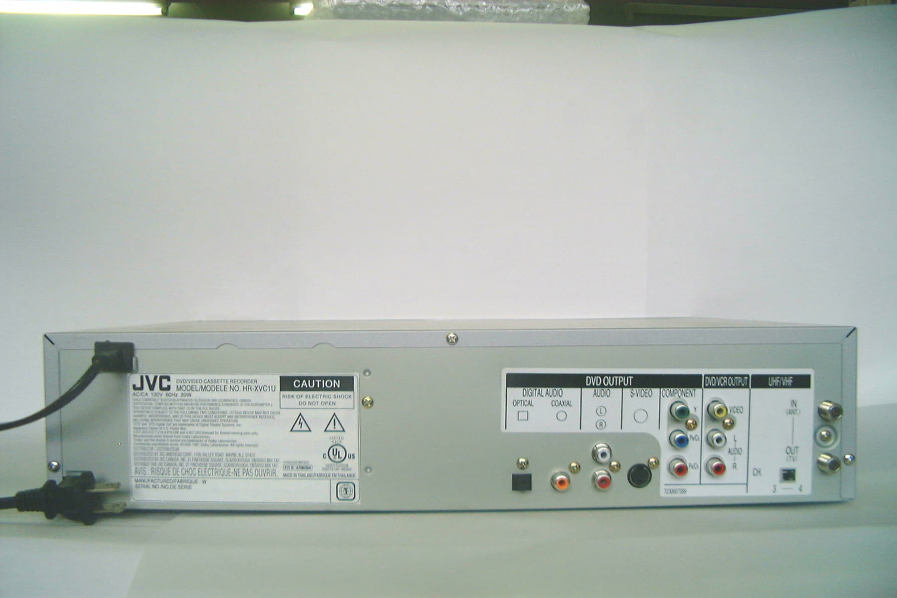
Click to zoom
Application Details
- Equipment Class
- HID - Part 15 TV Interface Device
- Date of Grant
- Apr 23, 2002
- Application Purpose
- Original Equipment
- Date of Application
- Apr 23, 2002
- Equipment Note
- DVD/Video Cassette Recorder
- Frequency Range
- 67.25000000 - 71.75000000
- Company
- ORION ELECTRIC CO., LTD.
- Country
- Japan
Documents & Files
Document Text
Text extracted from the exhibit documents filed with the FCC. Open a document above to read the original.
Users Manual
Serial Number IMPORTANT NOTE TO THE CUSTOMER: In the space below, enter the serial number for your television (located on the rear of the television cabinet). Staple your sales receipt or invoice to the inside cover of this guide. Keep this user's guide in a convenient place for future reference. Keep the carton and original packaging for future use. For model: HR-XVC1U DVD/VIDEO CASSETTE RECORDER USER’S GUIDE ¤ T V / V C R C H + TV VCR DVD POWER DVD MENU MARKERRETURN OPEN/ CLOSE DISPLAYA.TRK C.RESET ZERO RETURN SUB TITLE ANGLE SEARCH MODE SP/EP PLAY MODE ZOOM TITLE REPEAT A-B TV POWER INPUT TV VOL 0 TIMER TV/VCR R E W PLAY F F R E C STOP P A U S E SKIP /INDEX SKIP /INDEX T V / V C R C H — SETSET ENTER/ SELECT SET UP MENU CANCEL O S D A.MONITOR S L O W S K IP S E A R C H VCR/DVD/TV 2 WARNING:TO PREVENT FIRE OR SHOCK HAZARD, DO NOT EXPOSE THIS APPLIANCE TO RAIN OR MOISTURE. CAUTION:TO PREVENT ELECTRIC SHOCK DO NOT USE THIS POLARIZED PLUG WITH AN EXTENSION CORD, RECEPTACLE OR OTHER OUTLET UNLESS THE BLADES CAN BE FULLY INSERTED TO PREVENT BLADE EXPOSURE. CAUTION: THIS DIGITAL VIDEO PLAYER EMPLOYS A LASER SYSTEM. TO ENSURE PROPER USE OF THIS PRODUCT, PLEASE READ THIS USER'S GUIDE CAREFULLY AND RETAIN FOR FUTURE REFERENCE. SHOULD THE UNIT REQUIRE MAINTENANCE, CONTACT A JVC AUTHORIZED SERVICE CENTER. USE OF CONTROLS, ADJUSTMENTS OR THE PERFORMANCE OF PROCEDURES OTHER THAN THOSE SPECIFIED HEREIN MAY RESULT IN HAZARDOUS RADIATION EXPOSURE. TO PREVENT DIRECT EXPOSURE TO LASER BEAM, DO NOT TRY TO OPEN THE ENCLOSURE. VISIBLE LASER RADIATION MAY BE PRESENT WHEN THE ENCLOSURE IS OPENED. DO NOT STARE INTO BEAM. Location of the required Marking The rating sheet and the safety caution are on the rear of the unit. CERTIFICATION: COMPLIES WITH FDA RADIATION PERFORMANCE STANDARDS, 21 CFR SUBCHAPTER J. RISK OF ELECTRIC SHOCK DO NOT OPEN CAUTION The lightning flash with arrowhead symbol, within an equilateral triangle is intended to alert the user to the presence of uninsulated dangerous voltage within the product's enclosure that may be of sufficient mag- nitude to constitute a risk of electric shock. The exclamation point within an equilateral triangle is intended to alert the user to the presence of important operating and maintenance (servicing) instructions in the literature accompa- nying the appliance. CAUTION: TO REDUCE THE RISK OF ELECTRIC SHOCK, DO NOT REMOVE COVER (OR BACK). NO USER-SERVICEABLE PARTS INSIDE. REFER SERVICING TO QUALIFIED SERVICE PERSONNEL. WARNING:This equipment has been tested and found to comply with the limits for a Class B digital device, pursuant to Part 15 of the FCC Rules. These limits are designed to provide reasonable protection against harmful interference in a residential installation. This equipment generates, uses and can radiate radio frequency energy and, if not installed and used in accordance with the instructions, may cause harmful interference to radio communications. However, there is no guarantee that interference will not occur in a particular installation. If this equipment does cause harmful interference to radio or television reception, which can be determined by turning the equipment off and on, the user is encouraged to try to correct the interference by one or more of the following measures: - Reorient or relocate the receiving antenna. - Increase the separation between the equipment and receiver. - Connect the equipment into an outlet on a circuit different from that to which the receiver is connected. - Consult the dealer or an experienced radio/TV technician for help. CAUTION:Changes or modifications not expressly approved by the partly responsible for compliance with the FCC Rules could void the user's authority to operate this equipment. 3 CH. IN OUT ANT. DIGITAL AUDIOAUDIOS-VIDEOCOMPONENT DVD OUTPUT L R VIDEO OPTICALCOAXIAL AUDIO L R 4 ( ) TV ( ) Y PB/CB PR/CR 3 Important safeguards 1. READ INSTRUCTIONS All the safety and operating instructions should be read before the unit is operated. 2. RETAIN INSTRUCTIONS The safety and operating instructions should be retained for future reference. 3. HEED WARNINGS All warnings on the unit and in the operating instructions should be adhered to. 4. FOLLOW INSTRUCTIONS All operating and use instructions should be followed. 5. CLEANING Unplug this unit from the wall outlet before cleaning. Do not use liquid cleaners or aerosol cleaners. Use a damp cloth for cleaning the exterior cabinet only. 6. ATTACHMENTS The manufacturer of this unit does not make any recommendations for attachments, as they may cause hazards. 7. WATER AND MOISTURE Do not use this unit near water. For example, near a bathtub, washbowl, kitchen sink, laundry tub, in a wet basement, or near a swimming pool. 8. ACCESSORIES Do not place this unit on an unstable cart, stand, tripod, bracket, or table. The unit may fall, causing serious injury, and serious damage to the unit. 8A.An appliance and cart combination should be moved with care. Quick stops, excessive force, and uneven surfaces may cause the appliance and cart combination to overturn. 9. VENTILATION Slots and openings in the cabinet back or bottom are provided for ventilation, and to ensure reliable operation of the unit, and to protect it from overheating. These openings must not be blocked or covered. The openings should never be blocked by placing the unit on a bed, sofa, rug, or other similar surface. This unit should never be placed near or over a radiator or heat source. This unit should not be placed in a built-in installations such as a bookcase or rack unless proper ventilation is provided or the manufacturer’s instructions have been adhered to. 10. POWER SOURCES This unit should be operated only from the type of power source indicated on the rating plate. If you are not sure of the type of power supply to your home, consult your appliance dealer or local power company. For units intended to operate from battery power, or other sources, refer to the operating instructions. 11. G…
Text truncated - open the document above for the full version.
Cover Letter(s)
A-PEX International Co., Ltd. Newstage Yokohama Blug. 1F 1-1-32 Shin-urashima-cho Kanagawa-ku Yokohama-shi Kanagawa-ken Japan April 24, 2002 FCC ID A7RM2B0A 1) We have sent modified file of block diagram A and B. 2) We have sent modified file of Form 731. 3) We confirm that there were no modifications necessary. 4) The remote control, which is in the photographs, is only for the reference. 5) The distance of 80cm can be taken. 6) It is because a margin beyond 20dB is fully taken over 2000MHz. 7) The page 52.1, 52.2, 56.1 56.2 were added to the data. Will you confirm it? Would you please check to ATCB web file. Ryo Kojima
Cover Letter(s)
American Telecommunications Certification Body Inc. 6731 Whittier Ave, McLean, VA 22101 April 22, 2002 RE: Orion Electric Co., Ltd. FCC ID: A7RM2BOA After a review of the submitted information, I have a few comments on the above referenced Application. 1) Please provide a block diagram that includes the frequencies as specified by CFR 2.1033(a)(5). It appears that schematics were provided in place of the block diagrams. 2) The 731 Form lists the FCC ID as A7RA7RM2BOA. It appears that the Grantee code is listed twice since the labeling exibit only shows A7RM2BOA. Please confirm the correct ID number correct the affected exhibits. 3) A modification letter was included but contained only XXXXXXXX. Please confirm that there were no modifications necessary. 4) FYI, this application only covers the Host unit. The remote control is not covered by this application even though it is pictured in the test photographs. 5) The LISN used for conducted emissions does not appear to be 80 cm away from the EUT as specified by ANSI C63.4. Please comment. 6) Please explain the rational for testing to 2000 MHz. Many tuners contain LO frequencies in excess of 1.8 GHz. Also, the device may tune to channels 125 Cable and 69 TV which would suggest testing to at least 5 GHz. See 15.33.(b)(1). Please comment 7) Data shown on page 51 & 55 of the report shows Average data above 1 GHz. However, the peak emissions coming from the EUT must also a limit that is 20 dB above the average limit (15.35(b)). Data or justification as to the peak to average ratio have not been provided. Data should be taken using a 1 MHz RBW and 1 MHz Video Bandwidth. Timothy R. Johnson Examining Engineer mailto: [email protected] The items indicated above must be submitted before processing can continue on the above referenced application. Failure to provide the requested information may result in application termination. Correspondence should be considered part of the permanent submission and may be viewed from the Internet after a Grant of Equipment Authorization is issued. Please do not respond to this correspondence using the email reply button. In order for your response to be processed expeditiously, you must submit your documents through the AmericanTCB.com website. Also, please note that partial responses increase processing time and should not be submitted. Any questions about the content of this correspondence should be directed to the sender.
ID Label/Location Info
ATTACHMENT J-1 FCC ID: A7RM2B0A FCC IDENTIFIER (♣2.926) LABELING REQUIREMENT(♣15.19) --- Labeling BACK VIEW
Operational Description
CIRCUIT DESCRIPTION 1/2 This device is combined a DVD player with a Video cassette recorder and operates with an AC commercial power supply.(AC120V, 60Hz) This device includes TV interface Device, Television Broadcast receiver ,and Digital device of product category defined by FCC. The external connectors are equipped with Front Audio (L/R)/Video Input, RF input/Output, Rear Audio (L/R) Video Output, Component Out, S-VHS Output, DVD Audio Output, Optical Digital Audio Out, Coaxial Digital Audio out and so on. The circuit is composed by Power Supply Block , VCR Block, and DVD Block, if divided roughly. The explanation is as follows and the details are referred to Block Diagram. Power Supply Block: Use the switching regulator circuit and provide the power supply to each cirucuit. VCR Block: The circuit of this block is composed by Tuner/IF/Modulator, Luminance and Chrominance/Audio/CCD/Head Amp, System/Timer/Servo, HIFI Demodulator, Audio/Video Switching, Sround, Mixer, Motor Drive and so on RF Modulator output is output in US 3ch or 4ch and Emission frequency is as Follows: Emission Frequency; US 3ch Video carrier: 61.25MHz Audio carrier: 65.75MHz US 4ch Video carrier: 67.25MHz Audio carrier: 71.75MHz The oscillating frequencies that is used this block are the follows: 10MHz----VCR System Control IC Clock 14.318MHz--- VCR System Control IC Clock 32.768KHz--- VCR System Control IC Clock 3.579545MHz---Luminance and Chrominance IC Clock DVD Block: The block part of DVD comprises of a read control device of a disk, a signal processing device, a decoder part and a control unit. Each device is in charge of serial processing from reading to indication of a signal. A reading device of a disk comprises of a motor part spinning a disk and a 2/2 laser part reading data from the disk. A signal processing device converts a laser pulse read by a disk to the digital data which a decoder can process The decoder part develop compressed digital data and output in a personal computer , television, a stereo system and etc. as a picture , a voice and other data.. A control unit controls the operation from a wireless remote controller and front panel and the order input form a software and controls a decoder and other mechanism The oscllating frequencies that is used this block are the follows: 108MHz--- SD-RAM Clock(MPCLK) 27MHz--- MPEG Master Clock(GCLK) 16.9344MHz--- DVD DSP Clock 18.4327MHz--- Audio Master Clock(AMCLK) 12.5MHz---DVD System Control Clock 3.072MHz---Audio bit Clock(ABCLK) 48kHz---Audio L/R Clock(LRCLK)
Test Report
Test report No. : 22IE0009-KT-1 Page : 2 of 92 Date of issue : April 17, 2002 A-pex International Co., Ltd. Kanto Office EMC Laboratory. Newstage Yokohama Bldg.1F 1-1-32 Shin-Urashima-cho, Kanagawa-ku, Yokohama-shi, Kanagawa 221-0031, JAPAN Telephone : +81 45 450 1515 Facsimile: +81 45 450 1534 Contents Page Section 1 : Client information 3 Section 2 : Equipment under test (E.U.T.) 3 Section 3 : Test specification, methods & procedures 5 Section 4 : Operation of E.U.T. during tests 6 Section 5 : Summary of test results 7 Section 6 : Test instruments 9 Section 7 : Conducted interference 10 Section 8 : Radiated emission 13 Section 9 : Antenna terminal voltage 16 Section 10 : RF output level / spurious emission 17 Section 11 : Antenna transfer switch 18 Section 11 : Picture sensitivity 19 Section 12 : Noise figure 20 Appendix 1 : Photographs of test set up 21 Appendix 2 : Data of EMI tests 29 Test report No. : 22IE0009-KT-1 Page : 3 of 92 Date of issue : April 17, 2002 A-pex International Co., Ltd. Kanto Office EMC Laboratory. Newstage Yokohama Bldg.1F 1-1-32 Shin-Urashima-cho, Kanagawa-ku, Yokohama-shi, Kanagawa 221-0031, JAPAN Telephone : +81 45 450 1515 Facsimile: +81 45 450 1534 Section 1 : Client information Company name : ORION ELECTRIC CO., LTD. Brand name : JVC Address : 41-1 Iehisa-cho, Takefu-shi, Fukui 915-8555 JAPAN Telephone number : +81-778-23-0019 Facsimile number : +81-778-23-7799 Contact person : Hiroshi Tsujimoto Section manager Engineering headquarters Administration section Section 2 : Equipment under test (E.U.T.) 2.1 Identification of E.U.T. Type of equipment : DVD / VCR Model number : HR-XVC1U Rating : AC 120 V / 60 Hz Manufacturer : 1. WORLD ELECTRIC (THAILAND) LTD. 236 Moo 2 Nongchark, Banbung, Chonburi 20170, Thailand 2. KORAT DENKI LTD. 149 Moo 10 Thombol Chokchai, Amphur Chokchai, Nakhonratchasima 30190, Thailand 3. ORION AMERICA, INC. Hwy 41 North, Orion Place, Princeton, Indiana 47670, U.S.A Receipt Date of Sample : April 08, 2002 Condition of EUT : Production Prototype Test report No. : 22IE0009-KT-1 Page : 4 of 92 Date of issue : April 17, 2002 A-pex International Co., Ltd. Kanto Office EMC Laboratory. Newstage Yokohama Bldg.1F 1-1-32 Shin-Urashima-cho, Kanagawa-ku, Yokohama-shi, Kanagawa 221-0031, JAPAN Telephone : +81 45 450 1515 Facsimile: +81 45 450 1534 2.2 Product description ORION ELECTRIC CO., LTD., Model: HR-XVC1U (referred to as the EUT in this report) is a DVD/VCR. The EUT specifications is as follows. Tuner type : Quartz PLL frequency synthesized I / F : 45.75 MHz (Picture), 41.25 MHz (Sound) Receiving channel : VHF 2 – 13 ch / UHF 14 – 69 ch / CATV 1 – 125 ch Antenna input : 75 ohm Video signal : NTSC color Power source : AC 120 V / 60 Hz, 20 W I / O terminal (Video) : RCA in 1Vp-p 75 ohm, RCA out 1 Vp-p 75 ohm I / O terminal (Audio) : RCA in –8 dB 50 k ohm, RCA out –8 dB 1 k ohm 2.3 Product description There are similar apparatus for the EUT as follows. HR-XVC1U/M HR-XVC1UC HR-XVC1UC/M Test report No. : 22IE0009-KT-1 Page : 5 of 92 Date of issue : April 17, 2002 A-pex International Co., Ltd. Kanto Office EMC Laboratory. Newstage Yokohama Bldg.1F 1-1-32 Shin-Urashima-cho, Kanagawa-ku, Yokohama-shi, Kanagawa 221-0031, JAPAN Telephone : +81 45 450 1515 Facsimile: +81 45 450 1534 Section 3 : Test specification, methods & procedures 3.1 Test specification Test specification : FCC Part 15 Subpart B Title : FCC 47 CFR Part15 Radio Frequency Device Subpart B Unintentional Radiators (Subpart C Intentional Radiators) 3.2 Methods & procedures No. Item Test procedure Limits Remarks 1 Conducted interference ANSI C63.4:1992 IEEE 213:1987 IEEE 187:1990 250 uV LISN 2 Radiated emission ANSI C63.4:1992 IEEE 213:1987 IEEE 187:1990 30–88 MH: 100 uV/m 88–216 MHz: 150 uV/m 216–960 MHz: 200 uV/m above 960 MHz: 500 uV/m 3 m 3 Antenna terminal voltage ANSI C63.4:1992 IEEE 213:1987 IEEE 187:1990 2 nW (at 75 ohm) – RF output level Video signal: 3000 uV Aural signal: 671 uV – 4 Spurious emission ANSI C63.4:1992 IEEE 213:1987 IEEE 187:1990 94.8 uV – 5 Transfer switch ANSI C63.4:1992 IEEE 213:1987 IEEE 187:1990 9.5 dB – 6 Picture sensitivity ANSI C63.4:1992 IEEE 213:1987 IEEE 187:1990 8 dB – 7 Noise figure FCC/OET MP:2:1986 14 dB – 3.3 Additions or deviations to standard No addition, deviation nor exclusion have been made from standards. Test report No. : 22IE0009-KT-1 Page : 6 of 92 Date of issue : April 17, 2002 A-pex International Co., Ltd. Kanto Office EMC Laboratory. Newstage Yokohama Bldg.1F 1-1-32 Shin-Urashima-cho, Kanagawa-ku, Yokohama-shi, Kanagawa 221-0031, JAPAN Telephone : +81 45 450 1515 Facsimile: +81 45 450 1534 Section 4 : Operation of E.U.T. during tests 4.1 Operating modes The EUT exercise program used during testing was designed exercise the various system components in a manner similar to typical use. The sequence in used : * Receive mode (0 dBmV input / 25 dBmV input) * AV input mode (1 Vp-p input / 5 Vp-p input) * VCR playback mode * DVD play mode Operation : The EUT tested above operation mode (Using a video tape with a typical TV signal recorded on it, if necessary.) Justification : The system was configured in typical fashion (as a customer would normally use it) for testing. 4.2 Configuration and peripherals Front View A B * Cabling was taken into consideration and test data was taken under worse case conditions. Top View A AC 120 V / 60 Hz 75 ohm terminator 1 2 75 ohm terminator 1 k ohm terminator 75 ohm terminator 50 k ohm terminator * Cabling was taken into consideration and test data was taken under worse case conditions. Description of EUT and support equipment Sign Item Model number Serial number Manufacturer A DVD/VCR HR-XVC1U – ORION ELECTRIC CO., LTD. B Remote Controller – – ORION ELECTRIC CO., LTD. Meshed column are represented List of cable used No. Item Length (m) Shielding Manufacturer 1 AC power cable 1.8 Unshielded – 2 RF output cable 1.0 Shielded Supplies accessory Test report No. : 22IE0009-KT-1 Page : 7 of 92 Date of issue : April…
Text truncated - open the document above for the full version.
Test Report
Test report No. : 22IE0009-KT-1 Page: 29 of 92 Date of issue: April 17, 2002 A-pex International Co., Ltd. Kanto Office EMC Laboratory. Newstage Yokohama Bldg.1F 1-1-32 Shin-Urashima-cho, Kanagawa-ku, Yokohama-shi, Kanagawa 221-0031, JAPAN Telephone : +81 45 450 1515 Facsimile: +81 45 450 1534 Appendix 2 : Data of EMI tests This section contains the following data. Page 30 to Page 41 :Conducted interference Page 42 to Page 62 :Radiated emission Page 63 to Page 64:Antenna terminal voltage Page 65 to Page 82 :RF output level / spurious emission Page 83 to Page 90 :Antenna transfer switch Page 91 :Picture sensitivity Page 92 :Noise figure
Test Setup Photos
Test report No. : 22IE0009-KT-1 Page: 21 of 92 Date of issue: April 17, 2002 A-pex International Co., Ltd. Kanto Office EMC Laboratory. Newstage Yokohama Bldg.1F 1-1-32 Shin-Urashima-cho, Kanagawa-ku, Yokohama-shi, Kanagawa 221-0031, JAPAN Telephone : +81 45 450 1515 Facsimile: +81 45 450 1534 Appendix 1 : Photographs of test set up This section contains the following photographs. Page 22 : Test set up of conducted interference Page 23 : Test set up of radiated emission Page 24 : Test set up of antenna terminal voltage Page 25 : Test set up of RF output level / spurious emission Page 26 : Test set up of antenna transfer switch Page 27 : Test set up of picture sensitivity Page 28 : Test set up of noise figure Test report No. : 22IE0009-KT-1 Page: 22 of 92 Date of issue: April 17, 2002 A-pex International Co., Ltd. Kanto Office EMC Laboratory. Newstage Yokohama Bldg.1F 1-1-32 Shin-Urashima-cho, Kanagawa-ku, Yokohama-shi, Kanagawa 221-0031, JAPAN Telephone : +81 45 450 1515 Facsimile: +81 45 450 1534 Conducted interference Test report No. : 22IE0009-KT-1 Page: 23 of 92 Date of issue: April 17, 2002 A-pex International Co., Ltd. Kanto Office EMC Laboratory. Newstage Yokohama Bldg.1F 1-1-32 Shin-Urashima-cho, Kanagawa-ku, Yokohama-shi, Kanagawa 221-0031, JAPAN Telephone : +81 45 450 1515 Facsimile: +81 45 450 1534 Radiated emission Test report No. : 22IE0009-KT-1 Page: 24 of 92 Date of issue: April 17, 2002 A-pex International Co., Ltd. Kanto Office EMC Laboratory. Newstage Yokohama Bldg.1F 1-1-32 Shin-Urashima-cho, Kanagawa-ku, Yokohama-shi, Kanagawa 221-0031, JAPAN Telephone : +81 45 450 1515 Facsimile: +81 45 450 1534 Antenna terminal voltage Test report No. : 22IE0009-KT-1 Page: 25 of 92 Date of issue: April 17, 2002 A-pex International Co., Ltd. Kanto Office EMC Laboratory. Newstage Yokohama Bldg.1F 1-1-32 Shin-Urashima-cho, Kanagawa-ku, Yokohama-shi, Kanagawa 221-0031, JAPAN Telephone : +81 45 450 1515 Facsimile: +81 45 450 1534 RF output level / spurious emission Test report No. : 22IE0009-KT-1 Page: 26 of 92 Date of issue: April 17, 2002 A-pex International Co., Ltd. Kanto Office EMC Laboratory. Newstage Yokohama Bldg.1F 1-1-32 Shin-Urashima-cho, Kanagawa-ku, Yokohama-shi, Kanagawa 221-0031, JAPAN Telephone : +81 45 450 1515 Facsimile: +81 45 450 1534 Antenna transfer switch Test report No. : 22IE0009-KT-1 Page: 27 of 92 Date of issue: April 17, 2002 A-pex International Co., Ltd. Kanto Office EMC Laboratory. Newstage Yokohama Bldg.1F 1-1-32 Shin-Urashima-cho, Kanagawa-ku, Yokohama-shi, Kanagawa 221-0031, JAPAN Telephone : +81 45 450 1515 Facsimile: +81 45 450 1534 Picture sensitivity Test report No. : 22IE0009-KT-1 Page: 28 of 92 Date of issue: April 17, 2002 A-pex International Co., Ltd. Kanto Office EMC Laboratory. Newstage Yokohama Bldg.1F 1-1-32 Shin-Urashima-cho, Kanagawa-ku, Yokohama-shi, Kanagawa 221-0031, JAPAN Telephone : +81 45 450 1515 Facsimile: +81 45 450 1534 Noise figure
Contact Information
Applicant
Akira Kohori(General Manager)
Technical Contact
A-Pex International Co., Ltd.Yshiyuki Arakawa
[email protected]+81-45-450-1515
1-1-32 Shin-Urashima-cho · Yokohama-shi, Kanagawa-ken · Japan
Non-Technical Contact
A-Pex International Co., Ltd.Yshiyuki Arakawa
[email protected]+81-45-450-1515
Test Firm
UL Japan, Inc.Osamu Watatani
Technical Specifications
| # | Rule Parts | Frequency Range | Power Output |
|---|---|---|---|
| 2 | 15B | 67.25 MHz - 71.75 MHz | - |
Other Applications from ORION ELECTRIC CO., LTD.
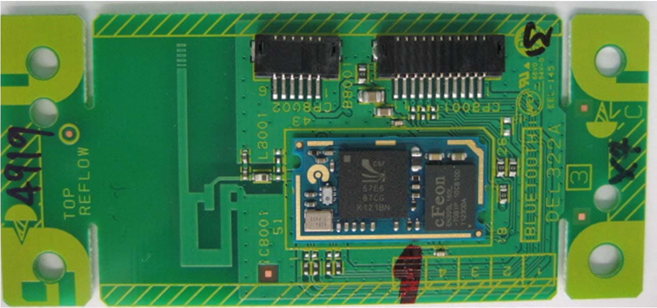
A7RM115A
Jul 16, 2012BLUETOOTH MODULE
Equipment Class
DSS - Part 15 Spread Spectrum Transmitter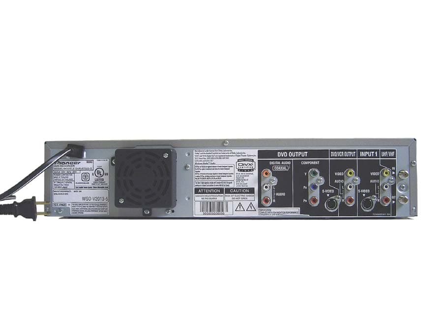
A7RM2J4B
May 23, 2006DVD / VCR TV Interface Device
Equipment Class
HID - Part 15 TV Interface Device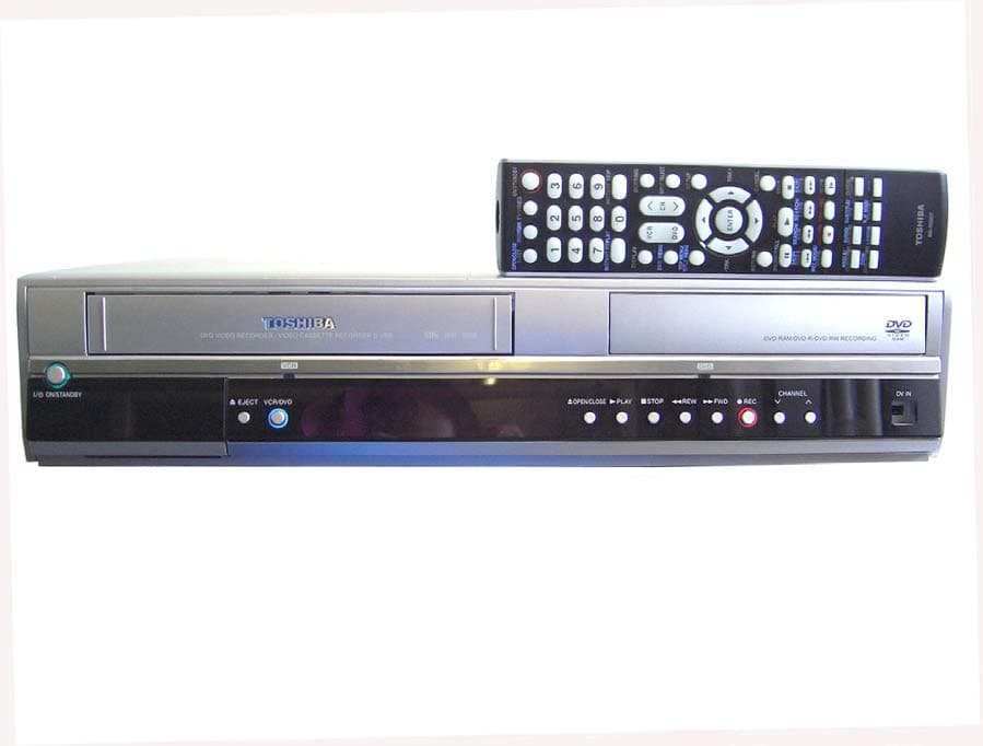
A7RM2J4A
Apr 11, 2006DVD / VCR TV Interface Device
Equipment Class
HID - Part 15 TV Interface Device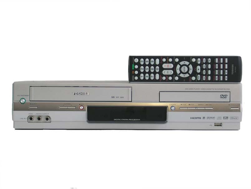
A7RM2I4A
Jan 26, 2006DVD / VCR TV Interface Device
Equipment Class
HID - Part 15 TV Interface Device
A7RM2I3A
Dec 06, 2005DVD/VCR TV Interface Device
Equipment Class
HID - Part 15 TV Interface Device