AAO1501892TRF Remote Control Transmitter
RadioShack Corporation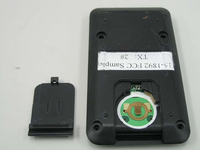
Click to zoom
Application Details
- Equipment Class
- DSC - Part 15 Security/Remote Control Transmitter
- Date of Grant
- Sep 12, 2005
- Application Purpose
- Original Equipment
- Date of Application
- Sep 12, 2005
- Equipment Note
- RF Remote Control Transmitter
- Frequency Range
- 433.92000000 - 433.92000000
- Company
- RadioShack Corporation
- Country
- United States
Documents & Files
Document Text
Text extracted from the exhibit documents filed with the FCC. Open a document above to read the original.
Users Manual
Your remote control is powered with a button-cell battery (included), to install the battery: 1. Press and push open the battery compartment cover. 2. Insert the CR2032 battery with positive polarity (+) facing up into the remote control then replace the cover. battery notes • Keep button-cell away from small children. If swallowed, promptly see a doctor. Have the doctor call 202-625-3333 collect. • Do not open the battery; or dispose of it in a fire; or recharge; or insert backwards . It may explode or leak, causing personal injury. • Use only fresh batteries of the required size and recommended type. • If you do not plan to use your remote control for a week or more, remove the batteries. Batteries can leak chemicals that can damage electronic parts. Please read this user’s guide before installing, setting up and using your new product www.radioshack.com installing batteries indoor VHF/UHF/HDTV antenna remote control 75 Ohm coaxial cable with gold plated connectors power adapter 1 button-cell battery user’s guide what’s included Microprocessor-Controlled Antenna Rotating Control – Allows you to rotate the antenna in 12 distinct positions only in a few seconds, either clockwise or counterclockwise for best UHF reception. 100 Channel Memories - Allows you to select up to 100 channels (0-99) and the corresponding antenna position stored for that channel. Built-in Amplifier Gain Control – Allows you to amplify weak signal. other features Thank you for purchasing the Indoor VHF/UHF/ HDTV Antenna with RF remote control from RadioShack. Your antenna is perfect for improving TV reception. You can retrieve stored channel position with the RF remote control by simply recalling one of the channel memories. Your antenna will automatically move to the direction you programmed for best reception. For VHF TV Channels 2-6 and FM radio: • Fully extend the telescopic antenna. For VHF TV Channels 7-13: • Retract the antenna to the appropriate length and move to an angle that produces the best reception adjusting your antenna 15-1892 indoor VHF/UHF/HDTV antenna with RF remote control To select a second video source, such as cable TV, a video game, or satellite dish signal, slide “AUX/ TV” switch to “AUX”. selecting another source battery compartment cover AUX/TV switch Perfect for improving TV reception, this indoor antenna boosts the best received signals to your TV, so you can enjoy the best picture. You can also use this antenna to improve FM radio reception installing your antenna 1. Place the antenna on or near your TV set. 2. Connect the antenna’s TV output cable to your TV’s or VCR’s input terminal. 3. Connect a second video source, if available, to the AUX terminal using the 75 ohm coaxial cable/connector. 4. Connect the supplied AC adapter’s barrel plug into the DC jack on the back of the indoor antenna, and connect the AC adapter’s other end to a standard AC outlet. CAUTION You must use an adapter that supplies 12V DC and delivers at least 350 mA. Its center tip must be set to positive and its plug must fit this indoor antenna’s jack. The supplied adapter meets these specifications. Using an adapter that does not meet these specifications could damage the indoor antenna or the plug. installing the antenna DC 12V jack AC-DC adaptor Antennas ©2005. RadioShack Corporation. All rights reserved. RadioShack and RadioShack.com are trademarks used by RadioShack Corporation. 15-1892 08A05 Printed in China P/N:AO0239AAA1 Frequency Range ................................VHF(54-214MHz) .........................................................UHF (470-806MHz) Gain Control .........................22dB Min for Level 3 gain ..............................................18dB Min for Level 2 gain ..............................................13dB Min for Level 1 gain Power Supply ..........................................12V @ 350mA AUX to TV Insertion Loss .............VHF/UHF 3.0dB Max AUX/TV Isolation .............................VHF/UHF 30dB Min Front to Back Ratio ............................................8dB Min Weight ..................................................................1.04kg Base unit Dimensions (W x D x H) ..320x 320x 206 mm Remote Control Dimensions (WxDxH) ...........................................................48 x 86 x 10.7 mm Specifications are typical and individual units may vary. Specifcations are subject to change and improvement without notice. Actual product may very from the images found in this document. specifications Warning: Changes or modifications to this unit not expressly approved by the party responsible for compliance could void the user’s authority to operate the equipment. This equipment has been tested and found to comply with the limits for a Class B digital device, pursuant to Part 15 of the FCC Rules. These limits are designed to provide reasonable protection against harmful interference in a residential installation. This equipment generates, uses, and can radiate radio frequency energy and, if not installed and used in accordance with the instructions, may cause harmful interference to radio communications. However, there is no guarantee that interference will not occur in a particular installation. If this equipment does cause harmful interference to radio or television reception, which can be determined by turning the equipment off and on, the user is encouraged to try to correct the interference by one or more of the following measures: • Reorient or relocate the receiving antenna. • Increase the separation between the equipment and receiver. • Connect the equipment into an outlet on a circuit different from that to which the receiver is connected. Consult your local RadioShack store or an experienced radio/TV technician for help. If you cannot eliminate the interference, the FCC requires that you stop using your microphone system. Changes or modifications not expressly approved by RadioShack may cause interference and void the user’s authority to opera…
Text truncated - open the document above for the full version.
Block Diagram
Block Diagram FCC ID: AAO1501892T S3C9442/C9444/F9444/C9452/C9454/F9454PRODUCT OVERVIEW 1-1 1PRODUCT OVERVIEW SAM88RCRI PRODUCT FAMILY Samsung's SAM88RCRI family of 8-bit single-chip CMOS microcontrollers offers a fast and efficient CPU, a wide range of integrated peripherals, and various mask-programmable ROM sizes. A address/data bus architecture and a large number of bit-configurable I/O ports provide a flexible programming environment for applications with varied memory and I/O requirements. Timer/counters with selectable operating modes are included to support real-time operations. S3C9442/C9444/C9452/C9454 MICROCONTROLLER The S3C9442/C9444/C9452/C9454 single-chip 8-bit microcontroller is designed for useful A/D converter , SIO application field. The S3C9442/C9444/C9452/C9454 uses powerful SAM88RCRI CPU and S3C9442/C9444/C9452/C9454 architecture. The internal register file is logically expanded to increase the on- chip register space. The S3C9442/C9444/C9452/C9454 has 2K/4K bytes of on-chip program ROM and 208 bytes of RAM. The S3C9442/C9444/C9452/C9454 is a versatile general-purpose microcontroller that is ideal for use in a wide range of electronics applications requiring simple timer/counter, PWM. In addition, the S3C9442/C9444/C9452/C9454’s advanced CMOS technology provides for low power consumption and wide operating voltage range. Using the SAM88RCRI design approach, the following peripherals were integrated with the SAM88RCRI core: —Three configurable I/O ports (18 pins) —Four interrupt sources with one vector and one interrupt level —One 8-bit timer/counter with time interval mode —Analog to digital converter with nine input channels and 10-bit resolution —One 8-bit PWM output The S3C9442/C9444/C9452/C9454 microcontroller is ideal for use in a wide range of electronic applications requiring simple timer/counter, PWM, ADC. S3C9452/C9454 is available in a 20/16-pin DIP and a 20-pin SOP package. S3C9452/C9454 is available in a 8-pin and a 8-pin SOP package. MTP The S3F9444/F9454 is an MTP (Multi Time Programmable) version of the S3C9442/C9444/C9452/C9454 microcontroller. The S3F9444/F9454 has on-chip 4-Kbyte multi-time programmable flash ROM instead of masked ROM. The S3F9444/F9454 is fully compatible with the S3C9442/C9444/C9452/C9454, in function, in D.C. electrical characteristics and in pin configuration. PRODUCT OVERVIEWS3C9442/C9444/F9444/C9452/C9454/F9454 1-2 FEATURES CPU •SAM88RCRI CPU core •The SAM88RCRI core is low-end version of the current SAM87 core. Memory •2/4-Kbyte internal program memory •208-byte general purpose register area Instruction Set •41 instructions •The SAM88RCRI core provides all the SAM87 core instruction except the word-oriented instruction, multiplication, division, and some one-byte instruction. Instruction Execution Time •400 ns at 10 MHz f OSC (minimum) Interrupts •4 interrupt sources with one vector •One interrupt level General I/O •Three I/O ports (Max 18 pins) •Bit programmable ports 8-bit High-speed PWM •8-bit PWM 1-ch (Max: 156 kHz) •6-bit base + 2-bit extension Built-in reset Circuit •Low voltage detector for safe reset Timer/Counters •One 8-bit basic timer for watchdog function •One 8-bit timer/counter with time interval modes A/D Converter •Nine analog input pins •10-bit conversion resolution Oscillation Frequency •1 MHz to 10 MHz external crystal oscillator •Maximum 10 MHz CPU clock •Internal RC: 3.2 MHz (typ.), 0.5 MHz (typ.) in V DD = 5 V Operating Temperature Range •– 40 ° C to + 85 ° C Operating Voltage Range •2.0 V (LVR Level) to 5.5 V Smart Option Package Types •S3C9452/C9454: –20-DIP-300A –20-SOP-375 –16-DIP-300A •S3C9442/C9444 –8-DIP-300 –8-SOP-225 S3C9442/C9444/F9444/C9452/C9454/F9454PRODUCT OVERVIEW 1-3 BLOCK DIAGRAM 88RCRI SAMRI CPU Port I/O and Interrupt Control 2 KB ROM 4 KB ROM 208 Byte Register file Timer 0 ADC PWM XIN XOUT OSC Basic Timer ADC0-ADC8 P0.6/PWM Port 0 Port 2 Port 1 P0.0/ADC0/INT0 P0.1/ADC1/INT1 P0.2/ADC2 P0.7/ADC7 ... P1.0 P1.1 P1.2 P2.0/T0 P2.1 P2.6 ... NOTE:P1.2 is used as input only Figure 1-1. Block Diagram
External Photos
INTERTEK TESTING SERVICE Report No.: 0511937 FCC ID: AAO1501892T Equipment Photographs Model : 15-1892 (External) INTERTEK TESTING SERVICE Report No.: 0511937 FCC ID: AAO1501892T Equipment Photographs Model : 15-1892 (External)
ID Label/Location Info
ART NO. REVECN NO. MODLE ZONE DESCRIPTION DRAFTDATE A PART NO. DWG. NO. PART NAME DEST APPROVED CHECKED DRAFT OR A/W PLS RETURN IMMEDIATELY AFT FILMED SCALE 15-1892 USA Rating Label AL0906AAA1 F09239A L01892P02A Merry 1:1 generated label a/w Merry4/12/05 DATE 4/12/05 Size: 30 x 13 mm TANDY RADIOSHACK LIMITED A Division of RadioShack Corporation ® Remote rating label Date Code label B Change the description Merry4/26/05 CAT. NO. 15-1892 INDOOR HDTV ANTENNA WITH RF REMOTE CONTROL (UHF RECEPTION ONLY) CUSTOM MFD. IN CHINA FOR RADIOSHACK CORP., FT. WORTH, TX 76102 FCC ID:AAO1501892TPOWER:CR2032 x 1
Internal Photos
INTERTEK TESTING SERVICE Report No.: 0511937 FCC ID: AAO1501892T Equipment Photographs Model : 15-1892 (Internal) INTERTEK TESTING SERVICE Report No.: 0511937 FCC ID: AAO1501892T Equipment Photographs Model : 15-1892 (Internal) INTERTEK TESTING SERVICE Report No.: 0511937 FCC ID: AAO1501892T Equipment Photographs Model : 15-1892 (Internal) INTERTEK TESTING SERVICE Report No.: 0511937 FCC ID: AAO1501892T Equipment Photographs Model : 15-1892 (Internal)
Operational Description
FCC ID: AAO1501892T 15-1892 Technical Description 15-1892 is an UHF remote control TV receiver, which can be divided into a few parts: Remote Control Brief Description of each section: The whole circuitry operates with a CR2032 battery. The remote control consisted of a S3C9454 MCU and an amplifier Q10. The data is being generated by the MCU, then directly modulate onto the 433.92MHz carrier(X2 resonator) and at last amplified by Q10 before sending out. FCC ID: AAO1501892T Entering Remote Control Test Mode Please follow the procedure below to use test mode: 1. Diagram 1. Holding the gain “+” and “-“ button. 2. Diagram 2. While holding the two keys, insert the CR2032 battery. 3. Close the battery door and the 433.92MHz carrier is in continuous transmitting mode.
Test Report
• The test results reported in this test report shall refer only to the sample actually tested and shall not refer or be deemed to refer to bulk from which such a sample may be said to have been obtained. • This report shall not be reproduced except in full without prior authorization from Intertek Testing Services Hong Kong Limited • For Terms And Conditions of the services, it can be provided upon request. • The evaluation data of the report will be kept for 3 years from the date of issuance. Intertek Testing Services Hong Kong Ltd. 2/F., Garment Centre, 576 Castle Peak Road, Kowloon, Hong Kong. Tel: (852) 2173 8888 Fax: (852) 2785 5487 Website: www.hk.intertek-etlsemko.com Tandy Electronics (China) Ltd. Application For Certification (FCC ID: AAO1501892T) Transmitter 0511937 TC/el September 05, 2005 INTERTEK TESTING SERVICES FCC ID: AAO1501892T i LIST OF EXHIBITS INTRODUCTION EXHIBIT 1: General Description EXHIBIT 2 : System Test Configuration EXHIBIT 3: Emission Results EXHIBIT 4: Equipment Photographs EXHIBIT 5: Product Labelling EXHIBIT 6: Technical Specifications EXHIBIT 7: Instruction Manual EXHIBIT 8: Miscellaneous Information INTERTEK TESTING SERVICES FCC ID: AAO1501892T ii MEASUREMENT / TECHNICAL REPORT Tandy Electronics (China) Ltd. − MODEL: RadioShack 15-1892 FCC ID: AAO1501892T September 05, 2005 This report concerns (check one:) Original Grant X Class II Change Equipment Type: Low Power Transmitter (example: computer, printer, modem, etc.) Deferred grant requested per 47 CFR 0.457(d)(1)(ii)? Yes No X If yes, defer until: date Company Name agrees to notify the Commission by: date of the intended date of announcement of the product so that the grant can be issued on that date. Transition Rules Request per 15.37? Yes No X If no, assumed Part 15, Subpart C for intentional radiator − the new 47 CFR [10-01-04 Edition] provision. Report prepared by: Billy Chow Intertek Testing Services 2/F., Garment Center, 576 Castle Peak Road, Kowloon, Hong Kong. Phone: 852-2173-8491 Fax: 852-2371-0914 INTERTEK TESTING SERVICES FCC ID: AAO1501892T iii Table of Contents 1.0 General Description ..........................................................................................2 1.1 Product Description.....................................................................................2 1.2 Related Submittal(s) Grants .......................................................................2 1.3 Test Methodology .......................................................................................3 1.4 Test Facility .................................................................................................3 2.0 System Test Configuration...............................................................................5 2.1 Justification .................................................................................................5 2.2 EUT Exercising Software ............................................................................5 2.3 Special Accessories....................................................................................5 2.4 Equipment Modification ..............................................................................6 2.5 Measurement Uncertainty...........................................................................6 2.6 Support Equipment List and Description ....................................................6 3.0 Emission Results...............................................................................................8 3.1 Field Strength Calculation...........................................................................9 3.2 Radiated Emission Configuration Photograph .........................................11 3.3 Radiated Emission Data ...........................................................................12 4.0 Equipment Photographs .................................................................................15 5.0 Product Labelling ............................................................................................17 6.0 Technical Specifications .................................................................................19 7.0 Instruction Manual ...........................................................................................21 8.0 Miscellaneous Information .............................................................................23 8.1 Measured Bandwidth ................................................................................24 8.2 Discussion of Pulse Desensitization .........................................................25 8.3 Calculation of Average Factor ..................................................................26 8.4 Emissions Test Procedures ......................................................................27 INTERTEK TESTING SERVICES FCC ID: AAO1501892T iv List of attached file Exhibit Type File Description Filename Test Report Test Report report.pdf Operation Description Technical Description descri.pdf Test Setup Photo Radiated Emission radiated photos.pdf Test Report Bandwidth Plot bw.pdf External Photo External Photo external photos.pdf Internal Photo Internal Photo internal photos.pdf Block Diagram Block Diagram block.pdf Schematics Circuit Diagram circuit.pdf ID Label / Location Label Artwork and Location label.pdf User Manual User Manual manual.pdf Test Report Timing Diagram timing.pdf INTERTEK TESTING SERVICES FCC ID: AAO1501892T 1 EXHIBIT 1 GENERAL DESCRIPTION INTERTEK TESTING SERVICES FCC ID: AAO1501892T 2 1.0 General Description 1.1 Product Description The Equipment Under Test (EUT) is a RF remote operating at 433.92MHz. The EUT is powered by 3.0VDC (1 × Lithium battery). It is designed to operate and control the corresponding indoor antenna boosts receiver. The receiver is used to improve TV reception, this indoor antenna boosts the best receiver signals to your TV, so the user can enjoy the best picture. In addition, it can also improve FM radio reception. The transmi…
Text truncated - open the document above for the full version.
Test Report
15-1892 Remote Control RF Encoding Method A dual frequency encoding method is used to encode each of the keys on the remote control. Each key on the remote is represented by a row frequency and a column frequency as show in figure 1. When a key is pressed, the row frequency is transmitted for 150ms then the column frequency is sent for another 150ms. When the receiver detects five cycles of row frequency follow by five cycles of column frequency within a 280ms period, it will assume a correct key is received. For example, code ‘1’ has the waveform illustrated as bellow: Row freq: 250Hz Column freq: 500Hz Freq(Hz) col Freq(Hz) row 500 625 800 200 < STORE > 250 1 2 3 300 4 5 6 357 7 8 9 437 MINUS 0 PLUS Figure 1 150ms 150ms Both waveforms have 50% duty cycle. FCC ID: AAO1501892T
Test Setup Photos
INTERTEK TESTING SERVICE Report No:0511937 Configuration Photographs Worst-Case Radiated Emissions (Front View) Model : 15-1892 Fig.1 FCC ID: AAO1501892T INTERTEK TESTING SERVICE Report No:0511937 Configuration Photographs Worst-Case Radiated Emissions (Back View) Model : 15-1892 Fig.2 FCC ID: AAO1501892T
Contact Information
Applicant
Elizabeth Granados(Regulatory Affairs Manager)
Technical Contact
Intertek Testing Services Hong Kong LtdAlfred Lo
[email protected]852-2173-8502
2/F., Garment Centre, · Kowloon · Hong Kong
Non-Technical Contact
Intertek Testing Services Hong Kong LtdAlfred Lo
[email protected]852-2173-8502
Test Firm
Intertek Testing Services Hong KongBilly Chow
Technical Specifications
| # | Rule Parts | Frequency Range | Power Output |
|---|---|---|---|
| 1 | 15.231 | 433.92 MHz - 433.92 MHz | - |
Other Applications from RadioShack Corporation

AAO2302500
Feb 10, 2015Bluetooth Power Bank
Equipment Class
DXX - Part 15 Low Power Communication Device Transmitter
AAO4300124C
May 02, 2013900MHz Wireless Intercom
Equipment Class
DXT - Part 15 Low Power Transceiver, Rx Verified
AAO1200876
Nov 30, 2011Universal FM Transmitter
Equipment Class
DXX - Part 15 Low Power Communication Device Transmitter
AAO1200962
Aug 02, 2011Universal FM Transmitter
Equipment Class
DXX - Part 15 Low Power Communication Device Transmitter
AAO1500044T
Apr 02, 20112.4GHz Digital Wireless Rear Speaker Kit - Transmitter
Equipment Class
DSS - Part 15 Spread Spectrum Transmitter