AAO1501950Wireless IR Remote Extender Transmitter
RadioShack Corporation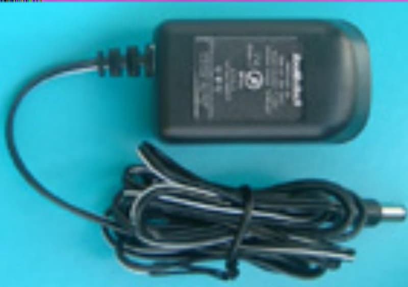
Click to zoom
Application Details
- Equipment Class
- DSC - Part 15 Security/Remote Control Transmitter
- Date of Grant
- Apr 18, 2002
- Application Purpose
- Original Equipment
- Date of Application
- Apr 18, 2002
- Equipment Note
- Wireless IR Remote Extender Transmitter
- Frequency Range
- 417.28100000 - 417.28100000
- Company
- RadioShack Corporation
- Country
- United States
Documents & Files
Document Text
Text extracted from the exhibit documents filed with the FCC. Open a document above to read the original.
Users Manual
Cat. No. 15-1950 OWNER'S MANUAL Please read before using this equipment. Wireless IR Remote Extender Thank you for buying the RadioShack Wireless IR Remote Extender. The extender increases your existing remote control’s operating range. The extended range lets you control your TV, VCR, stereo, CD player, or cable converter from greater distance than normally possible with existing remote controls without concern for line-of-sight requirements. Features include: Full remote Control Compatibility receives, converts, and relays infrared signals from virtually any infrared remote control. Powerful Radio Frequency lets you control audio/video equipment from up to 100 feet away, even from another room in your house. [warning and caution (risk of electric shock) wordings here] [lightning and exclamation wordings here] INSTALLATION Your RadioShack Wireless Infrared Remote Control Extender includes a transmitter and a receiver. The transmitter senses the infrared signals from your audio/video equipment’s remote controls and converts them into wireless transmissions. The receiver senses these transmissions, converts them back into identical infrared signals then relays them to your audio/video equipment. Installing the Receiver Follow these steps to install the receiver. 1. Place the receiver in front of the audio/video equipment and position it: o Within 20 feet of the audio/video equipment’s remote sensor o With the receiver’s front directly in front of the audio/video equipment’s remote sensor 2. Fully extend the telescopic antenna. Note: Rotate and adjust the receiver’s telescopic antenna for the best reception when you use it for the first time. 3. Connect the supplied AC adapter’s barrel plug into the DC 12V jack, then connect the adapter’s AC plug to a standard AC outlet. Cautions: o You must use a Class 2 power source that supplies 12V DC and delivers 120 mA. Its center tip must be set to positive and its plug must fit the receiver’s DC 12V jack. The supplied adapter meets these specifications. Using an adapter that does not meet these specifications could damage the receiver or the adapter. o Always connect the AC adapter to the receiver before you connect it to AC power. When you finish, disconnect the adapter from AC power before you disconnect it from the receiver. Connecting an IR Repeater You can connect the supplied IR repeater when you need to place the receiver next to your audio/video equipment instead of in front of it, or if your requirement is located inside a closed cabinet. You can connect the supplied IR repeater when you need to place the receiver next to your audio Follow these steps to connect the IR repeater. 1. Insert the repeater’s plug into the receiver’s 1/10-inch (2.4 mm) IR OUT jack. 2. Then position the repeater cord’s LED so the VCR’s remote sensor can pick up the signal it emits. Notes: o Do not place it directly in front of the remote sensor. o You can mount the IR repeater using its adhesive back to hold it steady. Installing the Transmitter Follow these steps to install the transmitter. 1. Place the transmitter away from the audio/video equipment and the extender’s receiver (in another room, for example) and position it: o Within 100 feet of the extender’s receiver o Within 20 feet of your remote control o With transmitter’s front facing your remote control 2. Connect the supplied AC adapter’s barrel plug into the transmitter’s DC 12V jack, then connect the adapter’s AC plug to a standard AC outlet. Caution: You must use a Class 2 power source that supplies 12V DC and delivers 120 mA. Its center tip must be set to positive and its plug must fit the transmitter’s DC 12V jack. The supplied adapter meets these specifications. Using an adapter that does not meet these specifications could damage the transmitter or the adapter. Note: The extender system’s LEDs (particularly the transmitter’s) might blink occasionally. This is caused by interference in the local vicinity and is normal. [THE FCC WANTS YOU TO KNOW wordings here] [CARE wordings here] SPECIFICATIONS Power Supply 120VAC/60Hz, 12VDC/120mA Transmitter Transmit Frequency 418 MHz Modulation Type ASK Transmit Power (EIRP) 1mW (FCC) Frequency Accuracy ±1 MHz Remote Range (R/C to TX) 20 Feet, Vertical ± 30°/Horizontal ± 15° . Extension Range (TX to RX) 100 Feet Min. Receiver Operation Frequency 418 ± 1 MHz Input Sensitivity −85dB Min. Remote Range (RX to VCR) 20 Feet, Vertical ±30°/Horizontal ±15° External IR Jack 2.4 mm Operating Temperature 32° to 104° F (0° to 40°C) Dimensions (HWD) 2 5/8 x 3 7/8 x 3 1/16 Inches (66 x 99 x 78 mm) Weight Receiver 3.17 oz (90 g) Transmitter 3.53 oz (100 g) Specifications are typical; individual units may vary. Specifications are subject to change and improvement without notice. 90 days warranty 05A02 RadioShack Corporation 15-1950 Fort Worth, Texas 76102 Printed in China
External Photos
ETC Report No.:ET91R-03-023-01 FCC ID.: AAO1501950 Rev. No 1.0 CONSTRUCTED PHOTOS of EUT Front View of EUT Rear View of EUT ETC Report No.:ET91R-03-023-01 FCC ID.: AAO1501950 Rev. No 1.0 CONSTRUCTED PHOTOS of EUT Top View of EUT Bottom View of EUT ETC Report No.:ET91R-03-023-01 FCC ID.: AAO1501950 Rev. No 1.0 CONSTRUCTED PHOTOS of EUT Front View of Adaptor Rear View of Adaptor
ID Label/Location Info
40mm
Internal Photos
ETC Report No.:ET91R-03-023-01 FCC ID.: AAO1501950 Rev. No 1.0 CONSTRUCTED PHOTOS of EUT Internal View of EUT Component View of Main PCB ETC Report No.:ET91R-03-023-01 FCC ID.: AAO1501950 Rev. No 1.0 CONSTRUCTED PHOTOS of EUT Solder View of Main PCB Front View of IR Box ETC Report No.:ET91R-03-023-01 FCC ID.: AAO1501950 Rev. No 1.0 CONSTRUCTED PHOTOS of EUT Rear View of IR Box Component View of IR PCB ETC Report No.:ET91R-03-023-01 FCC ID.: AAO1501950 Rev. No 1.0 CONSTRUCTED PHOTOS of EUT Solder View of IR PCB Solder View of Adaptor’s PCB ETC Report No.:ET91R-03-023-01 FCC ID.: AAO1501950 Rev. No 1.0 CONSTRUCTED PHOTOS of EUT Component View of Adaptor’s PCB Solder View of Adaptor’s PCB
Operational Description
15-1950 working principals ir; infrared ray; remote control is spread used at family house, unfortunately ir natural is working under line of sight , So ir remote control is no way to work properly room by room due to space shielding by wall . including carrier and coding, ir remote control signal detected by ir senser. then the senser transfer current to voltage and amplified by following booster circuit. The colpitts LC oscillator resonate at 418MHz, trigger to oscillate is controlled by boosted ir signal . in other words, via the ASK ;Amplitude Shift Keying; modulation, ir signal was carried on the 418MHz radio. using the basic regenerative receiver to recover the modulated IR signal,which drive ir-led to duplicate ir remote control signal.
Test Report
Rev. No 1.0 FCC Part 15 EMI TEST REPORT of E.U.T. : Wireless IR Remote Extender FCC ID. : AAO1501950 MODEL : 15-1950 Working Frequency : 417.281 MHz for APPLICANT : RadioShack Corporation ADDRESS : 100 Throckmorton St Ste 1300 Fort Worth, TX 76102-2802 Test Performed by ELECTRONICS TESTING CENTER, TAIWAN NO. 34, LIN 5, DING FU TSUN, LINKOU HSIANG TAIPEI HSIEN, TAIWAN, R.O.C. Tel:(02)26023052, 26023054 Fax:(02)26010910 Report Number : ET91R-03-023-01 ETC Report No.:ET91R-03-023-01 FCC ID.: AAO1501950 Rev. No 1.0 TEST REPORT CERTIFICATION Applicant : RadioShack Corporation 100 Throckmorton St Ste 1300 Fort Worth, TX 76102-2802 Manufacturer : TRANS ELECTRIC CO., LTD. 765, Sec. 2, Changsan Road, Huatan, Changhua, Taiwan, R.O.C. Description of EUT : a) Type of EUT : Wireless IR Remote Extender b) Trade Name : RadioShack c) Model No. : 15-1950 d) FCC ID : AAO1501950 e) Working Frequency : 417.281 MHz f) Power Supply : Adaptor; I/P: AC 120V, 60Hz; O/P: DC 12V, 120mA Regulation Applied : FCC Rules and Regulations Part 15 Subpart C (2001) I HEREBY CERTIFY THAT; The data shown in this report were made in accordance with the procedures given in ANSI C63.4 and the energy emitted by the device was founded to be within the limits applicable. I assume full responsibility for accuracy and completeness of these data. Note : 1. The results of the testing report relate only to the items tested. 2. The testing report shall not be reproduced except in full, without the written approval of ETC. Issued Date : Apr. 16, 2002 Test Engineer : ( S. S. Liou ) Approve & Authorized Signer : Will Yauo, Manager EMC Dept. II of ELECTRONICS TESTING CENTER, TAIWAN ETC Report No.:ET91R-03-023-01 FCC ID.: AAO1501950 Rev. No 1.0 Table of Contents Page 1. GENERAL INFORMATION .................................................................................................................................. 1 1.1 PRODUCT DESCRIPTIO N............................................................................................................................................ 1 1.2 CHARACTERISTICS OF DEVICE:.................................................................................................................................. 1 1.3 TEST METHODOLOGY................................................................................................................................................ 1 1.4 TEST FACILITY.......................................................................................................................................................... 1 2. DEFINITION AND LIMITS.................................................................................................................................... 2 2.1 DEFINITION............................................................................................................................................................... 2 2.2 RESTRICTED BANDS OF OPERATION.......................................................................................................................... 2 2.3 LIMITATION............................................................................................................................................................... 2 2.4 LABELIN G REQ UIREMEN T.......................................................................................................................................... 4 2.5 USER INFORMATION.................................................................................................................................................. 4 3 SYSTEM TEST CONFIGURATION...................................................................................................................... 5 3.1 JUSTIFICATIO N.......................................................................................................................................................... 5 3.2 DEVICES FO R TESTED SYSTEM................................................................................................................................... 5 4. RADIATED EMISSION MEASUREMENT.......................................................................................................... 6 4.1 APPLICABLE STANDARD............................................................................................................................................ 6 4.2 MEASUREMEN T PROCEDURE...................................................................................................................................... 6 4.3 TEST DATA................................................................................................................................................................ 8 4.4 FIELD STREN GTH CALCULATIO N................................................................................................................................9 4.5 ACTIVATE TIME......................................................................................................................................................... 9 4.6 CALCULATION OF DUTY FACTOR.............................................................................................................................. 9 4.7 RADIATED TEST EQUIPMENT................................................................................................................................... 10 4.8 MEASURIN G IN STRUMEN T SETUP............................................................................................................................. 10 4.9 RADIATED MEASUREMEN T PHOTOS......................................................................................................................... 11 5. BANDWIDTH OF EMISSION.............................................................................................................................. 12 5.1 APPLICABLE STANDARD PLO T GRAPHIC OF BANDWIDTH......................................................................................... 12 5.2 BANDWIDTH TEST …
Text truncated - open the document above for the full version.
Test Setup Photos
ETC Report No.:ET91R-03-023-01 FCC ID.: AAO1501950 Rev. No 1.0 Radiated Measurement Photos ETC Report No.:ET91R-03-023-01 FCC ID.: AAO1501950 Rev. No 1.0 Photos of Conduction Measuring Setup
Contact Information
Applicant
Elizabeth Granados(Regulatory Affairs Manager)
Test Firm
Electronics Testing Center, TaiwanWin-Po Tsai
Technical Specifications
| # | Rule Parts | Frequency Range | Power Output |
|---|---|---|---|
| 1 | 15.231 | 417.281 MHz - 417.281 MHz | - |
Other Applications from RadioShack Corporation

AAO2302500
Feb 10, 2015Bluetooth Power Bank
Equipment Class
DXX - Part 15 Low Power Communication Device Transmitter
AAO4300124C
May 02, 2013900MHz Wireless Intercom
Equipment Class
DXT - Part 15 Low Power Transceiver, Rx Verified
AAO1200876
Nov 30, 2011Universal FM Transmitter
Equipment Class
DXX - Part 15 Low Power Communication Device Transmitter
AAO1200962
Aug 02, 2011Universal FM Transmitter
Equipment Class
DXX - Part 15 Low Power Communication Device Transmitter
AAO1500044T
Apr 02, 20112.4GHz Digital Wireless Rear Speaker Kit - Transmitter
Equipment Class
DSS - Part 15 Spread Spectrum Transmitter