AAO1501971-TVideo Sender
RadioShack Corporation
Click to zoom
Application Details
- Equipment Class
- CRR - Superregenerative Receiver
- Date of Grant
- Mar 15, 1999
- Application Purpose
- Original Equipment
- Date of Application
- Jan 13, 1999
- Equipment Note
- Video Sender
- Frequency Range
- 310.00000000 - 310.00000000
- Company
- RadioShack Corporation
- Country
- United States
Documents & Files
Document Text
Text extracted from the exhibit documents filed with the FCC. Open a document above to read the original.
Users Manual
OWNER'S MANUAL Video Sender AUDIO/VIDEO EXTENDER SYSTEM MODEL 15-1971 (INCLUDES 15-1971T, TRANSMITTER AND 15-1971R, RECEIVER, PLUS TWO PLUG -IN POWER SUPPLIES, AND ALL REQUIRED CONNECTING CABLES) 2 VK30A -6/98 INTRODUCTION Your Wireless Video Sender kit consists of a transmitter base unit which connects to your DSS receiver, and a receiver unit which connects to the TV in another room. The Video Sender Transmitter converts the A/V signal from your DSS into a radio signal and transmits it (even through walls) to the Video Sender Receiver unit. The Video Sender Receiver converts the signals back to A/V signals which are fed through a cable to your TV's A/V input jacks. When used with plug 'n power universal remotes your Video Sender also allows you to operate your DSS while watching it in another room. By purchasing an optional Remote Control Extender (Cat. No. 15-1959) can control other A/V products such as VCRs, Cable Boxes, etc. while watching a TV in another room. There are just a few simple steps to follow to hook up your Video Sender kit to a DSS, VCR or Cable Box. WARNING: To reduce the risk of fire or electric shock, do not expose this product to rain or moisture. 3 VK30A - 6/98 IMPORTANT SAFETY INSTRUCTIONS 1.Read Instructions - All the safety and operating instructions should be read before the product is operated. 2.Retain Instructions - The safety and operating instructions should be retained for future reference. 3.Heed Warnings - All warnings on the product and in the operating instructions should be adhered to. 4.Follow Instructions - All operating and use instructions should be followed. 5.Cleaning - Unplug this product from the wall outlet before cleaning. Do not use liquid cleaners or aerosol cleaners. Use a damp cloth for cleaning. 6.Attachments - Do not use attachments not recommended by the product manufacturer as they may cause hazards. 7.Water and Moisture - Do not use this product near water - for Example, near a bath tub, wash bowl, kitchen sink, or laundry tub, in a wet basement, or near a swimming pool; and the like. 8.Accessories - Do not place this product on an unstable cart, stand, tripod, bracket, or table. The product may fall, causing serious injury to a child or adult, and serious damage to the product. Use only with a cart, stand, tripod, bracket, or table recommended by the manufacturer, or sold with the product. Any mounting of the product should follow the manufacturer’s instructions, and should use a mounting accessory recommended by the manufacturer. 9.A product and cart combination should be moved with care. Quick stops, excessive force and uneven surfaces may cause the product and cart combination to overturn. 10. Ventilation - Slots and openings in the cabinet are provided for ventilation and to ensure reliable operation of the product and to protect if from overheating, and these openings must not be blocked or covered. The openings should never be blocked by placing the product on a bed, sofa, rug, or other similar surface. This product should not be placed in a built-in installation such as a bookcase or rack unless proper ventilation is provided or the manufacturer’s instructions have been adhered to. 11. Power Sources - This product should be operated only from the type of power 4 VK30A -6/98 source indicated on the marking label. If you are not sure of the type or power supply to your home, consult your product dealer or local power company. For products intended to operate from battery power, or other sources, refer to the operating instructions. 12. Grounding or Polarization - This product is equipped with a polarized alternating current line plug (a plug having one blade wider than the other). This plug will fit into the power outlet only one way. This is a safety feature. If you are unable to insert the plug fully into the cutlet, try reversing the plug. If the plug should still fail to fit, contact your electrician to replace your obsolete outlet. Do not defeat the safety purpose of the polarized plug. 13. Power-Cord Protection - Power supply cords should be routed so that they are not likely to be walked on or pinched by items placed upon or against them, paying particular attention to cords at plugs, convenience receptacles, and the point where they exit from the product. 14. Lightning - For added protection for this product during a lightning storm, or when it is left unattended and unused for long periods of time, unplug it from the wall outlet and disconnect the antenna or cable system. This will prevent damage to the product due to lightning and power-line surges. 15. Overloading - Do not overload wall outlets, extension cords, or integral convenience receptacles as this can result in a risk of fire or electric shock. 16. Object and Liquid Entry - Never push objects of any kind into this product through openings as they may touch dangerous voltage points or short-out parts that could result in a fire or electric shock. Never spill liquid of any kind on the product. 17. Servicing - Do not attempt to service this product yourself as opening or removing covers may expose you to dangerous voltage or other hazards. Refer all servicing to qualified service personnel. 18. Damage Requiring Service - Unplug this product from the wall outlet and refer servicing to qualified service personnel under the following conditions: a)When the power-supply cord or plug is damaged, b)If liquid has been spilled, or objects have fallen into the product, c)If the product has been exposed to rain or water, 5 VK30A - 6/98 d)If the product does not operate normally by following the operating instructions. Adjust only those controls that are covered by the operating instructions as an improper adjustment of other controls may result in damage and will often require extensive work by a qualified technician to restore the product to its normal operation, e)If the product has been dropped or damaged in any way, and f)When the product exhibits a distinct change…
Text truncated - open the document above for the full version.
Block Diagram
Left Audio Input Right Audio Input Video Input FM ModulatorFM ModulatorPre-emphasis 310MHz Receiver IR Driver DSS control output 310MHz 2.4GHz RFTransmitter 2.4GHz Patch Antenna 4-Channels Selector Block Diagram for Video Sender Transmitter (VT30A)
ID Label/Location Info
Cat. No. 15-1971 rating label Cat. No. 15-1971 (Sender) This device complies with part 15 of the FCC rules. Operation is subject to the following two conditions: (1) This device may not cause harmful interfer- ence, and (2) This device must accept any interference received, including interference received, including interference that may cause undesired operation. 2.4 GHz WIRELESS AUDIO/VIDEO DISTRIBUTION SYSTEM For use with Cat. No. 15-1971 (Receiver) and Adaptor for 15-1971 Sender Ratings: 12VDC, 200 mA max. For indoor use only. Refer to Owner's Manual for more information. FCC ID: AAO1501971-T Custom Manufactured in China for RadioShack. A Division of Tandy Corporation, Ft. Worth, TX 76102 ®
Operational Description
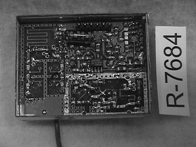
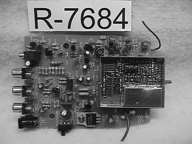
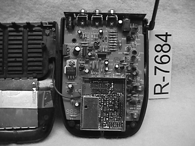
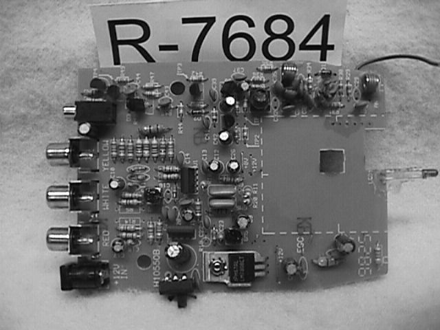
310 Mhz Superregenerative Receiver Operational Description The 310 MHz receiver receives a pulsed 310 MHz RF signal from a universal RCA remote control such as the model RCSAT (FCC ID: B4SRCSAT2). The signal is then converted to an Infrared format and sent to the IR extender jack on the Audio/Video Sender. A cable can then be attached to a RCA DSS receiver at the IR control Input. This signal is used to remotely change channels on some RCA DSS receivers.
Test Report
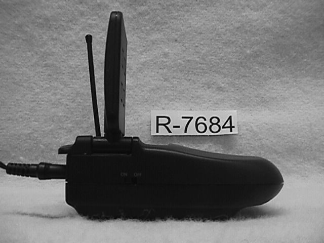
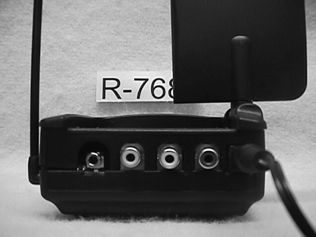
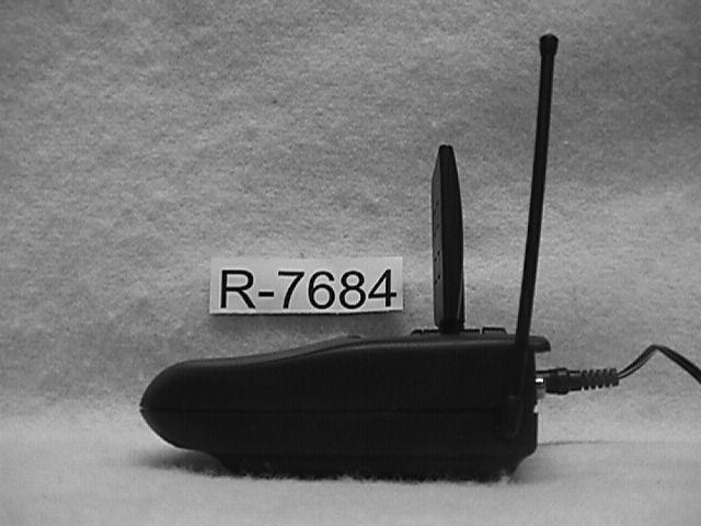
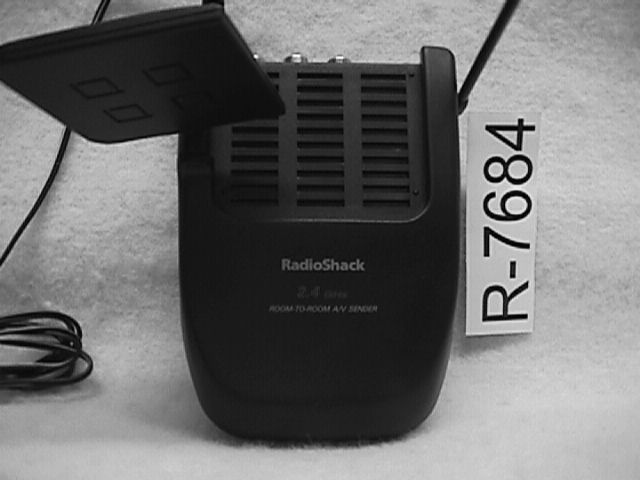
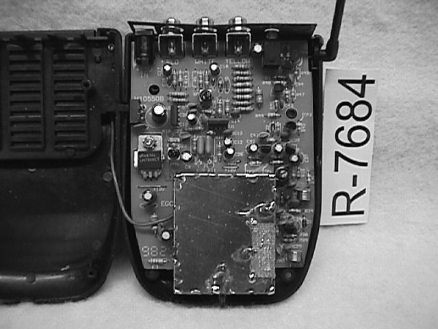
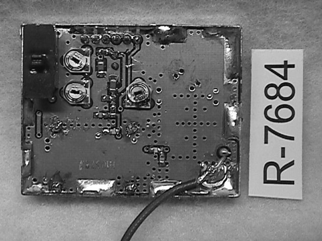
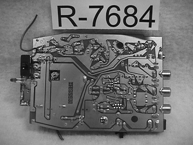
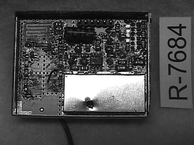
REPORT No. R-7684-3 FCC COMPLIANCE TEST REPORT ON RadioShack 310MHz Superregenerative Receiver Model: 15-1971T FCC ID: AAO1501971-T Customer Name:RadioShack Customer P.O.:Verbal Test Method:ANSI C63.4:1992 Test Specification:FCC Rules & Regulations Part 15 Date of Report:January 11, 1999 RETLIF Test Report No.:R-7684-3 Test Engineer:T.J. Schneider Report Written By:R. Stremel Supervisor:R.J. Reitz Our letters and reports are for the exclusive use of the customer to whom they are addressed, and their communication to any other or the use of the name of RETLIF TESTING LABORATORIES must receive our prior written approval. Our letters and reports apply only to the sample tested and are not necessarily indicative of the qualities of apparently identical or similar products. The reports and letters and the name of RETLIF TESTING LABORATORIES or insignia are not to be used under any circumstances in advertising to the general public. REPORT No. R-7684-3 TABLE OF EXHIBITS Exhibit 1Installation and Operating Instructions per 2.1033(b)(3) Exhibit 2Technical Description per 2.1033(b)(4) Exhibit 3Block Diagram and Schematics per 2.1033(b)(5) Exhibit 4Report of Measurements - Receiver Portion - per 2.1033(b)(6) Exhibit 5Equipment Photographs and Label per 2.1033(b)(7) REPORT No. R-7684-3 EXHIBIT 1 Installation and Operating Instructions Para. 2.1033(b)(3) REPORT No. R-7684-3 EXHIBIT 2 Technical Description Para. 2.1033(b)(4) REPORT No. R-7684-3 Technical Report 2.1033(b)(4) Equipment Manufacturer X-10 Electronics Shenzhen Co. Ltd. X-10 Building Labour Industrial District Shenzhen, Xixiang, Bao An Guang Dong, China, 518102 FCC Identifier AAO1501971-T Operating Instructions See Exhibit 1 Trade Name X-10 PowerHouse Model Number 15-1971T Additional Model Numbers and Trade Names Not Applicable REPORT No. R-7684-3 EXHIBIT 3 Block Diagram and Schematic Para. 2.1033(b)(5) REPORT No. R-7684-3 EXHIBIT 4 Report of Measurements Para. 2.1033(b)(6) REPORT No. R-7684-3 X-10 USA, Inc. 91 Ruckman Road Closter, NJ 07624 MANUFACTURER X-10 Electronics Shenzhen Co. Ltd. X-10 Building Labour Industrial District Shenzhen, Xixiang, Bao An Guang Dong, China, 518102 TEST SPECIFICATION:Part 15, Subpart B Certification TEST PROCEDURE: ANSI C63.4:1992 TEST SAMPLE DESCRIPTION BRANDNAME:X-10 PowerHouseMODEL:VT30A TYPE:310MHz Superregenerative Receiver POWER REQUIREMENTS:12 VDC FREQUENCY RANGE:310MHz TESTS PERFORMED Para. 15.107(a), Conducted Emissions, Receiver Locked Para. 15.109(a), Radiated Emissions, Receiver Locked I HEREBY CERTIFY THAT: The measurements shown here were in accordance with the procedure indicated and that the energy emitted by this equipment was found to be within the limits applicable. I assume full responsibility for the accuracy and completeness of these measurements and vouch for the qualifications of all persons taking them. I FURTHER CERTIFY THAT: On the basis of the measurements made, the device tested is capable of operation in compliance with the requirements of Part 15 of the FCC Rules under normal use and maintenance. SIGNPRINT Thomas J. Schneider TITLE EMC Test Engineer REPORT No. R-7684-3 Test Procedures Used The test procedures used for all testing follow the guidelines specified in the applicable FCC specification and general industry practices. Although test procedures may sometimes have to be modified to address the needs of specific test samples, the following forms the basis for all testing programs: Conducted Emissions - All testing was performed with the test sample placed 80cm above a 2.5 x 3M ground plane and 1 meter from any other grounded surface. The power cord of the test sample was connected to the Line Impedance Stabilization Networks, which in turn, had their cases mounted to the ground plane. With the equipment connected as stated, an EMI meter or spectrum analyzer was connected to the LISN and the conducted emissions were measured over the frequency range of 450KHz to 30MHz, in turn on each of the input power leads. Care was taken during testing to relocate all system components and cabling in an effort to maximize the emissions from the EUT. Radiated Emissions - Radiated emissions testing was performed on an FCC listed 3 meter open field test site over the frequency range of 30MHz to 2000MHz. Prior to open field testing, pre-scan testing was performed inside of a shielded enclosure in order to obtain a spectrum signature of the unit and to use the data obtained as a guideline for open field testing. When the test sample is taken to the open field tests site, it is placed on a one meter high wooden turntable. A spectrum analyzer or EMI meter is then connected to either the biconical or log periodic anenna, depending on frequency range being scanned. The antenna is mounted on a remote controlled four meter antenna mast. The frequency range was then scanned and each measurement taken was maximized by performing the following: (1) Raising and lowering the measurement antenna. (2) Rotating the measurement antenna to both the horizontal and vertical polarizations. (3) Tuning the measurement antenna to the frequency of measurement. (4) Rotating the test sample, and (5) Relocating all interconnecting and input power cables. In the event that testing was extended above or below the frequency range of 30MHz to 1000MHz, loop antennas were used for all measurements below 30MHz and horn antennas were used for all measurements above 1000MHz. REPORT No. R-7684-3 REPORT OF MEASUREMENTS RADIATED EMISSIONS PARA. 15.109(a) REPORT No. R-7684-3 TEST PERFORMEDMODEL NUMBER Radiated EmissionsX-10 PowerHouse FCC Part 15/B/BVT30A E.U.T. CONFIGURATION JUSTIFICATION The test sample, with cables connected, was arranged on the test stand. This configuration was rotated and all power cables were relocated in order to maximize the emissions from the E.U.T. The test antenna was raised, lowered and both vertically and horizontally polarized to further maximize the emissions (polarization is dependent on the fre…
Text truncated - open the document above for the full version.
Test Report
Retlif Testing Laboratories R Retlif Job Number R-7684-3 Data Sheet 1 of 1 Test Method: FCC Part 15 Radiated Emissions, 30 MHz to 2 GHz Customer: Radio Shack Job No. R-7684-3 Test Sample: Superregenerative Receiver FCC ID: AAO1501971-T Model No.: Cat. # 15-1971T Serial No. N/A Operating Mode: Continuously receiving 310 MHz Signal Technician: Dennis Cortes Date: December 21, 1998 Notes: Detector Function: Quasi-Peak (Peak above 1 GHz)Temp: 11CHumidity: 81% Test Distance: 3 meters Test Freq. Antenna Position Turntable Position Meter Reading Correction Factor Corrected Reading Converted Reading QP Limit MHz(H/V) –HeightDegreesdBuVdBdBuV/muV/muV/m 30.0100 || VV 88.00100 88.00150 || VV 216.00150 216.00200 || V| 305.50V-1.522540.3-4.136.264.6| 307.00V-1.522540.7-4.036.768.4| 308.50V-1.522542.1-4.038.180.4| 311.50V-1.522544.0-3.840.2102.3| 313.10V-1.522543.6-3.839.897.7| 314.60V-1.522542.4-3.738.786.1| 316.10V-1.522540.8-3.637.272.4| 317.60V-1.522538.3-3.634.754.3| 932.90V-1.022530.47.537.978.5| 934.50V-1.022530.67.638.281.3| 935.90V-1.022530.97.738.685.1| 938.90V-1.022531.07.838.887.1| || VV 960.00200 960.00500 || V| 1204.80V-1.222549.9-6.443.8154.9| 1269.00V-1.522550.8-3.647.2229.1| || || VV 2000.00500 The frequency range was scanned form 30 MHz to 24 GHz. All emissions not recorded were more then 20dB below the specified limit. Emission observed from the EUT do not exceed the specified limit.
Contact Information
Applicant
Elizabeth Granados(Regulatory Affairs Manager)
Technical Contact
Retlif Testing LaboratoriesThomas J Schneider
[email protected]516-737-1500
795 Marconi Avenue · Ronkonkoma, New York · United States
Test Firm
Retlif Testing LaboratoriesMichael Bozza
Technical Specifications
| # | Rule Parts | Frequency Range | Power Output |
|---|---|---|---|
| 1 | 15B | 310 MHz - 310 MHz | - |
Other Applications from RadioShack Corporation

AAO2302500
Feb 10, 2015Bluetooth Power Bank
Equipment Class
DXX - Part 15 Low Power Communication Device Transmitter
AAO4300124C
May 02, 2013900MHz Wireless Intercom
Equipment Class
DXT - Part 15 Low Power Transceiver, Rx Verified
AAO1200876
Nov 30, 2011Universal FM Transmitter
Equipment Class
DXX - Part 15 Low Power Communication Device Transmitter
AAO1200962
Aug 02, 2011Universal FM Transmitter
Equipment Class
DXX - Part 15 Low Power Communication Device Transmitter
AAO1500044T
Apr 02, 20112.4GHz Digital Wireless Rear Speaker Kit - Transmitter
Equipment Class
DSS - Part 15 Spread Spectrum Transmitter