AAO1901104
RadioShack Corporation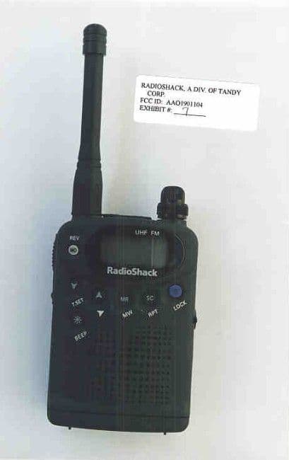
Click to zoom
Application Details
- Equipment Class
- CSR - Scanning Receiver
- Date of Grant
- May 20, 1999
- Application Purpose
- Original Equipment
- Date of Application
- Apr 12, 1999
- Frequency Range
- 420.00000000 - 470.00000000
- Company
- RadioShack Corporation
- Country
- United States
Documents & Files
Document Text
Text extracted from the exhibit documents filed with the FCC. Open a document above to read the original.
Users Manual
Cat. No. 19-1104 OWNER’S MANUAL Pleas e read before using this equipment. HTX-400 Mini Handheld 70cm FM Amateur Transceiver 19-1102.fm Page 1 Friday, March 19, 1999 4:08 PM 2 FEATURES Your RadioShack HTX-400 Mini Handhel d 70cm FM Ama- teur Transceiver is compact and lightweight, making it easy to carry almost anywhere. The crystal controlle d cir cuitry pro vides acc urate and stable channel selecti on, making i t an ideal choice for your amate ur communications needs. Note : You must have a Technician Class or higher Amate ur Ra- dio Operator’s License, and a call s ign issued by the FCC, to le- gally transmit using thi s transceiver. Transmitting without a lic ense carries heavy penalties. Getting a license is easier than ever. See “Introduction to Amateur Radio” on Page 7 for more in- formati on. Here are some of your transceiver’s features. 200 mW/2 Watt Output — the transceiver automat ically trans- mits at 200 mW out put when powered by internal batteries, or at 2 Watt output when powered by an ext ernal 9-volt p ower source. CTCSS (Continuous Tone Coded Squelch Syste m subaudi ble tone) — hel ps reduc e interference from other nearby sys tems op- erating on the same frequency. Encoding and decoding tone un- loc ks squelch when received. Repeater Offset — lets you select a n appropriate offset v alue to match a local repeater. Scan — the transc ei ver scans frequency range and memory channels for transmissions. Power Save — conserves battery power when the transceiver is not transmitting or receiving. Programmable Frequency Steps — let you set the frequency increment for tunin g or scanning to 5, 10, 12.5, 15, 20, 25, 50 kHz, or 1 MHz steps. ©1999 Tandy Corporation. All Rights Reserved. RadioShack is a re gistere d trademark used by Tandy Corpora tion. 19-1102.fm Page 2 Friday, March 19, 1999 4:08 PM 3 Alert Melody — you can set the radio to play a short, selectable melody when it transmits, and play the same melody when it re- ceives a tone encoded signal. Signal Strength Indicator — a graduated bar shows the relative strength of the received signal. Time-Out Timer — lets you set a maximum transmission time in- terval from 0 to 990 seconds to make the best use of repeater transmission time. Busy Channel Lock Out — prevents transmitting while the se- lected channel is receiving a signal. TX Delay — continues transmitting to prevent noise at the end of a transmission as you release the push-to-talk (PTT) button. Scan Delay — delays restart of scanning when the radio locks onto a channel. Earphone Jack and External Microphone Jack — let you con- nect an optional earphone, external microphone, or combination headset for more flexible operation. External Power Jack — lets you use an external power source for maximum output. 30 Memory Locations — let you store up to 30 frequencies and other settings. Back Light — makes your transceiver easy to operate in low- light situations. Key Lock — lets you lock the transceiver’s keys to prevent acci- dentally changing settings. We recommend you record your transceiver’s serial number here. The number is on the transceiver’s back panel. Serial Number ____________________________ 19-1102.fm Page 3 Friday, March 19, 1999 4:08 PM 4 MANUAL CONVENTIONS Your transceiver’s buttons perform multipl e functio ns. The abbre- via tion or symbol for a functio n is print ed on, bel ow, or above each button. To activate cert ain tra nsceiver features, you must pre ss FUNC (functi on) and another button at t he same time. Those key com- bination instructions are printed as first button name, +, then the second button name. For example, FUNC + LOCK means hold down FUNC while you pre ss LOCK . Button names are printed in small, bold, capit al letters such as BEEP or SC . Wor ds, symbols, and numbers that appear on the display are printed using a disti nctive typ eface suc h as 446.000 or BUSY . FCC INFORMATION This device complie s with Part 15 of the FCC Rules. Operation is subject to the following two condi tions: (1) This device may not cause harmful interference, and (2) this device must accept any interference received, including interference that may cause un- desired operation. 19-1102.fm Page 4 Friday, March 19, 1999 4:08 PM 5 CONTENTS Introduction to Amateur Radio .................................. 7 Preparation .................................................................. 9 Power Sources ....................................................... 9 Using Internal Batteries .................................. 9 Testing Internal Batteries .............................. 10 Using Vehicle Battery Power ......................... 11 Connecting the Antenna ...................................... 12 Attaching the Belt Clip ......................................... 13 Attaching the Wrist Strap ..................................... 13 Connecting a Microphone/Speaker ...................... 14 A Quick Look at the Controls .................................. 15 Operation ................................................................... 17 Understanding Repeaters .................................... 17 Receiving, Transmitting and Setting Squelch ....... 17 Scanning for Active Frequencies ......................... 19 Monitoring a Frequency ....................................... 19 Changing the Frequency Range .......................... 19 Locking the Keypad .............................................. 20 Lighting the Display .............................................. 20 Turning the Key tone On and Off ......................... 20 Using Memory Locations ..................................... 20 Using the Calling-Frequency Memory Location .......................................... 20 Using Standard Memories ................................... 21 Storing a Transmit/Receive Frequency ......... 21 Storing a Repeater Offset Frequency ........... 22 Storing a Scanning Skip Setting ................... 22 Scanning Standard Memory Locations ......... 23 Locking Out (Skippin…
Text truncated - open the document above for the full version.
Block Diagram
Service HTX-400 MINI HANDHELD 70cm FM AMATEUR TRANSCEIVER Catalog Number : 19-1104 CONTENTS page Specifications ----------------------------------------------------------------------------------------------- 1 Theory of Operation --------------------------------------------------------------------------------------- 2 Block Diagram ---------------------------------------------------------------------------------------------- 8 Alignment Instructions ------------------------------------------------------------------------------------ 9 Test Equipment Set-Up --------------------------------------------------------------------------------- 12 Semiconductor Lead Identification and IC Internal Diagram ---------------------------------- 15 PCB Views ------------------------------------------------------------------------------------------------- 25 Wiring Diagram ------------------------------------------------------------------------------------------- 29 Troubleshooting Chart ---------------------------------------------------------------------------------- 30 Exploded View of Unit ---------------------------------------------------------------------------------- 31 Whole Parts List ------------------------------------------------------------------------------------------ 32 Schematic Diagrams ------------------------------------------------------------------------------------ 40 ®œ 1999 Tandy Corporation All Rights Reserved. RadioShack is a registered trademark used by Tandy Corporation 1 SPECIFICATIONS 1. GENERAL FREQUENCY : RX -------------------------------------------------------- 420-470 MHz TX --------------------------------------------------------- 430-470 MHz FREQUENCY GENERATION ------------------------ PLL SYNTHESIZER FREQUENCY STABILITY ---------------------------- °æ5 PPM OPERATING TEMPERATURE ---------------------- 14¢™ TO 131¢™F (-10°... TO 55°...) POWER SOURCE -------------------------------------- DC 3.0V TO 9V MODULATION -------------------------------------------- F3E IMPEDANCE ---------------------------------------------- 50 ohm DIMENSIONS (HWD) ----------------------------------- 2 1 / 4 °ø3 3 / 8 °ø1 1 / 16 inches 85°ø58°ø26.5 mm WEIGHT (without batteries) --------------------------- 4.2 oz (120g) 2. RECEIVER SECTION CIRCUIT TYPE ------------------------------------------- DUAL CONVERSION, SUPERHETERODYNE IF FREQUENCY : 1st IF ----------------------------------------------------- 30.85 MHz 2nd IF ---------------------------------------------------- 450 KHz SENSITIVITY ---------------------------------------------- 0.22•ÏV for 12dB SINAD SELECTIVITY --------------------------------------------- 50 dB Min. SPURIOUS & IMAGE REJECTION ----------------- 40 dB Min. INTERMODULATION ----------------------------------- 50 dB Min. DISTORTION --------------------------------------------- 10 % Max. S/N RATIO ------------------------------------------------- 40 dB Min. AUDIO OUTPUT @10%THD ------------------------- 80 mW 16 Ohm, BTL 3. TRANSMITTER SECTION POWER OUTPUT --------------------------------------- 300 mW DISTORTION ---------------------------------------------- 10 % DEVIATION ----------------------------------------------- °æ 5.2 KHz S/N RATIO ------------------------------------------------- 35 dB CURRENT DRAIN ---------------------------------------- 600 mA 2 THEORY OF OPERATION 1. SEMICONDUCTORS AND FUNCTION 1.1 IC COMPLEMENT REF.NO TYPE MANUFACTURER FUNCTION IC601 IC801 IC802 IC806 IC501 IC3 IC805 IC401 IC803 IC807 IC804 IC808 TK11230AM TMP87PP21DF 24LC16B NJM2902V LV2105V NJM2073M FX465DF TA31136FN TK11230AM NJM2904V XC6371A350PR AS2801M TOKO THOSHIBA PRO-CHIPS JRC SANYO JRC MX-COM TOSHIBA TOKO JRC TORREX ALPHA IC-REGULATOR CPU IC EEPROM MIC AMP PLL IC AUDIO POWER AMP CTCSS ENCODER IC-IF IC-REGULATOR TONE AMP D/D CONVERTOR IC-REGULATOR 1.2 TRANSISTOR COMPLEMENT REF.NO TYPE MANUFACTURER FUNCTION Q101 Q102 Q103 Q104 Q105 Q106 Q201 Q202 Q203 Q305 Q304 Q302 Q303 Q301 Q501 Q601 Q602 Q603 Q604 Q606 Q607 Q801 Q805 Q804 Q810 Q107 MRF9242T1 MMBR951LT1 MMBR951LT1 2SC3356 2SC3356 KTA1001S 2SC4226 2SC4226 KTC4081 KRC104S 2SC3356 MMBR951 MMBR951 KTC3875 KRC410 KRA310 KRA310 KRA310 KRA310 KRC404 KTA2015 KTC3875 KRC104 KRA110 2SJ144 KRC401 MOTOROLA MOTOROLA MOTOROLA NEC NEC KEC NEC NEC KEC KEC NEC MOTOROLA MOTOROLA KEC KEC KEC KEC NEC KEC KEC KEC KEC KEC KEC NEC KEC FINNAL RF AMP DRIVER AMP PREDRIVER AMP BUFFER BUFFER TX S/W 1'ST AMP 1'ST MIXER IF AMP VCO R/TX S/W VCO OSC VCO BUFFER VCO BUFFER VCO REG PLL LOCK S/W RX B+ S/W SAVE B+ S/W TX EN1 B+ S/W TX EN2 B+ S/W AUDIO MUTE S/W AUDIO B+ S/W LAMP S/W RESET S/W PTT S/W RX MUTE S/W TX S/W 3 1.3 DIODE COMPLEMENT REF.NO TYPE MANUFACTURER FUNCTION D804-805 D807 D806 D804A D830 D802 ZD803 LED801-802 D201-202 D101 D102 D303 D302 D601 D401 D301 1N4001(M2) 1N4001(M2) RB471E KDS187 MA77 KDS187 ZD7.5Y LED MA77 MA77 MA862 KDS114 KV1832 KDS181 MMBD101 1SV229 ROHM ROHM ROHM KEC PANASONIC KEC KEC EVERLIGHT PANASONIC PANASONIC PANASONIC KEC TOKO KEC MOTOROLA NEC REVERSE B+ PROTECT REG REVERSE PROTECT D/D CON S/W CTCSS COMPARATOR CLOCK SHIFT S/W MODEL SELECTOR PTT S/W BACKLIGHT LED RX LPF S/W TX LPF S/W R/TX LOCAL S/W R/TX VCO S/W VCO OSC RX B+ S/W SQ DET DEV. VARICAP °ÿ REMARKS. KEC : KOREA ELECTRONICS CO., LTD. ROHM : ROHM KOREA CORP. TOSHIBA : TOSHIBA CO. LTD MOTOROLA : MOTOROLA CO. LTD JRC : NEW JAPAN RADIO CO. LTD SANYO : SANYO ELECTRIC CO., LTD. TOKO : JAPAN TOKO CO., LTD PRO-CHIPS : JAPAN MICROCHIP CO., LTD TORREX : JAPAN TORREX CO., LTD EVERLIGHT : TAIWAN EVERLIGHT CO., LTD PHILLIPS : TAIWAN PHILLIPS CO., LTD ALPHA : ALPHA SEMICONDUCTOR CO., LTD MX-COM : MX°§ COM, INC. PANASONIC : MATSUSHITA ELECTRIC INDUSTRIAL CO., LTD 4 2. DESCRIPTION OF FREQUENCY DETERMINING AND STABILIZING CIRCUIT 2.1 INTRODUCTION THE FREQUENCIES FOR TRANSMITTER AND RECEIVER LOCAL FREQUENCIES ARE ALL DRIVED FROM A SINGLE 15.2 [MHz] VCTCXO BY MEANS OF A PHASE LOCKED LOOP. THE FIRST LOCAL OSCILLATOR FREQUENCIES ARE 389.15 [MHz] TO 439.15 [MHz]. THE SECOND LOCAL FREQUENCY …
Text truncated - open the document above for the full version.
Test Report
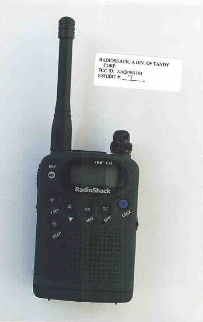
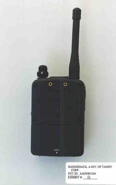
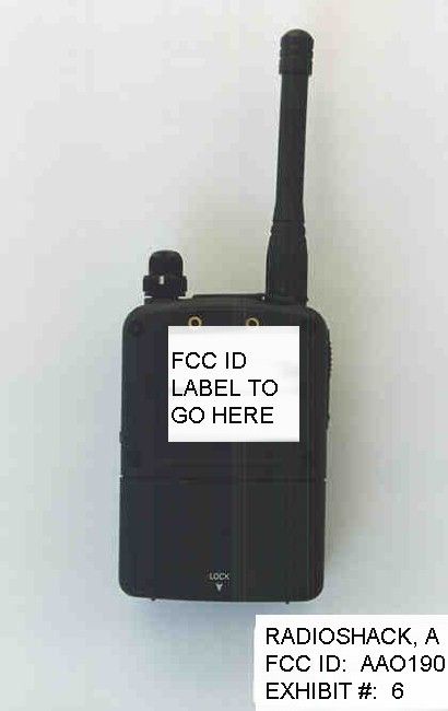
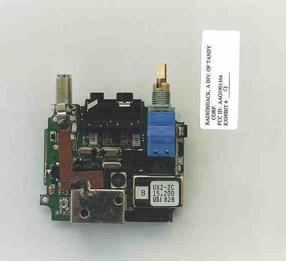
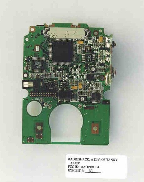
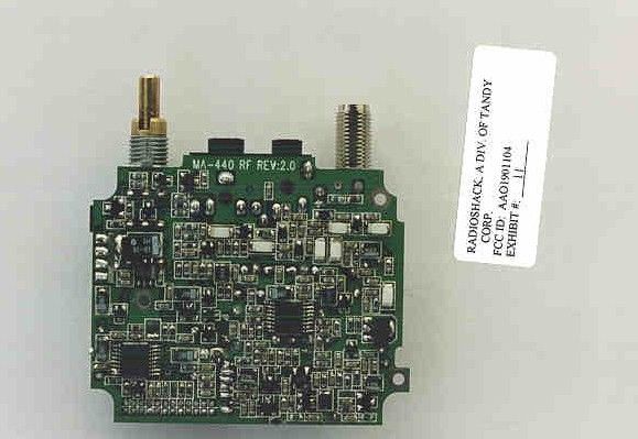
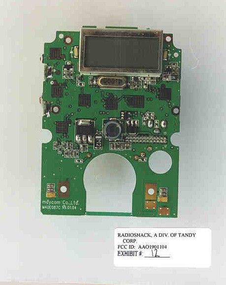
TABLE OF CONTENTS LIST APPLICANT: RADIOSHACK, A DIV. OF TANDY CORP. FCC ID: AAO1901104 TEST REPORT CONTAINING: PAGE 1......TEST PROCEDURE PAGE 2......TEST PROCEDURE & CIRCUIT DESCRIPTION PAGE 3......RADIATION INTERFERENCE TEST DATA EXHIBITS CONTAINING: EXHIBIT 1............POWER OF ATTORNEY LETTER EXHIBIT 2............BLOCK DIAGRAM PAGE 8 IN SERVICE MANUAL EXHIBIT 3............SCHEMATIC PAGE 40-41 IN SERVICE MANUAL EXHIBIT 4............PARTS LIST PAGE 16-18 IN SERVICE MANUAL EXHIBIT 5............SAMPLE OF FCC ID LABEL EXHIBIT 6............SKETCH OF FCC ID LABEL LOCATION EXHIBIT 7............EXTERNAL PHOTO - FRONT SIDE EXHIBIT 8............EXTERNAL PHOTO - BACK SIDE EXHIBIT 9-11.........INTERNAL PHOTOS - COMPONENT SIDE EXHIBIT 12...........INTERNAL PHOTOS - COPPER SIDE EXHIBIT 13...........USERS MANUAL APPLICANT: RADIOSHACK, A DIV. OF TANDY CORP. FCC ID: AAO1901104 REPORT #: F:\CUS\R\RADSHACK\RAD51K9.RPT PAGE: TABLE OF CONTENTS LIST APPLICANT: RADIOSHACK, A DIV. OF TANDY CORP. FCC ID: AAO1901104 TEST EQUIPMENT LIST 1. Spectrum Analyzer: Hewlett Packard 8566B - Opt 462, w/ preselector 85685A, & Quasi-Peak Adapter HP 8565OA, & HP 8449B - OPT H02 Cal. 6/26/98 2. Signal Generator, Hewlett Packard 8640B, cal. 10/1/98 3. Eaton Biconnical Antenna Model 94455-1 20-200 MHz Serial No. 0997 Cal. 10/30/98 4. Electro-Metric Dipole Kit, 20-1000 MHz, Model TDA-30 10/15/98 5. Electro-Metric Horn 1-18 GHz, Model RGA-180, Cal. 10/30/98 6. Electro-Metric Antennas Model TDA-30/1-4,Cal. 10/15/98 7. Electro-Metric Line Impedance Stabilization Network Model No. EM-7821, Serial No. 101; 100KHz-30MHz 50uH. Cal.11/19/98 8. Electro-Metric Line Impedance Stabilization Network Model No. EM-7820, Serial No. 2682; 10KHz-30MHz 50uH. Cal. 11/19/98 9. Special low loss cable was used above 1 GHz 10. Tenney Temperature Chamber TEST PROCEDURE GENERAL: This report shall NOT be reproduced except in full without the written approval of TIMCO ENGINEERING, INC. RADIATION INTERFERENCE: The test procedure used was ANSI STANDARD C63.4-1992 using a HEWLETT PACKARD spectrum analyzer with a prese- lector. The bandwidth of the spectrum analyzer was 100 kHz with an appropriate sweep speed. The analyzer was calibrated in dB above a microvolt at the output of the antenna. The resolution bandwidth was 100KHz and the video bandwidth was 300KHz. The ambient temperature of the UUT was 80oC with a humidity of 76%. FORMULA OF CONVERSION FACTORS: The Field Strength at 3m was estab- lished by adding the meter reading of the spectrum analyzer (which is set to read in units of dBuV) to the antenna correction factor sup- plied by the antenna manufacturer. The antenna correction factors are stated in terms of dB. The gain of the Preselector was accounted for in the Spectrum Analyzer Meter Reading. Example: Freq (MHz) METER READING + ACF = FS 33 20 dBuV + 10.36 dB = 30.36 dBuV/m @ 3m POWER LINE CONDUCTED INTERFERENCE: The procedure used was ANSI STAN- DARD C63.4-1992 using a 50uH LISN. Both lines were observed. The bandwidth of the spectrum analyzer was 10kHz with an appro- priate sweep speed. The ambient temperature of the UUT was 80oC with a humidity of 76%. APPLICANT: RADIOSHACK, A DIV. OF TANDY CORP. FCC ID: AAO1901104 REPORT #: F:\CUS\R\RADSHACK\RAD51K9.RPT PAGE #: 1 TEST PROCEDURES CONTINUED APPLICANT: RADIOSHACK, A DIV. OF TANDY CORP. FCC ID AAO1901104 ANSI STANDARD C63.4-1992 10.1.7 MEASUREMENT PROCEDURES: The unit under test was placed on a table 80 cm high and with dimensions of 1m by 1.5m. The table used for radiated measurements is capable of continuous rotation. When an emission was found, the table was rotated to produce the maximum signal strength. At this point, the antenna was raised and lowered from 1m to 4m. The antenna was placed in both the horizontal and vertical planes. The situation was similar for the conducted measurement except that the table did not rotate. The EUT was setup as described in ANSIC63.4-1992 with the EUT 40 cm from the vertical ground wall. CIRCUIT_DESCRIPTION: This unit is a dual conversion super hetrodyne receiver. ANTENNA_AND_GROUND_CIRCUITRY This unit makes use of a external 5 inch antenna. The antenna is inductively coupled. This unit is powered from a 9.0V battery. No ground connection is provided. The unit relies on the ground tract of the printed circuit board. APPLICANT: RADIOSHACK, A DIV. OF TANDY CORP. FCC ID: AAO1901104 REPORT #: F:\CUS\R\RADSHACK\RAD51K9.RPT PAGE #: 2 APPLICANT: RADIOSHACK, A DIV. OF TANDY CORP. FCC ID: AAO1901104 NAME OF TEST: RADIATION INTERFERENCE RULES PART NUMBER: 15.109 REQUIREMENTS: 30 to 80 MHz: 40.0 dBuV/M @ 3 METERS 88 to 216 MHz: 43.5 dBuV/M 216 to 960 MHz: 46.0 dBuV/M ABOVE 960 MHz: 54.0 dBuV/M TEST RESULTS: A search was made of the spectrum from 30 to 1000 MHz and the measurements indicate that the unit DOES meet the FCC requirements. TEST DATA: TUNED EMISSION METER COAX FIELD FREQ. FREQUENCY READING LOSS A.C.F. STRENGTH MARGIN MHz MHz @ 3m dBuV dB dB dBuV/m@3m dB ANT. 420.00 389.16 26.30 1.40 16.69 44.39 1.61 V 420.00 778.32 16.20 2.00 22.09 40.29 5.71 V 445.00 414.19 25.10 1.60 17.33 44.03 1.97 V 445.00 828.32 18.20 2.90 23.34 44.44 1.56 V 470.00 439.16 25.10 1.60 17.90 44.60 1.40 V 470.00 878.32 13.90 2.90 23.94 40.74 5.26 V SAMPLE CALCULATION: FSdBuV/m = MR(dBuV) + ACFdB. TEST PROCEDURE: ANSI STANDARD C63.4-1992 using a Hewlett Packard Model 8566B spectrum analyzer, a Hewlett Packard Model 85685A Preselector, a Hewlett Packard Model 85650A Quasi-Peak adapter, an Electro-Metric Dipole Kit, and an Eaton Model 94455-1 Biconical Antenna. The bandwidth of spectrum analyzer was 100 kHz with an appropriate sweep speed. When an emission was found, the table was rotated to produce the maximum signal strength. The antenna was placed in both the horizontal and vertical planes and the worse case emissions were reported. The receiver was put into the coherant mode by placing an antenna driven by a signal generator off site. The UUT was tested in 3 orthogonal planes. PERFORMED B…
Text truncated - open the document above for the full version.
Contact Information
Applicant
Elizabeth Granados(Regulatory Affairs Manager)
Technical Contact
Non-Technical Contact
TIMCO ENGINEERING, INC.SHARON A HOFFMAN
[email protected]888-472-2424
Test Firm
Timco Engineering, Inc.Sid Sanders
Technical Specifications
| # | Rule Parts | Frequency Range | Power Output |
|---|---|---|---|
| 1 | 15B | 420 MHz - 470 MHz | - |
Other Applications from RadioShack Corporation

AAO2302500
Feb 10, 2015Bluetooth Power Bank
Equipment Class
DXX - Part 15 Low Power Communication Device Transmitter
AAO4300124C
May 02, 2013900MHz Wireless Intercom
Equipment Class
DXT - Part 15 Low Power Transceiver, Rx Verified
AAO1200876
Nov 30, 2011Universal FM Transmitter
Equipment Class
DXX - Part 15 Low Power Communication Device Transmitter
AAO1200962
Aug 02, 2011Universal FM Transmitter
Equipment Class
DXX - Part 15 Low Power Communication Device Transmitter
AAO1500044T
Apr 02, 20112.4GHz Digital Wireless Rear Speaker Kit - Transmitter
Equipment Class
DSS - Part 15 Spread Spectrum Transmitter