AAO1901108VHF/ UHF FM Handheld Transceiver
RadioShack Corporation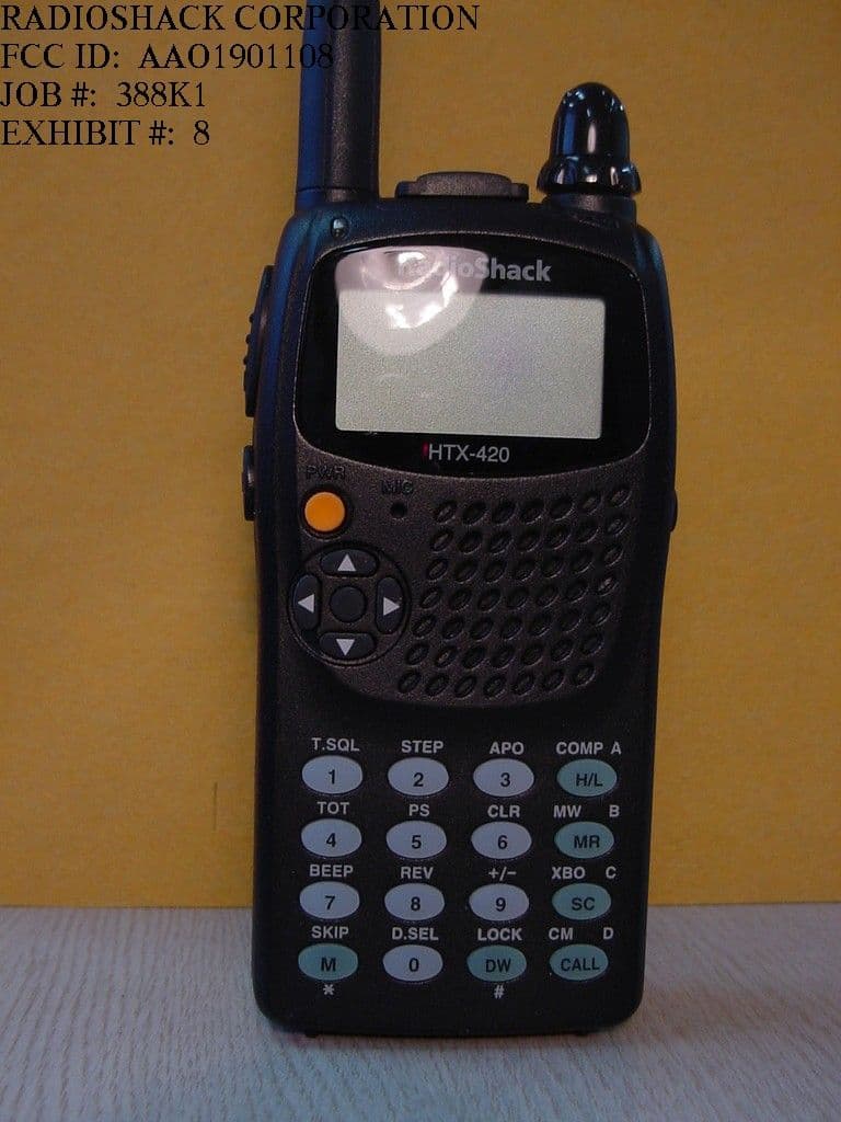
Click to zoom
Application Details
- Equipment Class
- CSR - Scanning Receiver
- Date of Grant
- May 31, 2001
- Application Purpose
- Original Equipment
- Date of Application
- May 31, 2001
- Equipment Note
- VHF/ UHF FM Handheld Transceiver
- Frequency Range
- 420.00000000 - 512.00000000
- Company
- RadioShack Corporation
- Country
- United States
Documents & Files
Document Text
Text extracted from the exhibit documents filed with the FCC. Open a document above to read the original.
Users Manual
BG TECH. VERSION III 2001/2/28 Cat. No. 19-1108 OWNER’S MANUAL Please read before using this equipment. HTX-420 Compact Handheld 2m/70cm FM Amateur Transceiver ® RadioShack® RADIOSHACK CORPORATION FCC ID: AAO1901108 JOB #: 388K1 EXHIBIT #: 4 BG TECH. VERSION III 2001/2/28 FEATURES Your RadioShack Compact Handheld 2m/70cm FM Amateur Transceiver is compact and rugged, making it easy to carry almost anywhere. The crystal controlled circuitry provides accurate and stable frequency selection, making it an ideal choice for your amateur communications needs. Note : You must have a Technician Class or higher Amateur Radio Operator’s License, and a call sign issued by the FCC, to legally transmit using this transceiver. Transmitting without a license carries heavy penalties. Getting a license is easier than ever. See “Introduction to Amateur Radio” on Page for more information. Here are some of your transceiver’s features. Delux-Featured Dual-Band Radio – means flexible transmitting options with the latest built-in conveniences. Its compact size and light weight are perfect for an amateur radio operation on the go. Full 16-Key DTMF (Dual-Tone Multi Frequency) Keypad – lets you dial and make telephone connections. Up To 5 Watts Output – The transceiver transmits at 5 output when powered by 13.8V External power supply. 100 Memory Locations – let you store up to 100 frequencies and other settings. S/RF and Battery Strength Meters – assure accurate signal and battery strength readings. CTCSS (Continuous Tone Coded Squelch System) Subaudible Tone – both encodes and decodes 50 subaudible tones to help reduce interference from other nearby systems operating on the same frequency. Repeater Offset – lets you select the offset value to match a local repeater. Scan – the transceiver scans its full frequency range and 100 memory locations for transmissions. BG TECH. VERSION III 2001/2/28 Power Save – conserves battery power when the transceiver is not transmitting or receiving. Programmable Frequency Steps – let you set the frequency increment for tuning or scanning to steps of 5, 6.25, 7.5, 10, 12.5, 15, 20, 25, 25, 50kHz. Signal Strength Indicator – a graduated bar shows the relative strength of the received signal. Time-Out Timer – lets you set a maximum transmission time interval among 1,2,3,4,5,10,15,20 minute. Earphone Jack and External Microphone Jack – let you connect an optional earphone, external microphone, or combination headset for more flexible operation. External Power Jack – lets you use an external power source for maximum output. Back Light – makes your transceiver easy to operate in low-light situations. Weather SAME Alert – lets you watch specific area message from NOAA and listen to the weather broadcast. Auto Power Off – lets your transceiver automatically turn off after a preset period of non-use. Electronic Compass – lets you know the directions. Cross Band Operation – lets you use the different frequency for transmitting and receiving. Dual Watch – let you watch two different channels. Air band receiver – lets you listen to air band broadcast. BG TECH. VERSION III 2001/2/28 MANUAL CONVENTIONS Your transceiver’s buttons perform multiple functions. The abbreviation or symbol for a function is printed on or above each button. To activate certain transceiver features, you must press F (function) and another button at the same time. Those key combination instructions are printed as the first button name, +, then the second button name. For example, F+ TOT means hold down F while you press TOT. Button names are printed in small, bold, capital letters such as CLR or MR. Words, symbols, and numbers that appear on the display are printed using a distinctive typeface, such as 146.940 or MR. FCC INFORMATION This device complies with Part 15 of the FCC Rules. Operation is subject to the following two conditions : (1) This device may not cause harmful interference, and (2) this device must accept any interference received, including interference that may cause undesired operation. BG TECH. VERSION III 2001/2/28 CONTENTS Introduction to Amateur Radio Preparation Using Internal Batteries Using Rechargeable Battery Pack Testing Internal Batteries Using Non-Rechargeable Batteries Using AC Power Using Vehicle Battery Power Connecting the Antenna Attaching the Belt Clip Attaching the Wrist Strap Connecting a Microphone/Speaker A Quick Look at the Display Operation Turning On/Off the Transceiver Changing the Channel/Frequency Up/Down Changing the Volume Up/Down Changing the Bands Using Monitor Button Using universal type e key for Set mode Repeater Operation Memory Operation Storing a Transmit/Receive Frequency (Memory Writing) Recalling Memory (Memory Reader) Checking Memory Location Settings Clearing a Single Memory Using the Calling Frequency Memory BG TECH. VERSION III 2001/2/28 Scanning Operation Scanning for Active Frequencies Continues Tone Coded Squelch System Features Using the CTCSS tones Using DTMF Code Transmitting a DTMF code from Memory Transmitting a DTMF Code Using Direct Entry Other Special Features Locking the Keypad Lighting the Display Turning the Display and Keypad Turning the Key Tone On and Off Setting the Frequency Step Power Save Using Auto Power Off Time-Out-Timer Turing the Weather Radio Frequencies Weather SAME Alert Electronic Compass TX Power Output Setting Busy Channel Lock Out Resetting XBO Channel Operation Dual Watch Receiving Air band Expanding TX Frequency range by Key pad Programming BG TECH. VERSION III 2001/2/28 INTRODUCTION TO AMATEUR RADIO Your transceiver is the perfect first radio for anyone entering the exciting world of amateur radio, s well as a great additional transceiver for the experienced amateur radio operator. Your transceiver opens a door for you to the world from almost anywhere! All you need is an Amateur Radio Operator’s License (Technician Class or higher) issued by the Federal Communications Commission (FCC). If you do not have a license, it is …
Text truncated - open the document above for the full version.
Attestation Statements
BG TECH F3 DONGIL BLDG. # 107 YANGJAE-DONG, SEOCHO-KU, SEOUL, KOREA TEL : 82-2-3497-6938 FAX : 82-2-574-0617 CONFIRMATION STATEMENT DATE : MAY 26, 2001 Federal Communications Commission Authorization and Evaluation Division 7435 Oakland Mills Road Columbia, MD 21046 To Whom It May Concern : We the undersigned, here by confirm that model No. HTX-420 (FCC ID : AAO1901108) is incapable of operation (tuning), or readily being altered by the user to operate, within the frequency bands allocated to the Domestic Public Cellular Radio Telecommunications Service in part 22 of this chapter (cellular telephone bands) as below reasons. Frequency generation is PLL type so that frequency shall be tuned / controlled by CPU. Current CPU has no capability to cover cellular frequencies. Even if CPU is changed to receive cellular frequencies, VCO cannot cover cellular frequencies. Therefore, even if a user modified or changed CPU or Filter, this unit still remains the state in which the unit cannot receive any cellular frequencies. Sincerely Yours, BG TECH YK Jung Y.K.JUNG/MANAGER
ID Label/Location Info
A. FCC MARKING/LABEL FOR PART 15 FCC ID : AAO1901108 Brand Name : RadioShack MODEL NO.: HTX-420 THIS DEVICE COMPLIES WITH PART 15 OF THE FCC RULES. OPERATION IS SUBJECT TO THE FOLLOWING TWO CONDITIONS: (1) THIS DEVICE MAY NOT CAUSE HARMFUL INTERFERENCE, AND (2) THIS DEVICE MUST ACCEPT ANY INTERFERENCE RECEIVED, INCLUDING INTERFERENCE THAT MAY CAUSE UNDESIRED OPERATION. RADIOSHACK CORPORATION FCC ID: AAO1901108 JOB #: 388K1 EXHIBIT #: 5
Test Report
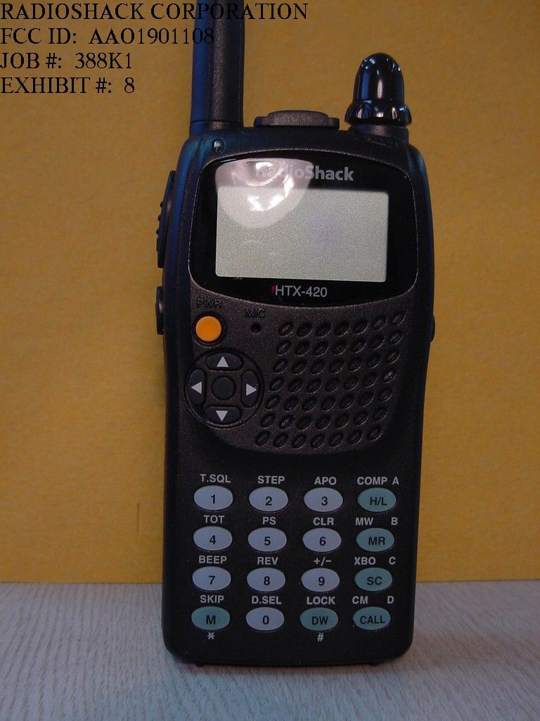
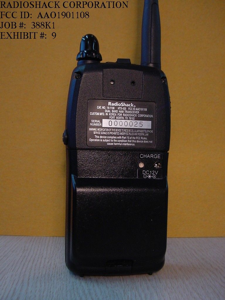
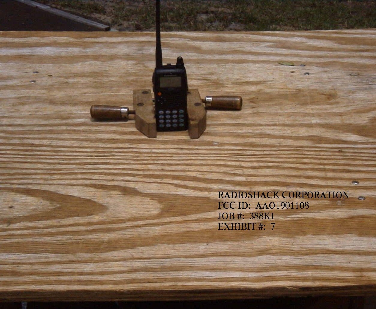
TABLE OF CONTENTS LIST APPLICANT: RADIOSHACK CORPORATION FCC ID: AAO1901108 TEST REPORT CONTAINING: PAGE 1......TEST PROCEDURE PAGE 2......TEST PROCEDURE & CIRCUIT DESCRIPTION PAGE 3-4....RADIATION INTERFERENCE TEST DATA PAGE 5......38 dB Rejection Ratio EXHIBITS CONTAINING: EXHIBIT 1............STATEMENT PER 15.121(a) EXHIBIT 2A-2B........BLOCK DIAGRAMS EXHIBIT 3A-3B........SCHEMATICS EXHIBIT 4............INSTRUCTION MANUAL EXHIBIT 5............SAMPLE OF FCC ID LABEL EXHIBIT 6............SKETCH OF LOCATION EXHIBIT 7............RADIATED TEST SETUP PHOTOGRAPH EXHIBIT 8............EXTERNAL PHOTO - FRONT SIDE EXHIBIT 9............EXTERNAL PHOTO - BACK SIDE EXHIBIT 10A-10D......INTERNAL PHOTOS - COMPONENT SIDE EXHIBIT 11A-11D......INTERNAL PHOTOS - COPPER SIDE EXHIBIT 12...........CIRCUIT DESCRIPTION APPLICANT: RADIOSHACK CORPORATION FCC ID: AAO1901108 REPORT #: R\RADSHACK\388K1\388K1RPT.doc PAGE: TABLE OF CONTENTS LIST APPLICANT: RADIOSHACK CORPORATION FCC ID: AAO1901108 TEST EQUIPMENT LIST 1._X_Spectrum Analyzer: HP 8566B-Opt 462, S/N 3138A07786, w/ preselector HP 85685A, S/N 3221A01400, Quasi-Peak Adapter HP 8565OA, S/N 3303A01690 & Preamplifier HP 8449B-OPT H02, S/N 3008A00372 Cal. 1/19/01 2._X_Biconnical Antenna: Eaton Model 94455-1, S/N 1057, Cal 3/15/00 3.___Biconnical Antenna: Electro-Metrics Model BIA-25, S/N 1171 Cal. 3/16/01 4._X_Log-Periodic Antenna: Electro-Metrics Model EM-6950, S/N 632 Cal. 3/15/00 5.___Log-Periodic Antenna: Electro-Metrics Model LPA-30, S/N 409 Cal. 3/15/00 6._X_Double-Ridged Horn Antenna: Electro-Metrics Model RGA-180, 1-18 GHz, S/N 2319 7.___18-26.3GHz Systron Donner Standard Gain Horn #DBE-520-20 8.___Horn 40-60GHz: ATM Part #19-443-6R 9.___Line Impedance Stabilization Network: Electro-Metrics Model EM-7820, w/NEMA Adapter S/N 2682 Cal. 3/16/01 10.___Temperature Chamber: Tenney Engineering Model TTRC, S/N 11717-7 Cal. 1/21/01 11.___Frequency Counter: HP Model 5385A, S/N 3242A07460 Cal 11/20/00 12.___Peak Power Meter: HP Model 8900C, S/N 2131A00545, Cal. 1/26/01 13._X_Open Area Test Site #1-3meters Cal. 12/22/99 14.___Signal Generator: HP 8640B, S/N 2308A21464 Cal. 11/21/00 15.___Signal Generator: HP 8614A, S/N 2015A07428 16.___Passive Loop Antenna: EMCO Model 6512, 9KHz to 30MHz, S/N 9706-1211 Cal. 6/10/00 17.___Dipole Antenna Kit: Electro-Metrics Model TDA-30/1-4, S/N 153 Cal. 11/24/00 18.___AC Voltmeter: HP Model 400FL, S/N 2213A14499 Cal. 2/1/01 19.___Digital Multimeter: Fluke Model 8012A, S/N 4810047 Cal 9/21/99 20.___Digital Multimeter: Fluke Model 77, S/N 43850817 Cal 11/16/00 21.___Oscilloscope: Tektronix Model 2230, S/N 300572 Cal 2/1/01 TEST PROCEDURE GENERAL: This report shall NOT be reproduced except in full without the written approval of TIMCO ENGINEERING, INC. RADIATION INTERFERENCE: The test procedure used was ANSI STANDARD C63.4-1992 using a HEWLETT PACKARD spectrum analyzer with a prese- lector. The bandwidth of the spectrum analyzer was 100 kHz with an appropriate sweep speed. The analyzer was calibrated in dB above a microvolt at the output of the antenna. The resolution bandwidth was 100KHz and the video bandwidth was 300KHz. The ambient temperature of the UUT was 80ºC with a humidity of 76%. APPLICANT: RADIOSHACK CORPORATION FCC ID: AAO1901108 REPORT #: R\RADSHACK\388K1\388K1RPT.doc PAGE #: 1 APPLICANT: RADIOSHACK CORPORATION FCC ID: AAO1901108 TEST PROCEDURES CONTINUED FORMULA OF CONVERSION FACTORS: The Field Strength at 3m was estab- lished by adding the meter reading of the spectrum analyzer (which is set to read in units of dBuV) to the antenna correction factor sup- plied by the antenna manufacturer. The antenna correction factors are stated in terms of dB. The gain of the Preselector was accounted for in the Spectrum Analyzer Meter Reading. Example: Freq (MHz) METER READING + ACF = FS 33 20 dBuV + 10.36 dB = 30.36 dBuV/m @ 3m ANSI STANDARD C63.4-1992 10.1.7 MEASUREMENT PROCEDURES: The unit under test was placed on a table 80 cm high and with dimensions of 1m by 1.5m. The table used for radiated measurements is capable of continu- ous rotation. When an emission was found, the table was rotated to produce the maximum signal strength. At this point, the antenna was raised and lowered from 1m to 4m. The antenna was placed in both the horizontal and vertical planes. APPLICANT: RADIOSHACK CORPORATION FCC ID: AAO1901108 REPORT #: R\RADSHACK\388K1\388K1RPT.doc PAGE #: 2 APPLICANT: RADIOSHACK CORPORATION FCC ID: AAO1901108 NAME OF TEST: RADIATION INTERFERENCE RULES PART NUMBER: 15.109 REQUIREMENTS: 30 to 80 MHz: 40.0 dBuV/M @ 3 METERS 88 to 216 MHz: 43.5 dBuV/M 216 to 960 MHz: 46.0 dBuV/M ABOVE 960 MHz: 54.0 dBuV/M TEST RESULTS: A search was made of the spectrum from 30 to 1000 MHz and the measurements indicate that the unit DOES meet the FCC requirements. TEST DATA: Tuned Frequency MHz Emission Frequency MHz Meter Reading dBuv Coax Loss dB Correction Factor dB Field Strenth dBuv/m Margin dB Antenna Polarity 110.60 155.60 7.00 0.90 16.73 24.63 18.87 H 110.60 311.20 5.70 1.40 15.30 22.40 23.60 V 110.60 466.80 9.40 1.60 18.54 29.54 16.46 V 120.60 165.60 6.50 0.90 17.72 25.12 18.38 H 120.60 496.80 9.40 1.60 19.23 30.23 15.77 V 120.60 662.47 6.30 2.00 21.47 29.77 16.23 H 135.60 180.60 5.30 0.90 14.69 20.89 22.61 H 135.60 361.20 7.50 1.40 15.87 24.77 21.23 V 135.60 722.30 6.00 2.00 21.94 29.94 16.06 H 420.00 374.90 21.90 1.40 16.27 39.57 6.43 V 420.00 749.80 9.70 2.00 21.90 33.60 12.40 H 420.00 1499.60 12.90 1.00 26.00 39.90 14.10 V 466.00 420.90 13.80 1.60 17.48 32.88 13.12 V 466.00 1262.00 10.40 1.00 25.05 36.45 17.55 V 466.00 1683.60 12.20 1.00 26.73 39.93 14.07 V 512.00 466.90 9.20 1.60 18.54 29.34 16.66 V 512.00 933.80 10.30 2.90 24.17 37.37 8.63 V 512.00 1400.70 16.80 1.00 25.60 43.40 10.60 V 512.00 1868.00 6.80 1.01 27.47 35.28 18.72 H 162.50 207.43 5.60 1.20 12.14 18.94 24.56 H 162.50 414.90 5.50 1.60 17.34 24.44 21.56 V 162.50 622.30 6.20 1.60 20.59 28.39 17.61 H 137.00 364.00 7.50 1.40 15.96 24.86 21.14 V 137.00 546.00 4.40 1.60 19.6…
Text truncated - open the document above for the full version.
Contact Information
Applicant
Elizabeth Granados(Regulatory Affairs Manager)
Test Firm
Timco Engineering, Inc.S Sanders
Technical Specifications
| # | Rule Parts | Frequency Range | Power Output |
|---|---|---|---|
| 2 | 15B | 420 MHz - 512 MHz | - |
Other Applications from RadioShack Corporation

AAO2302500
Feb 10, 2015Bluetooth Power Bank
Equipment Class
DXX - Part 15 Low Power Communication Device Transmitter
AAO4300124C
May 02, 2013900MHz Wireless Intercom
Equipment Class
DXT - Part 15 Low Power Transceiver, Rx Verified
AAO1200876
Nov 30, 2011Universal FM Transmitter
Equipment Class
DXX - Part 15 Low Power Communication Device Transmitter
AAO1200962
Aug 02, 2011Universal FM Transmitter
Equipment Class
DXX - Part 15 Low Power Communication Device Transmitter
AAO1500044T
Apr 02, 20112.4GHz Digital Wireless Rear Speaker Kit - Transmitter
Equipment Class
DSS - Part 15 Spread Spectrum Transmitter