AAO1901208Business Band Transceiver
RadioShack Corporation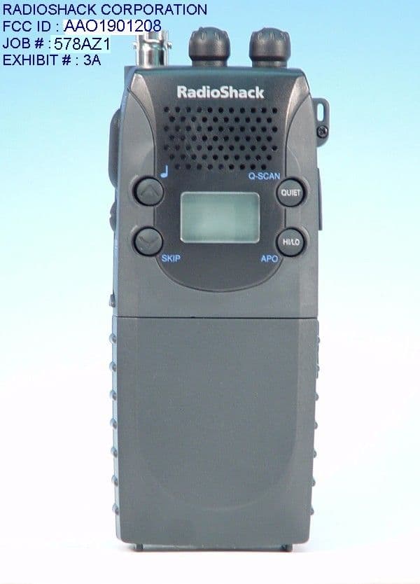
Click to zoom
Application Details
- Equipment Class
- TNF - Licensed Non-Broadcast Transmitter Held to Face
- Date of Grant
- Jun 19, 2001
- Application Purpose
- Original Equipment
- Date of Application
- May 07, 2001
- Equipment Note
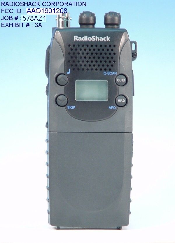
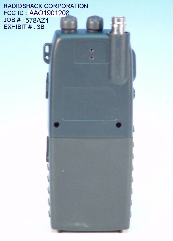
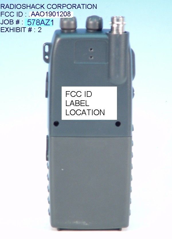
- Business Band Transceiver
- Frequency Range
- 464.50000000 - 467.92500000
- Company
- RadioShack Corporation
- Country
- United States
Documents & Files
Document Text
Text extracted from the exhibit documents filed with the FCC. Open a document above to read the original.
Users Manual
1 OWNER’S MANUAL 19-1208 INTRODUCTION Your Radio Shack 19-1208 Business band transceiver is a portable, easy-to-use, two-way radio that you can carry almost anywhere. It is approved with commercial-grade standards to give you clear, reliable communication. This transceiver consists of 8 Business channels. Your 19-1208 provides for personal communications with family members or other licenses. You can use the 19-1208 for recreational communications while you hike, ski, or fish. You can even use the 19-1208 to coordinates your personal or business activities with other family members. When you get a license to operate the radio, you can let other members of your family living in the same household operate the radio. Your transceiver has the following features: PLL-Controlled Circuitry ---- provides accurate and stable channel selection. Adjustable Squelch ---- helps eliminate noise between transmissions. 38 CTCSS (Continuous Tone Control Squelch System) ---- helps reduce interference from other systems in the area operating on the same frequency. Built-in Modulation Limiter Circuit ---- automatically adjusts for a wide variety of voice levels to ensure an understandable transmission. High/Low Power ---- lets you save power by selecting a suitable transmitting power for long or short distances. Battery Low and Transmit Indicator ---- shows the battery pack’s condition and lights when you transmit or receive. Removable and Rechargeable Battery Pack ---- lets you use one battery pack while you charge another (additional packs available). Supplied Battery Charger ---- conveniently recharges your transceiver’s battery pack. Flexible Antenna with BNC Connector ---- provides excellent reception. The BNC connector is designed so you can easily attach and remove the supplied antenna or an optional one. Earphone Jack and External Microphone Jack ---- let you use an earphone or external microphone to help ensure understandable communications in noisy areas. Belt Clip ---- lets you attach the transceiver to your belt or waistband. JIS level 4 ---- provides excellent waterproof capability. RADIOSHACK CORP. FCC ID : AAO1901208 JOB # : 578ZA1 EXHIBIT # : 6 2 We recommend you record your transceiver’s serial number here. This number is on the transceiver’s back panel. Serial Number_______________________ FCC Information FCC License required This Transceiver is intended for use in the operation of commercial activities, in educational, philanthropic, or ecclesiastical institutions, and hospitals, clinics, or medical associations. The Federal Communications commission (FCC)requires you to be licensed before you operate this transceiver. Unless you are already licensed to operate on one of the preset frequencies, you must apply for a frequency through the PCIA (Personal Communication Industry Association), a non-profit organization that assigns frequencies nationwide to help prevent conflicts between different businesses using transceivers in the same area. For more information about getting a license, contact the PCIA at 800-759-0300, extension 3068 (in Virginia 703-739-0300, extension 3068) For other questions concerning the license application, contact the FCC at 717-337-1212, or wirte: FCC P.O.Box 1040 Gettysburg, PA 17325 For the latest FCC application form and instructions, call the FCC’s fax-on-demand service at 1-202-418-0177 from a fax machine and request one or more of the following documents: All forms and instructions ........................000600 Form 600 instructions only........................006001 Main Form 600 only.................................006002 Form 600 schedules only...........................006003 If you do not have a fax machine, you can call the Government Forms Distribution Center at 1-800-418-FORM and request that the form and instructions be mailed to you. FCC Part 90 Rules You must be familiar with Part 90 of FCC Rules before you operate your transceiver. The 3 operation instructions in this manual conform to Part 90, but do not cover all items in Part 90. Overall, Part 90 states that: ! You must have a valid license before you use the transceiver. ! As licensee, you are responsible for proper operation of all transceivers operating under your license’s authority. ! You can let unlicensed persons operate transmitter, as long as you take precautions to prevent unauthorized transmissions. ! You must use this transceiver only for commercial use of your business, and only when other commercial channels (such as the telephone) are either not available or not practical. ! You must always yield the operating frequency to communications that involve the safety of life or property. ! You must take reasonable precautions to prevent harmful interference to other services operating on the same frequency. ! You must not transmit program material of any kind used in connection with commercial broadcasting. ! You must not provide a service that is normally handles by telephone or telegraph unless such broadcasts involve the safety of life and property or in emergencies such as an earthquake, hurricane, flood or a similar disaster where normal communications channels are disrupted. ! During each transmissions or exchange of transmissions, you must identify your station with the call sign issued to you by the FCC, or once each 15 minutes during periods of continuous operation. ! You must keep a written record of any maintenance or modifications made to the transceiver, and you must make this record available for inspection upon demand by the FCC. Violating any of the provisions of Part 90 can result in fines and/or confiscation of equipment. Your transceiver might cause TV or Radio interference even when it is operating properly. To determine whether your transceiver is causing the interference, turn off your transceiver. If the interference goes away, your transceiver us causing it. Try to eliminate the interference by: ! Moving your transceiver away from the receiver ! Contacting your …
Text truncated - open the document above for the full version.
Cover Letter(s)
TIMCO ENGINEERING, INC. P.O. BOX 370 849 N.W. STATE ROAD 45 NEWBERRY, FL 32669 PHONE: 888-472-2424 OR 352-472-5500 FAX: 352-472-2030 EMAIL: [email protected] June 20, 2001 Mr. Richard Fabina Federal Communications Commission Authorization and Evaluation Division 7435 Oakland Mills Road Columbia, MD 21046 Ref: RadioShack Corporation’s FCC ID: AAO1901208 Confirmation # EA100908 Dear Mr. Fabina: On May 8, 2001, we submitted an application for approval for the above mentioned FCC Identifier. The application was granted on 6/14/01 and upon notification of the application being granted, RadioShack obtained a copy of the grant of certification from the FCC web site. They noticed that the high output power was listed as 2.5 Watt and they contacted us to ask why it was not approved as 5.0 Watt. We then reviewed our report and realized that we made an error on the 731 form and the report that we did not catch before submitting the application. When we originally received the sample for testing, the output power was in fact 2.5 Watts. The manufacturer did not wish to have approval of 2.5 Watts so they had modified the sample and sent it to us for retested and we obtained the 5.0 Watts. When we submitted the application, the radiated data is from the 5.0 Watt radio but the antenna conducted data is from the 2.5 Watt radio. I’ve corrected the pages of the report which were incorrect and have attached those for your review. My question to you is this – since the grant was issued less than 30 days, can we send the corrected test report to you so that it can be granted as a 5.0 Watt instead of 2.5 Watt radio? Regards, Mario R. de Aranzeta Engineer
Schematics
RADIOSHACK CORPORATIONFCC ID : AAO1901208EXHIBIT # : 5
Test Report
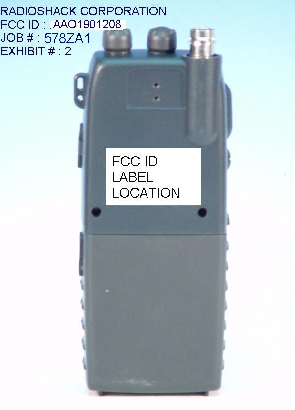
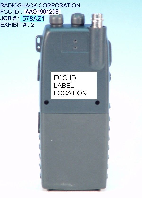
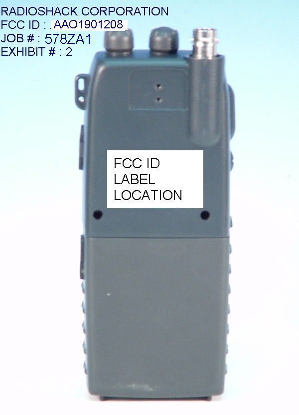
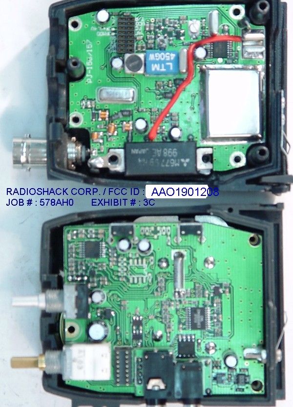
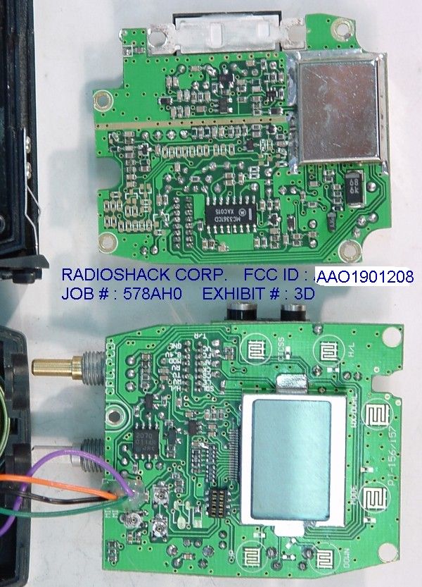
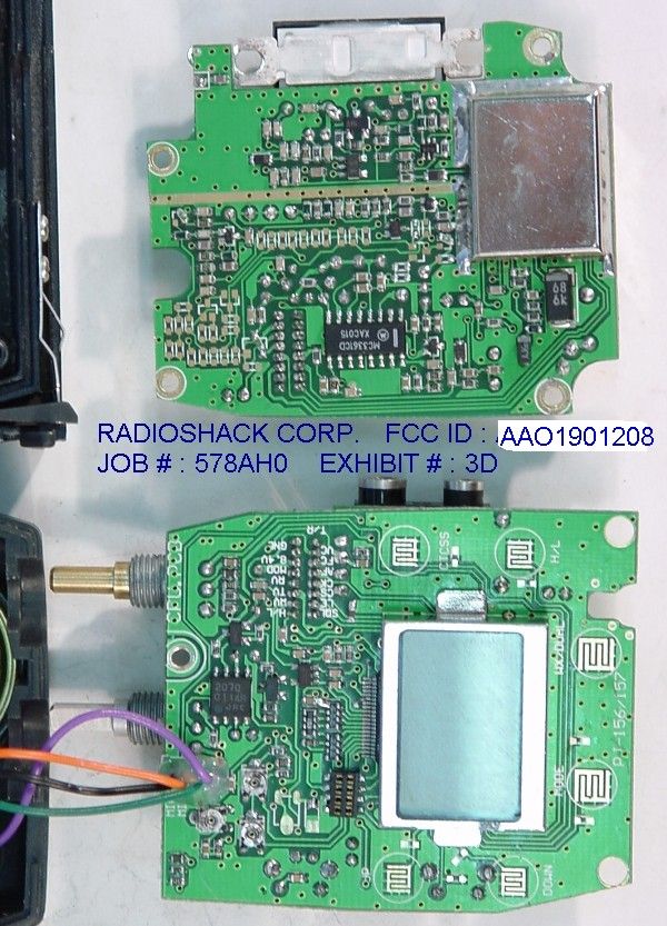
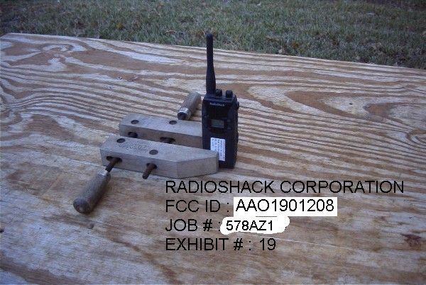
TABLE OF CONTENTS LIST APPLICANT: RADIOSHACK CORPORATION FCC ID: AAO1901208 TEST REPORT: PAGE 1......COVER SHEET - GENERAL INFORMATION & TECHNICAL DESCR. PAGE 2......TECHNICAL DESCRIPTION CONTD. & RF POWER OUTPUT PAGE 3......MODULATION CHARACTERISTICS & OCCUPIED BANDWIDTH PAGE 4......OCCUPIED BANDWIDTH PAGE 5......SPURIOUS EMISSIONS AT ANTENNA TERMINALS PAGE 6......FIELD STRENGTH OF SPURIOUS EMISSIONS PAGE 7-8....FREQUENCY STABILITY PAGE 9......TRANSIENT FREQUENCY STABILITY PAGE 10.....LIST OF TEST EQUIPMENT EXHIBITS CONTAINING: EXHIBIT 1.........FCC ID LABEL SAMPLE EXHIBIT 2.........SKETCH OF LABEL LOCATION EXHIBIT 3A........EXTERNAL PHOTO - FRONT VIEW EXHIBIT 3B........EXTERNAL PHOTO - REAR VIEW EXHIBIT 3C........INTERNAL PHOTO - COMPONENT VIEW EXHIBIT 3D........INTERNAL PHOTO - COPPER VIEW EXHIBIT 4.........BLOCK DIAGRAM EXHIBIT 5.........SCHEMATIC EXHIBIT 6.........USER'S MANUAL EXHIBIT 7A-7B.....OPERATIONAL DESCRIPTION EXHIBIT 8A-C......TUNING PROCEDURE EXHIBIT 9.........AUDIO LOW PASS FILTER EXHIBIT 10........MODULATION LIMITING 300 Hz EXHIBIT 11........MODULATION LIMITING 1000 Hz EXHIBIT 12........MODULATION LIMITING 3000 Hz EXHIBIT 13........AUDIO FREQUENCY RESPONSE GRAPH EXHIBIT 14A-B.....CRYSTAL SPECIFICATIONS EXHIBIT 15........OCCUPIED BANDWIDTH PLOT - CW EXHIBIT 16........OCCUPIED BANDWIDTH EXHIBIT 17A.......LOW POWER TRANSIENT FREQUENCY RESPONSE EXHIBIT 17B.......LOW POWER TRANSIENT FREQUENCY RESPONSE EXHIBIT 18A.......HIGH POWER TRANSIENT FREQUENCY RESPONSE EXHIBIT 18B.......HIGH POWER TRANSIENT FREQUENCY RESPONSE EXHIBIT 19........TEST SET UP PHOTO APPLICANT: RADIOSHACK CORPORATION FCC ID: AAO1901208 DATE: MAY 3, 2001 REPORT #: T:\CUS\R\RADSHACK\578AZ1\578AZ1TESTRPT.DOC PAGE: TABLE OF CONTENTS GENERAL INFORMATION REQUIRED FOR TYPE ACCEPTANCE 2.1033 (C)(1)(2) RADIOSHACK CORPORATION will sell the FCCID: AAO1901208 UHF BUSINESS BAND transciever in quantity, for use under FCC RULES PART 22, 90 RADIOSHACK CORPORATION 100 THROCKMORTON STREET SUITE 1300 FT. WORTH, TX 76102-2802 U.S.A. 2.1033(C)(3) A copy of the instruction manual is included as Exhibit 6. (4) ALLOWED AUTHORIZED BANDWIDTH = 11.25kHz. 90.209(b)(5) Bn = 2M + 2DK M = 3000 D = 2625 (Peak Deviation) K = 1 Bn = 2(3.0K) + 2(2625)(1) = 6.0K + 5250 = 11.25 K Type of Emission: 11K25F3E 2.1033(C)(5) Frequency Range: 464.5000-467.9250 MHz (6) Power Range and Controls: This UUT has two (2) power ranges, 1.0 and 2.5 watts (7) Maximum Power Rating: 2.5 Watts into a 50 ohm resistive load. (8) DC Voltages and Current Final Amplifier: FINAL AMPLIFIER ONLY Vce = 8.4 Volts DC Ice = 0.92A Pin = 7.70 Watts (9) The tuning procedure is included as Exhibit 8A-8C. (10) A schematic in included in Exhibit 5. (11) Photograph or drawing of the label showing the FCC ID and the location of the label is shown in Exhibits 1 and 2. APPLICANT: RADIOSHACK CORPORATION FCC ID: AAO1901208 DATE: MAY 3, 2001 REPORT #: T:\CUS\R\RADSHACK\578AZ1\578AZ1TESTRPT.DOC PAGE #: 1 2.1033(c)(12) Photographs completely documenting the radio are shown in Exhibits 3A-3D. 2.1033(c)(13) N/A This is for devices that use digital modulation. 2.1033(c)(14) The data required by 2.1046 through 2.1057 follows; 2.1046(a) RF power output. The test procedure used was TIA/EIA-603 S2.2.1. RF power is measured by connecting a 50 ohm, resistive wattmeter to the RF output connector. With a nominal battery voltage of 8.4V, and the transmitter properly adjusted the RF output measures: INPUT POWER: (8.4V)(0.9A) = 7.7Watts OUTPUT POWER: 2.5 Watts Efficiency: 32% INPUT POWER(MED): (8.4V)(0.4) = 3.36 Watts OUTPUT POWER(LO): 1.0 Watts Effeciency: 29% 2.1046(a) RF power output. The test procedure used was TIA/EIA-603 S2.2.1. DUMMY MICROPHONE STANDARD RF TRANSMITTER TRANSMITTER POWER UNDER TEST LOAD METER APPLICANT: RADIOSHACK CORPORATION FCC ID: AAO1901208 DATE: MAY 3, 2001 REPORT #: T:\CUS\R\RADSHACK\578AZ1\578AZ1TESTRPT.DOC PAGE #: 2 2.1047(a) Modulation characteristics: AUDIO FREQUENCY RESPONSE The audio frequency response was measured in accordance with TIA/EIA Specification TIA/EIA-603 S2.2.6.2.1. The audio frequency response curve is shown in Exhibit 13. 2.1049 AUDIO LOW PASS FILTER Transmitters utilizing analog emissions and meets the requirements of paragraph 90.210(b)&(c) and the plot of the post limiter filter is included as Exhibit #9. . 2.1049 AUDIO INPUT VERSUS MODULATION The audio frequency input versus deviation was measured in accordance with TIA/EIA Specification 603 S2.2.6.2.1. with the follow- ing exceptions; starting with 1000Hz the input was increased well beyond the deviation changing. This measurement was repeated for the band limits and any frequency deemed appropriate. See Exhibits 10-12. DUMMY AUDIO RMS MICROPHONE GENERATOR VOLTMETER STANDARD TEST TRANSMITTER TRANSMITTER RECEIVER UNDER TEST PROBE 1.The test receiver audio bandwidth was <50Hz to >20,000Hz. 2.1049 Occupied bandwidth: 90.210 (d) (1) On any frequency from the center of the authorized Bandwidth f 0 to 5.625 kHz removed from f 0 : Zero dB. (2) On any frequency removed from the center of the authorized bandwidth by a displacement frequency (f d in kHz) of more than 5.625 kHz but no more than 12.5 kHz: At least 7.27(f d – 2.88 kHz) dB. (3) On any frequency removed from the center of the authorized bandwidth by a displacement frequency (f d in kHz) of more than 12.5: At least 50 + 10 log (P) dB or 70 dB, whichever is the lesser attenuation. APPLICANT: RADIOSHACK CORPORATION FCC ID: AAO1901208 DATE: MAY 3, 2001 REPORT #: T:\CUS\R\RADSHACK\578AZ1\578AZ1TESTRPT.DOC PAGE #: 3 2.1049 Occupied bandwidth: 90.210 (d) 2 Requirement For 12.5 kHz channel bandwidth equipment, any emission must be attenuated below the power (P) of the highest emission contained within the authorized bandwidth as follows; (1) On any frequency from the center of the authorized bandwidth f0: Zero dB. (2) On any frequency removed from the center of the authorized bandwidth by a displacement frequency (fdd kHz) of more than 5.625kHz but no more …
Text truncated - open the document above for the full version.
Test Report
TABLE OF CONTENTS LIST APPLICANT: RADIOSHACK CORPORATION FCC ID: AAO1901208 TEST REPORT: PAGE 1......COVER SHEET - GENERAL INFORMATION & TECHNICAL DESCR. PAGE 2......TECHNICAL DESCRIPTION CONTD. & RF POWER OUTPUT PAGE 3......MODULATION CHARACTERISTICS & OCCUPIED BANDWIDTH PAGE 4......OCCUPIED BANDWIDTH PAGE 5......SPURIOUS EMISSIONS AT ANTENNA TERMINALS PAGE 6......FIELD STRENGTH OF SPURIOUS EMISSIONS PAGE 7-8....FREQUENCY STABILITY PAGE 9......TRANSIENT FREQUENCY STABILITY PAGE 10.....LIST OF TEST EQUIPMENT EXHIBITS CONTAINING: EXHIBIT 1.........FCC ID LABEL SAMPLE EXHIBIT 2.........SKETCH OF LABEL LOCATION EXHIBIT 3A........EXTERNAL PHOTO - FRONT VIEW EXHIBIT 3B........EXTERNAL PHOTO - REAR VIEW EXHIBIT 3C........INTERNAL PHOTO - COMPONENT VIEW EXHIBIT 3D........INTERNAL PHOTO - COPPER VIEW EXHIBIT 4.........BLOCK DIAGRAM EXHIBIT 5.........SCHEMATIC EXHIBIT 6.........USER'S MANUAL EXHIBIT 7A-7B.....OPERATIONAL DESCRIPTION EXHIBIT 8A-C......TUNING PROCEDURE EXHIBIT 9.........AUDIO LOW PASS FILTER EXHIBIT 10........MODULATION LIMITING 300 Hz EXHIBIT 11........MODULATION LIMITING 1000 Hz EXHIBIT 12........MODULATION LIMITING 3000 Hz EXHIBIT 13........AUDIO FREQUENCY RESPONSE GRAPH EXHIBIT 14A-B.....CRYSTAL SPECIFICATIONS EXHIBIT 15........OCCUPIED BANDWIDTH PLOT - CW EXHIBIT 16........OCCUPIED BANDWIDTH EXHIBIT 17A.......LOW POWER TRANSIENT FREQUENCY RESPONSE EXHIBIT 17B.......LOW POWER TRANSIENT FREQUENCY RESPONSE EXHIBIT 18A.......HIGH POWER TRANSIENT FREQUENCY RESPONSE EXHIBIT 18B.......HIGH POWER TRANSIENT FREQUENCY RESPONSE EXHIBIT 19........TEST SET UP PHOTO APPLICANT: RADIOSHACK CORPORATION FCC ID: AAO1901208 DATE: MAY 3, 2001 REPORT #: T:\CUS\R\RADSHACK\578AZ1\578AZ1TESTRPT.DOC PAGE: TABLE OF CONTENTS GENERAL INFORMATION REQUIRED FOR TYPE ACCEPTANCE 2.1033 (C)(1)(2) RADIOSHACK CORPORATION will sell the FCCID: AAO1901208 UHF BUSINESS BAND transciever in quantity, for use under FCC RULES PART 22, 90 RADIOSHACK CORPORATION 100 THROCKMORTON STREET SUITE 1300 FT. WORTH, TX 76102-2802 U.S.A. 2.1033(C)(3) A copy of the instruction manual is included as Exhibit 6. (4) ALLOWED AUTHORIZED BANDWIDTH = 11.25kHz. 90.209(b)(5) Bn = 2M + 2DK M = 3000 D = 2625 (Peak Deviation) K = 1 Bn = 2(3.0K) + 2(2625)(1) = 6.0K + 5250 = 11.25 K Type of Emission: 11K25F3E 2.1033(C)(5) Frequency Range: 464.5000-467.9250 MHz (6) Power Range and Controls: This UUT has two (2) power ranges, 1.0 and 2.5 watts (7) Maximum Power Rating: 2.5 Watts into a 50 ohm resistive load. (8) DC Voltages and Current Final Amplifier: FINAL AMPLIFIER ONLY Vce = 8.4 Volts DC Ice = 0.92A Pin = 7.70 Watts (9) The tuning procedure is included as Exhibit 8A-8C. (10) A schematic in included in Exhibit 5. (11) Photograph or drawing of the label showing the FCC ID and the location of the label is shown in Exhibits 1 and 2. APPLICANT: RADIOSHACK CORPORATION FCC ID: AAO1901208 DATE: MAY 3, 2001 REPORT #: T:\CUS\R\RADSHACK\578AZ1\578AZ1TESTRPT.DOC PAGE #: 1 2.1033(c)(12) Photographs completely documenting the radio are shown in Exhibits 3A-3D. 2.1033(c)(13) N/A This is for devices that use digital modulation. 2.1033(c)(14) The data required by 2.1046 through 2.1057 follows; 2.1046(a) RF power output. The test procedure used was TIA/EIA-603 S2.2.1. RF power is measured by connecting a 50 ohm, resistive wattmeter to the RF output connector. With a nominal battery voltage of 8.4V, and the transmitter properly adjusted the RF output measures: INPUT POWER: (8.4V)(0.9A) = 7.7Watts OUTPUT POWER: 2.5 Watts Efficiency: 32% INPUT POWER(MED): (8.4V)(0.4) = 3.36 Watts OUTPUT POWER(LO): 1.0 Watts Effeciency: 29% 2.1046(a) RF power output. The test procedure used was TIA/EIA-603 S2.2.1. DUMMY MICROPHONE STANDARD RF TRANSMITTER TRANSMITTER POWER UNDER TEST LOAD METER APPLICANT: RADIOSHACK CORPORATION FCC ID: AAO1901208 DATE: MAY 3, 2001 REPORT #: T:\CUS\R\RADSHACK\578AZ1\578AZ1TESTRPT.DOC PAGE #: 2 2.1047(a) Modulation characteristics: AUDIO FREQUENCY RESPONSE The audio frequency response was measured in accordance with TIA/EIA Specification TIA/EIA-603 S2.2.6.2.1. The audio frequency response curve is shown in Exhibit 13. 2.1049 AUDIO LOW PASS FILTER Transmitters utilizing analog emissions and meets the requirements of paragraph 90.210(b)&(c) and the plot of the post limiter filter is included as Exhibit #9. . 2.1049 AUDIO INPUT VERSUS MODULATION The audio frequency input versus deviation was measured in accordance with TIA/EIA Specification 603 S2.2.6.2.1. with the follow- ing exceptions; starting with 1000Hz the input was increased well beyond the deviation changing. This measurement was repeated for the band limits and any frequency deemed appropriate. See Exhibits 10-12. DUMMY AUDIO RMS MICROPHONE GENERATOR VOLTMETER STANDARD TEST TRANSMITTER TRANSMITTER RECEIVER UNDER TEST PROBE 1.The test receiver audio bandwidth was <50Hz to >20,000Hz. 2.1049 Occupied bandwidth: 90.210 (d) (1) On any frequency from the center of the authorized Bandwidth f 0 to 5.625 kHz removed from f 0 : Zero dB. (2) On any frequency removed from the center of the authorized bandwidth by a displacement frequency (f d in kHz) of more than 5.625 kHz but no more than 12.5 kHz: At least 7.27(f d – 2.88 kHz) dB. (3) On any frequency removed from the center of the authorized bandwidth by a displacement frequency (f d in kHz) of more than 12.5: At least 50 + 10 log (P) dB or 70 dB, whichever is the lesser attenuation. APPLICANT: RADIOSHACK CORPORATION FCC ID: AAO1901208 DATE: MAY 3, 2001 REPORT #: T:\CUS\R\RADSHACK\578AZ1\578AZ1TESTRPT.DOC PAGE #: 3 2.1049 Occupied bandwidth: 90.210 (d) 2 Requirement For 12.5 kHz channel bandwidth equipment, any emission must be attenuated below the power (P) of the highest emission contained within the authorized bandwidth as follows; (1) On any frequency from the center of the authorized bandwidth f0: Zero dB. (2) On any frequency removed from the center of the authorized bandwidth by a displacement frequency (fdd kHz) of more than 5.625kHz but no more …
Text truncated - open the document above for the full version.
Test Report
Relative Deviation (dB) RE: 19-1208 Please find below our test data for 19-1208 for Timco reference. Relative Deviation(dB) Modulation Frequency(Hz) 19-1208Limit 10000 25500.2 3000-0.30 4500-11.4-10.6 6000-24.2-18 9000-43.2-28.6 10000-59.5-31.4 12500-64-37.2 18000-64-46.7 25000-64-55.3 Best regards, Eileen -70 -65 -60 -55 -50 -45 -40 -35 -30 -25 -20 -15 -10 -5 0 5 1000255030004500600090001000125018002500 19-1208 Limit Freque ncy ( Hz) RADIOSHACK CORPORATION FCC ID : AAO1901208 JOB # : 578ZA1 EXHIBIT # : 9
Test Report
Relative Deviation (dB) RE: 19-1208 Please find below our test data for 19-1208 for Timco reference. Relative Deviation(dB) Modulation Frequency(Hz) 19-1208Limit 10000 25500.2 3000-0.30 4500-11.4-10.6 6000-24.2-18 9000-43.2-28.6 10000-59.5-31.4 12500-64-37.2 18000-64-46.7 25000-64-55.3 Best regards, Eileen -70 -65 -60 -55 -50 -45 -40 -35 -30 -25 -20 -15 -10 -5 0 5 1000255030004500600090001000125018002500 19-1208 Limit Freque ncy ( Hz) RADIOSHACK CORPORATION FCC ID : AAO1901208 JOB # : 578ZA1 EXHIBIT # : 9
Test Report
Modulation Limiting Radio Shack 19-1208 0 500 1000 1500 2000 2500 3000 3500 050100150200 rms mVolts Deviation 300 Hz RADIOSHACK CORPORATION FCC ID: AAO1901208 JOB #: 578AZ1 EXHIBIT #: 10
Test Report
Modulation Limiting Radio Shack 19-1208 0 500 1000 1500 2000 2500 010203040 rms mVolts Deviatio n 1000 Hz RADIOSHACK CORPORATION FCC ID : AAO1901208 JOB # : 578AZ1 EXHIBIT # 11
Test Report
Modulation Limiting Radio Shack 19-1208 0 500 1000 1500 2000 2500 3000 3500 0 1020304050 rms mVolts Deviation 3000 Hz RADIOSHACK CORPORATION FCC ID : AAO1901208 JOB # : 578AZ1 EXHIBIT # : 12
Test Report
Radio Shack 19-1208 0 10 20 30 40 50 60 100100010000 Freque ncy rms mVolts audio response RADIOSHACK CORPORATION FCC ID : AAO1901208 JOB # : 578AZ1 EXHIBIT # : 13
Test Report
GENERAL INFORMATION REQUIRED FOR TYPE ACCEPTANCE 2.1033 (C)(1)(2) RADIOSHACK CORPORATION will sell the FCCID: AAO1901208 UHF BUSINESS BAND transciever in quantity, for use under FCC RULES PART 22, 90 RADIOSHACK CORPORATION 100 THROCKMORTON STREET SUITE 1300 FT. WORTH, TX 76102-2802 U.S.A. 2.1033(C)(3) A copy of the instruction manual is included as Exhibit 6. (4) ALLOWED AUTHORIZED BANDWIDTH = 11.25kHz. 90.209(b)(5) Bn = 2M + 2DK M = 3000 D = 2625 (Peak Deviation) K = 1 Bn = 2(3.0K) + 2(2625)(1) = 6.0K + 5250 = 11.25 K Type of Emission: 11K25F3E 2.1033(C)(5) Frequency Range: 464.5000-467.9250 MHz (6) Power Range and Controls: This UUT has two (2) power ranges, 1.0 and 5.0 watts (7) Maximum Power Rating: 5.0 Watts into a 50 ohm resistive load. (8) DC Voltages and Current Final Amplifier: FINAL AMPLIFIER ONLY Vce = 8.4 Volts DC Ice = 0.92A Pin = 7.70 Watts (9) The tuning procedure is included as Exhibit 8A-8C. (10) A schematic in included in Exhibit 5. (11) Photograph or drawing of the label showing the FCC ID and the location of the label is shown in Exhibits 1 and 2. APPLICANT: RADIOSHACK CORPORATION FCC ID: AAO1901208 DATE: MAY 3, 2001 REPORT #: T:\CUS\R\RADSHACK\578AZ1\578AZ1TESTRPT.DOC PAGE #: 1 2.1033(c)(12) Photographs completely documenting the radio are shown in Exhibits 3A-3D. 2.1033(c)(13) N/A This is for devices that use digital modulation. 2.1033(c)(14) The data required by 2.1046 through 2.1057 follows; 2.1046(a) RF power output. The test procedure used was TIA/EIA-603 S2.2.1. RF power is measured by connecting a 50 ohm, resistive wattmeter to the RF output connector. With a nominal battery voltage of 8.4V, and the transmitter properly adjusted the RF output measures: INPUT POWER: (8.4V)(0.9A) = 7.7Watts OUTPUT POWER: 5.0 Watts Efficiency: 59% INPUT POWER(MED): (8.4V)(0.4) = 3.36 Watts OUTPUT POWER(LO): 1.0 Watts Effeciency: 29% 2.1046(a) RF power output. The test procedure used was TIA/EIA-603 S2.2.1. DUMMY MICROPHONE STANDARD RF TRANSMITTER TRANSMITTER POWER UNDER TEST LOAD METER APPLICANT: RADIOSHACK CORPORATION FCC ID: AAO1901208 DATE: MAY 3, 2001 REPORT #: T:\CUS\R\RADSHACK\578AZ1\578AZ1TESTRPT.DOC PAGE #: 2 2.1051 Spurious emissions at antenna terminals(conducted): The following data shows the level of conducted spuri- ous responses at the antenna terminal. The test proce- dure used was TIA/EIA 603 S2.2.13 with the exception that the emissions were recorded in dBc. The spectrum was scanned from 0.4 to at least the 10th harmonic of the fundamental. Dummy Audio RMS Microphone Generator Voltmeter Standard Spectrum Transmitter Transmitter Analyzer under test Load Notch Standard Filter Transmitter Load Method of Measuring Conducted Spurious Emissions NAME OF TEST: SPURIOUS EMISSIONS AT ANTENNA TERMINALS REQUIREMENTS: Emissions must be 50 +10log(Po) dB below the mean power output of the transmitter. HIGH POWER 50 + 10log(5.0) = 56.99dB OR 70dB Whichever is the lessor LOW POWER 50 + 10log(1.0) = 50.00dB OR 70dB Whichever is the lessor EMISSION dB BELOW EMISSION dB BELOW FREQUENCY CARRIER FREQUENCY CARRIER ___MHz___ _________ MHz__________________ HIGH POWER LOW POWER 464.50 00.0 467.80 0.0 929 00 75.2 935.60 58.8 1393.50 63.6 1403.40 55.7 1858.00 79.7 1817.20 65.7 2322.50 66.9 2339.00 64.0 2787.00 81.9 2806.80 81.4 3251.50 65.7 3274.60 82.7 3716.00 70.4 3742.20 80.0 4180.50 72.2 4210.20 87.7 4645.00 96.3 4678.00 85.3 APPLICANT: RADIOSHACK CORPORATION FCC ID: AAO1901208 DATE: MAY 3, 2001 REPORT #: T:\CUS\R\RADSHACK\578AZ1\578AZ1TESTRPT.DOC PAGE #: 5 2.1053 (b) Field strength of spurious emissions: The tabulated Data shows the results of the radiat- ed field strength emissions test. The spectrum was scanned from 30 to 4.7 GHz. This test was conducted per ANSI C63.4-1992 with the exception of briefly connecting the transmitter to a half wave dipole for the purpose of establishing a reference. NAME OF TEST: RADIATED SPURIOUS EMISSIONS REQUIREMENTS: HIGH POWER 50 + 10log(5.0) = 56.99dB OR 70dB Whichever is the lessor LOW POWER 50 + 10log(1.0) = 50.00db OR 70dB Whichever is the lessor TEST DATA: EMISSION MR COAX FIELD FCC. FREQUENCY @ 3m LOSS ACF STRENGTH LIMIT ATTN MARGIN ANT. MHz dB dB dB DbuV/m dB dB dB POL HIGH POWER 464.50 112.40 1.60 18.48 132.48 0.00 0.00 0.00 V 929.00 30.60 2.90 24.13 57.63 56.99 74.85 18.50 V 1393.60 24.00 1.00 25.57 50.57 56.99 81.91 24.92 V 1858.10 15.30 1.01 27.43 43.74 56.99 88.74 31.75 V 2322.70 29.70 1.08 28.81 59.59 56.99 72.90 15.90 V 2787.20 12.20 1.15 29.97 43.32 56.99 89.17 32.17 V 3251.70 24.30 1.22 31.13 56.65 56.99 75.84 18.84 H 3716.30 4.80 1.29 32.29 38.38 56.99 94.11 37.11 H 4180.80 1.00 1.36 33.20 35.56 56.99 96.92 39.93 V 4645.40 1.30 1.43 33.73 36.45 56.99 96.03 39.04 H LOW 464.50 105.20 1.60 18.48 125.28 0.00 0.00 0.00 V 929.00 30.00 2.90 24.13 57.03 50.00 68.25 18.25 V 1393.60 19.50 1.00 25.57 46.07 50.00 79.21 29.21 V 1858.10 14.50 1.01 27.43 42.94 50.00 82.34 32.34 V 2322.70 26.00 1.08 28.81 55.89 50.00 69.40 19.40 V 2787.20 5.60 1.15 29.97 36.72 50.00 88.57 38.57 V 3251.70 9.80 1.22 31.13 42.15 50.00 83.14 33.14 H 4645.40 1.50 1.43 33.73 36.65 50.00 88.63 38.63 V APPLICANT: RADIOSHACK CORPORATION FCC ID: AAO1901208 DATE: MAY 3, 2001 REPORT #: T:\CUS\R\RADSHACK\578AZ1\578AZ1TESTRPT.DOC PAGE #: 6
Contact Information
Applicant
Elizabeth Granados(Regulatory Affairs Manager)
Technical Contact
Timco Engineering, Inc.Mario R de Aranzeta
[email protected]352-472-5500
849 NW State Road 45 · Newberry, Florida · United States
Non-Technical Contact
Timco Engineering, Inc.Sharon A Hoffman
[email protected]352-472-5500
Test Firm
Timco Engineering, Inc.S Sanders
Technical Specifications
| # | Rule Parts | Frequency Range | Power Output | Emission | Tolerance |
|---|---|---|---|---|---|
| 2 | 90.21 | 464.5 MHz - 467.925 MHz | 5 W | 11K2F3E | 0.00025 % |
Other Applications from RadioShack Corporation

AAO2302500
Feb 10, 2015Bluetooth Power Bank
Equipment Class
DXX - Part 15 Low Power Communication Device Transmitter
AAO4300124C
May 02, 2013900MHz Wireless Intercom
Equipment Class
DXT - Part 15 Low Power Transceiver, Rx Verified
AAO1200876
Nov 30, 2011Universal FM Transmitter
Equipment Class
DXX - Part 15 Low Power Communication Device Transmitter
AAO1200962
Aug 02, 2011Universal FM Transmitter
Equipment Class
DXX - Part 15 Low Power Communication Device Transmitter
AAO1500044T
Apr 02, 20112.4GHz Digital Wireless Rear Speaker Kit - Transmitter
Equipment Class
DSS - Part 15 Spread Spectrum Transmitter