AAO2000424Scanning Receiver
RadioShack Corporation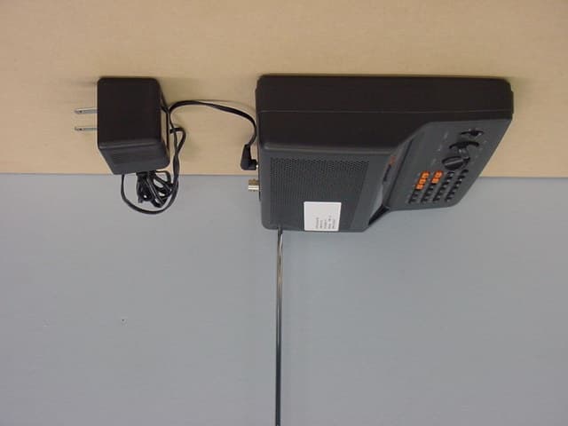
Click to zoom
Application Details
- Equipment Class
- CSR - Scanning Receiver
- Date of Grant
- May 29, 2002
- Application Purpose
- Original Equipment
- Date of Application
- May 29, 2002
- Equipment Note
- Scanning Receiver
- Frequency Range
- 380.00000000 - 512.00000000
- Company
- RadioShack Corporation
- Country
- United States
Documents & Files
Document Text
Text extracted from the exhibit documents filed with the FCC. Open a document above to read the original.
Users Manual
20-424 Owner’s Manual Page 1 RadioShack LOGO PRO-2018 200 Channel Desktop Scanner Owner’s Manual Please read before using this equipment The FCC Want You to Know This equipment has been tested and found to comply with the limits for a scanning receiver pursuant to Part 15 of the FCC Rules. These limits are designed to provide reasonable protection against harmful interference in a residential installation. This equipment generates, uses and can radiate radio frequency energy and, if not installed and used in accordance with the instructions, may cause harmful interference to radio communications. However, there is no guarantee that interference will not occur in a particular installation. If this equipment does cause harmful interference to radio or television reception, which can be determined by turning the equipment off and on, the user is encouraged to try to correct the interference by one or more of the following measures: • Reorient or relocate the receiving antenna. • Increase the separation between the equipment and receiver. • Connect the equipment into an outlet on a circuit different from that to which the receiver is connected. This device complies with Part 15 of the FCC Rules. Operation is subject to the following two conditions: 1. This device may not cause harmful interference, and 2. This device must accept any interference received, including interference that may cause undesired operation. Note: Mobile use of this scanner is unlawful or requires a permit in some areas. Check the laws in your area. 20-424 Owner’s Manual Page 2 WARNING: To reduce the risk of fire or shock hazard, do not expose this product to rain or moisture. © 2002 RadioShack Corporation. All Rights Reserved. RadioShack is a registered trademark used by Tandy Corporation. Hyperscan, Hypersearch, and Adaptaplug are trademarks used by Tandy Corporation. CONTENTS will add FEATURES Your RadioShack 200-Channel VHF/AIR/UHF Desktop Scanner lets you in on all the action! This scanner gives you direct access to over 25,000 frequencies, including those used by police and fire departments, ambulance services, government agencies, air, and amateur radio services. You can select up to 200 channels to scan, and you can change your selection at any time. The secret to your scanner’s ability to scan so many frequencies is its built-in microprocessor. Your scanner also has these special features: One Touch Search Banks – let you search preset frequencies in separate ham radio, police/fire/emergency, aircraft, weather, and marine banks, to make it easy to locate specific types of calls. Two-Second Scan Delay – delays scanning for 2 seconds before moving to another channel, so you can hear more replies. Ten Channel-Storage Banks – let you store up to 20 channels in each of 10 different banks, to group channels so you can more easily identify calls. Memory Backup – keeps the channel frequencies stored in memory for about 1 hour during a power loss. HyperSearch TM and HyperScan TM – let you set the scanner to search at up to 50 steps per 20-424 Owner’s Manual Page 3 second and to scan at up to 25 channel per second, to help quickly find interesting transmissions. Duplicate Frequency Check – automatically notifies you if you are about to store a frequency you have already stored, to help avoid wasting storage space. Tune – lets you search for new and unlisted frequencies starting from a specified frequency. Priority Channel – lets you program a frequency in the priority channel to be scanned every 2 seconds so you do not miss important calls. Weather Alert – automatically sounds the alarm tone to advise of hazardous weather conditions when the scanner detects an alert signal on the local NOAA weather channel. Lock-Out Function – lets you set your scanner to skip over specified channels or frequencies when scanning or searching. Liquid Crystal Display – makes it easy to view and change programming information at any time. Display Backlight – makes the scanner easy to read in low light situations. Supplied Telescoping Antenna – lets the scanner receive strong local signals. External Antenna Terminal – lets you connect an external antenna (not supplied) to the scanner. Your scanner can receive these bands: Frequency Range (MHz)Type of Transmissions 29-5410-Meter Ham Band, VHF Lo, 6-Meter Ham Band 108-136.9875Aircraft 137-174Military Land Mobile, 2-Meter Ham Band, VHF Hi 380-512 MHzUHF Aircraft, FGovernment, 70-cm Ham Band, UHF Standard Band, UHF “T” Band SCANNING LEGALLY Scanning is a fun and interesting hobby. You can hear police and fire departments, ambulance services, government agencies, private companies, amateur radio services, aircraft, and military operations. It is legal to listen to almost every transmission your scanner can receive. However, there are some electronic and wire communications that are illegal to intentionally intercept. These include: • telephone conversations (cellular, cordless, or other private means of telephone signal transmission) • pager transmissions • any scrambled or encrypted transmissions According to the Federal Electronic Communications Privacy Act (ECPA), and amended, you could 20-424 Owner’s Manual Page 4 be fined and possibly imprisoned for intentionally listening to, using, or disclosing the contents of such a transmission unless you have the consent of a party to the communication (unless such activity is otherwise illegal). These laws change from time to time and there might be state or local laws that also affect legal scanner usage. PREPARATION POWER SOURCES USING AC POWER You can power the scanner using the supplied 12V, 300mA AC adapter. Cautions: ! You must use a Class 2 power source that supplies 12V DC and delivers at least 300 mA. Its center tip must be set to positive and its plug must fit the scanner’s DC 12V jack. The supplied adapter meets these specifications. Using an adapter that does not meet these specifications could damage the scanner or the adapter. • Always c…
Text truncated - open the document above for the full version.
Attestation Statements
GENERAL RESEARCH OF ELECfRONICS, INC Phone. +813-5439-3611 SHISA NO.3 AMEREX SLOG. .3-12-17 MITA, MINATO-KU Fax: +813-5439-3644 TOKYO 108-0073, JAPAN April 3, 2002 Federal Commuf"!ications Commission Authorization and Evaluation Division Laboratory Division 7435 Oakland Mills Road Colombia, MD 21046 Ref.: Radio Shack Model 20-424, FCC ID: AAO2000424: This is to clarify that the above equipment is incapable of operating (tuning) or readily being altered by the user to operate, within the frequency bands to the Cellular Radiotelephone Service. The frequencies in question are deleted from the ROM during manufacture, and cannot be restored throl!gh any readily available process or component such as: installation of cuts, jumper wires, resisto~, diodes, or-plug-in IC's; deletion of such jtems; or reprogramming via access codes or external devices such as a personal computer. The receiver is incapable of converting digital cellular transmissions to analog voice audio. Assessing the vulnerability of the receiver to possible modification The receiver has the possibility of reducing the threshold value to discern transmissions from the Cellular Radiotelephone Service by making modification such as addJng jumper wire to the UHF RF tuning circuit and UHF mixer circuit. Design features that prevent modification of the receiver to receive Cellular Service The scanning receiver is designed to prevent any attempt for the user to modify the receiver to receive transmissions from the Cellular Radiotelephone Service by using epoxy to cover the r~uired parts of the UHF RF tuning circuit. Testing method used to determine compliance with the 38 dB rejection ratio The scanning receiver prevents transmi$sions more than 38 dB from the Cellular Radiotelephone Service from being received for the following reasons: 1. The image frequencies in the frequency range from 29 MHz to 54 MHz are shown as follows: GENERAL RESEARCH OF ELECTRONICS, INC. FR = 29 to 54 MHz. 108 to 136.9875 MHz IF = 10.7 MHz FR + 2 x IF = IMAGE FREQ. (29 to 54) + (2 x 10.7) = 50.4 to 75.4 MHz (108 to 136.9875) + (2 x 10.7) = 129.4 to 158.3875 MHz IMAGE FREQ. IMAGE FREQ. These image frequencies are not included within the Cellular Radiotelephone Service Frequency Band. 2. The image frequencies in the frequency range from 137 to 1 ir 4 MHz. 380 to 512 MHz are shown as follows: FR = 137 to 174 MHz, 380 to 512 MHz IF = 10.7 MHz FR -2 x IF = IMAGE FREQ. (137 to 174) -(2 x 10.7) = 115.6 to 152.6 MHz (380 to 512) -(2 x 10.7) = 358.6 to 490.6 MHz IMAGE FREQ. IMAGE FREQ. These image frequencies are not included within the Cellular Radiotel~phone Service Frequency Band. The 12 dB SINAD measurement method in the Cellular Radiotelephone Service used for frequencies that the receiver tunes and the signal rejection ratio gained by the measurement. SCOPE iSINAD !METER ~---~ 8 ohm LOAD Equipment Setup Block Diagram Measurement method Tune the receiver to the received frequency and output the receiving frequency from SG to obtain its 12 dB SINAD. Then output the interference frequency to obtain its 12 dB SINAD. The signal rejection ratio is the ratio between these two SSG output levels. GENERAL RESEARCH OF ELECTRONICS, INC. Test Results Frequency range (MHz) Received frequency (MHz) Cellular frequency range included (MHz) Interference frequency {MHz) Signal rejection ratio ldB) Equation for interference frequency reception (MHz) 417.850 to 429.350 825.000 to 848.000 825.000 837.300 848.000 71 70 69 60 59 58 69 70 71 56 56 57 {FR- IF) x 2 + IF = 825.000 {FR -IF) X 2 + IF = 837.300 (FR- IF) x 2 + IF = 848.000 428.550 to 440.050 825.000 to 848.000 428.550 434.000 440.050 {FR- IF) x 2 -IF = 825.000 {FR- IF) x 2- IF = 835.900 (~R- IF) x 2 -IF = 848.000 440.350 to 451.850 870.000 to 893.000 440.350 446.000 451.850 870.000 881.300 893.000 (FR-IF)x2 + IF = 870.000 (FR- IF) x 2 + IF = 881.300 (FR -IF) x 2 + IF = 893.000 451.050 to 462.550 870.000 to 893.000 870.000 879.900 893.000 (FR-IF) x 2 -IF = 870.000 (FR- IF) x 2- IF = 879.900 (FR- IF) x 2- IF = 893.000 FR = received frequency IF = 10.7 MHz The above test results indicate that all the signal rejection ratios for the Cellular Radiotelephone Servic~ Band are higher than 38 dB. Label Requirement The scanning receiver has a label affixed to the product shown on the attached drawing of the model label, which reads as follows: WARNING: MODIFICATION OF THIS DEVICE TO RECEIVE CELLULAR RADIOTELEPHONE SERVICE SIGNALS IS PROHIBITED UNDER FCC RULES AND FEDERAL LAW. Based on the above, we hereby attest that the equipment in question compiles fully with the provisions of 15.121 of FCC Rules. ~~. M. Ishizu a. Chi EnQineer 417.850 424.000 429.350 825.000 835.900 848.000 451.050 456.000 462.550
External Photos
Model: PRO-2018 FCCID: AAO2000315 EXTERNAL PHOTO Model: PRO-2018 FCCID: AAO2000315 EXTERNAL PHOTO Model: PRO-2018 FCCID: AAO2000315 EXTERNAL PHOTO Model: PRO-2018 FCCID: AAO2000315 EXTERNAL PHOTO Model: PRO-2018 FCCID: AAO2000315 EXTERNAL PHOTO
ID Label/Location Info
! FREQ. RANGE: 29-54. 108-13Ii.9875 137-174 380-512 MHz coNDmoNs: (1) THIS DEVICE MAY NOT CAUSE HARMFUL i. ., INTERFERENCE. AND (2) THIS DEVICE MUST ACCEPT ANY POWER.12V DC. 300mA ADAPTER NO. JOD-41U-02 INTERFERENCE RECEIVED INCLUDING INTERFERENCE FCC ID: AAO~!OOO424 THAT MAY CAUSE UNDESIRED OPERATION. WARNING:MOIDIFICATION OF THIS DEVICE TO RECEIVE C:USTOM MANUFACTURED IN CHINA CELLULAR RADIOTELEPHONE SERVICE SIGNALS IS j FOR RADIOSHACK ~RATION. FORT WORTH. TX 76102 PROHIBITED UNDER FCC RULES AND FEDERAL LAW. / 4-R2 REMARKS 1. MATERIAL: PLASTIC FOIL (0.1 mm) 2. FINISH: BLACK BASE/SILVER LETTERS ».? BY 2~o "'~ ..83.0111'11 REVISION IAPPROVEINUMBERI TITLE IQUANTI MATERIALI REMARK #0116 (PRO-2018) Cat. No.20-424 I ISSUED USA MODEL LABEL (MANUFACTURED IN CHINA) lfiEB21 '02 ~ SCALE ~TREAT I PAINT JAN. 25 2002 L4U ~ 2/1 DESIGN DRAWN DATE G.R.E. --rg 8/~
ID Label/Location Info
, ~ N ~ O O O N O ~ c - O O LL. '-' z O - J- « O O -J -J w m « ..J c - O O LL. -J w ID 5 -J w O O ~ [ ~~~ ~ ~ " , / O z ",,9 o o u. +"' c Q) E Q) +"' ~ M' '-' 10 '-' 0) - Lri 101 41 .c 1- " z z ~ ~ 0 ~ (I) o z o a: 1- 0 w -J w u. O :1: 0 a: « w (I) w cr: -J « a: w z w O
Test Report
APPLICATION FOR FCC CERTIFICATION For Radio Shack Corp. Scanning Receiver Model: 20-424 (PRO-2018) FCC ID: AAO2000424 Job # 3023503 Report # 30235031 Date of Testing: April 9 – 10 and May 13 - 15, 2002 Date of Report: May 17, 2002 Number of Pages: 26 This report shall not be reproduced except in full, without written approval of Intertek Testing Services. This report must not be used to claim product endorsement by NVLAP or any agency of the U.S. Government. The results contained in this report were derived from measurements performed on the identified test samples. Any implied performance of other samples on this report is dependent on the representative of the samples tested. NVLAP Laboratory Code: 200201-0 FCC Part 15 Scanning Rx Cert 1365 Adams Court, Menlo Park, CA 94025 Radio Shack Corp. , Model No: 20-424 (PRO-2018) FCC ID: AAO2000424 Date of Test: April 9 – 10 and May 13 - 15, 2002 Report #30235031 1 FCC Part 15 Certification Table of Contents AUTHORIZATION LETTER ...................................................................................................... 3 ATTESTATION LETTER TO FCC ∋ ∋∋ ∋ 15.121 .............................................................................. 4 TEST REPORT .............................................................................................................................. 5 0.0Summary of Test Results ................................................................................................... 5 1.0General Description .......................................................................................................... 6 1.1Product Description................................................................................................. 6 1.2Related Submittal(s) Grants..................................................................................... 6 1.3Test Methodology.................................................................................................... 6 1.4Test Facility............................................................................................................. 6 2.0System Test Configuration ................................................................................................ 7 2.1Justification.............................................................................................................. 7 2.2EUT Exercising Software ........................................................................................ 7 2.4Support Equipment List and Description ................................................................ 8 2.4.1 The FCC ID's for all equipment used in the tested system 2.4.2 Equipment Setup Block Diagram ................................................................ 8 2.5Equipment Modification.......................................................................................... 8 3.0Emission Results ................................................................................................................ 9 3.1Field Strength Calculation ..................................................................................... 10 3.2Radiated Emission Configuration Photograph ...................................................... 11 3.3Radiated Emission Data ........................................................................................ 12 3.4AC conducted Emission Configuration Photograph.............................................. 14 3.5Conducted Emission Data ..................................................................................... 15 Conducted Emission Data ................................................................................................. 16 4.0List of Test Equipment .................................................................................................... 18 5.0Antenna Requirement ..................................................................................................... 19 6.0Equipment Photographs ................................................................................................. 20 7.0Product Labeling ............................................................................................................. 21 7.1Label Artwork ....................................................................................................... 21 7.2Label Location ...................................................................................................... 22 8.0Technical Specifications .................................................................................................. 23 8.1Receiver Block Diagram....................................................................................... 23 8.2Receiver Circuit Diagram...................................................................................... 24 1365 Adams Court, Menlo Park, CA 94025 Radio Shack Corp. , Model No: 20-424 (PRO-2018) FCC ID: AAO2000424 Date of Test: April 9 – 10 and May 13 - 15, 2002 Report #30235031 2 FCC Part 15 Certification 9.0Instruction Manual .......................................................................................................... 25 10.0Document History ............................................................................................................ 26 1365 Adams Court, Menlo Park, CA 94025 Radio Shack Corp. , Model No: 20-424 (PRO-2018) FCC ID: AAO2000424 Date of Test: April 9 – 10 and May 13 - 15, 2002 Report #30235031 3 FCC Part 15 Certification AUTHORIZATION LETTER See attachment. 1365 Adams Court, Menlo Park, CA 94025 Radio Shack Corp. , Model No: 20-424 (PRO-2018) FCC ID: AAO2000424 Date of Test: April 9 – 10 and May 13 - 15, 2002 Report #30235031 4 FCC Part 15 Certification ATTESTATION LETTER TO FCC ∋ ∋∋ ∋ 15.121 See attachment. 1365 Adams Court, Menlo Park, CA 94025 Radio Shack Corp. , Model No: 20-424 (PRO-2018) FCC ID: AAO2000424 Date of Test: April 9 – 10 and May 13 - 15, 2002 Report #30235031 5 FCC Part 15 Certification TEST REPORT 0.0Summary of…
Text truncated - open the document above for the full version.
Test Setup Photos
Model: 20-424 (PRO-2018) FCCID: AAO2000424 TEST SE TUP PHOTO Model: 20-424 (PRO-2018) FCCID: AAO2000424 TEST SE TUP PHOTO Model: 20-424 (PRO-2018) FCCID: AAO2000424 TEST SE TUP PHOTO Model: 20-424 (PRO-2018) FCCID: AAO2000424 TEST SE TUP PHOTO Model: 20-424 (PRO-2018) FCCID: AAO2000424 TEST SE TUP PHOTO Model: 20-424 (PRO-2018) FCCID: AAO2000424 TEST SE TUP PHOTO
Contact Information
Applicant
Elizabeth Granados(Regulatory Affairs Manager)
Technical Contact
Intertek Testing ServicesDavid Chernomordik
[email protected]650 463 2900
1365 Adams Court · Menlo Park, California · United States
Non-Technical Contact
Intertek Testing ServicesStephenie Smith
[email protected]650 463 2900
Test Firm
Intertek Testing Services NA Inc.John Quigley
Technical Specifications
| # | Rule Parts | Frequency Range | Power Output |
|---|---|---|---|
| 4 | 15B | 380 MHz - 512 MHz | - |
Other Applications from RadioShack Corporation

AAO2302500
Feb 10, 2015Bluetooth Power Bank
Equipment Class
DXX - Part 15 Low Power Communication Device Transmitter
AAO4300124C
May 02, 2013900MHz Wireless Intercom
Equipment Class
DXT - Part 15 Low Power Transceiver, Rx Verified
AAO1200876
Nov 30, 2011Universal FM Transmitter
Equipment Class
DXX - Part 15 Low Power Communication Device Transmitter
AAO1200962
Aug 02, 2011Universal FM Transmitter
Equipment Class
DXX - Part 15 Low Power Communication Device Transmitter
AAO1500044T
Apr 02, 20112.4GHz Digital Wireless Rear Speaker Kit - Transmitter
Equipment Class
DSS - Part 15 Spread Spectrum Transmitter