AAO2000466Scanning Receiver
RadioShack Corporation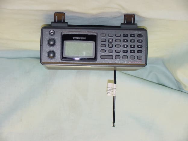
Click to zoom
Application Details
- Equipment Class
- CSR - Scanning Receiver
- Date of Grant
- Jun 13, 2001
- Application Purpose
- Original Equipment
- Date of Application
- Jun 13, 2001
- Equipment Note
- Scanning Receiver
- Frequency Range
- 894.00000000 - 960.00000000
- Company
- RadioShack Corporation
- Country
- United States
Documents & Files
Document Text
Text extracted from the exhibit documents filed with the FCC. Open a document above to read the original.
Users Manual
20-466 Owner’s Manual Page 1 RadioShack LOGO www.radioshack.com SM PRO-2053 Base Scanner Owner’s Manual Please read before using this equipment. Contents Will add © 2001 RadioShack Corporation. All Rights Reserved. RadioShack, RadioShack.com, and Adaptaplug are registered trademarks used by Tandy Corporation. Hypersearch and Hyperscan are trademarks used by Tandy Corporation. Motorola, Smartnet and Privacy Plus are registered trademarks of Motorola Inc. EDACS is a registered trademark of GE/Ericsson Inc. Features Your RadioShack Base Scanner is one of a new generation of scanners designed to track Motorola® Type I and II (such as Smartnet® and Privacy Plus®) and hybrid analog trunking systems, and GE/Ericsson (EDACS®) type systems, which are extensively used in many communication systems. Trunking communications systems let a large group of 2-way radio users (or even different groups of 2- way radio users) efficiently use a set of frequencies. Instead of selecting a specific frequency for a transmission, the user simply selects a talk group. The trunking system automatically transmits the call on the first available frequency, and also sends a code that uniquely identifies that transmission. Since the trunking system might send a call and its response on different frequencies, it is difficult to listen to trunked communications using a regular scanner. The scanner monitors the data sent with a 2-way radio transmission, so you can hear the call and response for that user and more easily “follow” the conversation. The scanner also lets you scan conventional transmissions, and is preprogrammed with service search banks for convenience. By pressing a single button, you can quickly search those frequencies most commonly used by public service and other agencies without tedious and complicated programming. This scanner gives you direct access to over 59,000 frequencies including those used by police and fire departments, ambulance services, government agencies, air, and amateur radio services. Your scanner includes these features: 20-466 Owner’s Manual Page 2 Simultaneous Trunking Operation – tracks two trunking systems (Motorola and EDACS) and conventional systems at the same time. 10 Channel-Storage Banks – let you store 30 channels in each bank (300 channels) to group channels so calls are easier to identify. 10 ID-Storage banks – let you store 1,000 IDs in 10 ID banks, 5 sub-ID banks, 20 IDs are programmed in each 5 sub-ID banks and let you easy identify the ID code. 12-Character, 4-Line, Dot-Matrix Display – shows you detailed operating information and lets you easily program the scanner. Weather Alert – automatically sounds the alarm tone to advise of hazardous weather conditions when it detects the alert signal on the local National Oceanic and Atmospheric Administration (NOAA) weather channel during priority operation. Digital Weather Alert – displays the weather event text with three alert levels so you can see and hear the reason for the alert. Preprogrammed Frequency Ranges – lets you search for transmissions within preset frequency ranges or within ranges you set, to reduce search time and select interesting frequencies more quickly. Data Cloning – lets you transfer the programmed data to another PRO-2053 or PRO-93 scanner. You can also upload or download the programmed data to or from a PC using an optional interface kit. Triple Conversion Superheterodyne Receiver – virtually eliminates any interference from intermediate frequency (IF) images, so you hear only the frequency you select. Hyperscan TM and Hypersearch TM – the scanner scans and searches at up to 60 steps per second, to help you quickly find interesting transmissions. Scan Delay – delays scanning for about 2 seconds before moving to another channel in conventional mode, so you can hear more replies that are made on the same channel. Priority Channel – you can set the scanner to check one channel every 2 seconds so you do not miss important calls. Signal Attenuation (Attenuate) – lets you program in your scanner to reduce the scanner’s sensitivity to strong local signals, to reduce interference or noise caused by these signals. Text Input – lets you input a text label for each channel, talk group ID, bank, or other memory location so you can easily know about the transmission you are hearing. Lock Out Function – lets you set your scanner to skip over specified channels or frequencies when scanning or searching, and skip over IDs when tracking trunked systems. 20-466 Owner’s Manual Page 3 Key Lock – lets you lock the scanner’s keys to help prevent accidentally changing the scanner’s programming. Telescoping Antenna – lets the scanner receive strong local signals. External BNC Antenna Connector – lets you connect an external antenna (not supplied) to the scanner. Memory Backup – keeps the frequencies stored in memory for an extended time even without internal batteries. Supplied Police Call Trunking Guide – provides a quick reference to public safety trunking radio systems in the United States. WARNING: To reduce the risk of fire or shock hazard, do not expose this product to rain or moisture. Your scanner can receive these frequencies: . 25—54 MHz . 108—136.9875 MHz . 137—174 MHz . 216—225 MHz . 406—512 MHz . 806—823.9875 MHz . 849—868.9875 MHz . 894—960 MHz . 1240—1300 MHz This Owner’s Manual also includes the section “A General Guide to Scanning” on Page XX to help you target frequency ranges in your service area so you can search for a wide variety of transmissions. FCC NOTICE Your scanner might cause TV or radio interference even when it is operating properly. To determine whether your scanner is causing the interference, turn off your scanner. If the interference goes away, your scanner is causing the interference. Try the following methods to eliminate the interference. . Move your scanner away from the TV or radio. . Connect your scanner to an outlet that is on a different electrical circuit from the TV or radio. …
Text truncated - open the document above for the full version.
Attestation Statements
Phone: +813-5439-3611 Fax: +813-5439-3644 SHIBA NO.3 AMEREX BLDG. 12-17 MITA 3-CHOME, MINATO-KU TOKYO 108-0073, JAPAN Apr. 2, 2001 Federal Communications Commission Authorization and Evaluation Division Laboratory Division 7435 Oakland Mills Road Colombia, MD 21046 Ref.: Radio shack Model 20-466, FCC ID: AAO2000466 This is to clarify that the above equipment is incapable of operating (tuning) or readily being altered by the user to operate, within the frequency bands to the Cellular Radiotelephone Service. The frequencies in question are deleted from the ROM during manufacture, and cannot be restored through any readily available process or component such as: installation of cuts, jumper wires, resistors, diodes, or plug-in IC’s; deletion of such items; or reprogramming via access codes or external devices such as a personal computer. The receiver is incapable of converting digital cellular transmissions to analog voice audio. Assessing the vulnerability of the receiver to possible modification The receive has the possibility of reducing the threshold value to discern transmissions from the Cellular Radiotelephone Service by making modification such as adding jumper wire to the RF band pass filters. Design features that prevent modification of the receiver to receive Cellular Service The scanning receiver is designed to prevent any attempt for the user to modify the receiver to receive transmissions from the Cellular Radiotelephone Service by using epoxy to cover the required parts of the RF circuitry including control circuits and band pass filters. Testing method used to determine compliance with the 38 dB rejection ratio Testing method The 12 dB SINAD measurement method in the Cellular Radiotelephone Service used for frequencies that the receiver tunes and the signal rejection ratio gained by the measurement. GENERAL RESEARCH OF ELECTRONICS, INC. Equipment Setup Block Diagram Measurement method Tune the receiver to the received frequency and outputs the receiving frequency from SG to obtain its 12 dB SINAD. Then output the interference frequency to obtain its 12 dB SINAD. The signal rejection ratio is the ratio between these two SSG output levels. The scanning receiver prevents transmissions more than 38 dB from the Cellular Radiotelephone Service from being received for the following reasons: 1. The image frequencies in the frequency range from 25 MHz to 512 MHz are shown as follows: FR = 25 to 54 MHz, 108 to 174 MHz, 216.0025 to 225 MHz, 406 to 512 MHz IMAGE FREQ. = FR + 1 st IF x 2 1 st IF = 1 st Local – FR 1 st Local = A x 0.075 A = (FR + 380.8)/0.075 = A.xxx (Cut away decimal) (25 to 54) + (1 st IF x 2) = 786.5 to 815.55 MHz IMAGE FREQ. (132.4125 to 174) + (1 st IF x 2) = 893.8875 to 935.55 MHz IMAGE FREQ. (216.0025 to 225) + (1 st IF x 2) = 977.5475 to 986.55 MHz IMAGE FREQ. (406 to 512) + (1 st IF x 2) = 1167.5 to 1273.6 MHz IMAGE FREQ. SSG EUT 8 ohm load SCOPE SINAD meter These image frequencies are not included within the Cellular Radiotelephone Service Frequency Band except as follows. (108 to 132.4875) + (1 st IF x 2) = 869.550 to 893.9625 MHz IMAGE FREQ. Test Results 108 to 132.4875 MHz Frequency range (MHz) Cellular frequency range included (MHz) Received frequency (MHz) Interference frequency (MHz) Signal rejection ratio (MHz) Equation for interference frequency reception (MHz) 108.000 to 132.4875 869.550 to 893.9625 108.000 124.000 132.4875 869.550 885.500 893.9625 50 47 46 FR + (IF x 2) = 869.550 FR + (IF x 2) = 885.500 FR + (IF x 2) = 893.9625 The above test results indicate that all the signal rejection ratios for the Cellular Radiotelephone Frequency Service Band are higher than 38 dB. 2. The image frequencies in the frequency range from 806 to 1300 MHz are shown as follows: FR = 806 to 823.9875 MHz, 849 to 868.9875 MHz, 894 to 960 MHz, 1240 to 1300 MHz IMAGE FREQ. = FR – 1 st IF x 2 1 st IF = FR – 1 st Local 1 st Local = A x 0.075 A = (FR – 380.8)/0.075 = A.xxx (Cut away decimal) (806 to 823.9875) – (1 st IF x 2) = 44.35 to 62.3625 MHz IMAGE FREQ. (849 to 868.9875) – (1 st IF x 2) = 87.3 to 107.3625 MHz IMAGE FREQ. (894 to 960) – (1 st IF x 2) = 132.3 to 198.3 MHz IMAGE FREQ. (1240 to 1300) – (1 st IF x 2) = 478.4 to 538.4 MHz IMAGE FREQ. These image frequencies are not included within the Cellular Radiotelephone Service Frequency Band. 3. Other rejection results Test Results (1) Frequency range (MHz) Cellular frequency range included (MHz) Received frequency (MHz) Interference frequency (MHz) Signal rejection ratio (dB) Equation for interference frequency reception (MHz) 25.000 to 29.145 35.825 to 44.145 836.500 to 848.895 869.075 to 893.895 25.000 to 29.145 35.825 40.000 44.145 836.500 to 848.895 869.075 881.500 893.895 74 70 65 64 64 1 st Lo x 3 – 1 st IF = 836.500 to 1 st Lo x 3 – 1 st IF = 848.895 1 st Lo x 3 – 1 st IF = 869.075 1 st Lo x 3 – 1 st IF = 881.500 1 st Lo x 3 – 1 st IF = 893.895 221.6025 to 225.000 824.0025 to 830.775 221.6025 to 225.000 824.0025 to 830.775 69 68 1 st Lo x 2 – 1 st IF = 824.000 to 1 st Lo x 2 – 1 st IF = 830.775 1 st IF = 1 st Local – FR 1 st Local = A x 0.075 A= (FR + 380.8)/0.075 = A.xxx (Cut away decimal) Test Results (2) Frequency range (MHz) Cellular frequency range included (MHz) Received frequency (MHz) Interference frequency (MHz) Signal rejection ratio (dB) Equation for interference frequency reception (MHz) 849.000 to 859.6875 838.300 to 848.9875 849.000 to 859.6875 838.300 to 848.9875 80 80 {(FR x 2) – 2 nd IF}/2 = 838.300 to {(FR x 2) – 2 nd IF}/2 = 838.9875 866.800 to 868.9875 824.000 to 826.1875 866.800 to 868.9875 824.000 to 826.1875 51 51 FR + (2 nd IF x 2) = 824.000 to FR + (2 nd IF x 2) = 826.1875 894.000 to 904.6875 883.300 to 893.9875 894.000 to 904.6875 883.300 to 893.9875 81 81 {(FR x 2) – 2 nd IF}/2 = 883.300 to {(FR x 2) – 2 nd IF}/2 = 893.9875 911.800 to 936.7875 869.000 to 893.9875 911.800 920.000 936.7875 869.000 877.200 893.9875 51 51 51 FR + (2 nd IF x 2) = 869.000 FR + (2 nd IF x 2) = 877.200 FR + (2 …
Text truncated - open the document above for the full version.
External Photos
1365 Adams Court, Menlo Park, CA 94025 Radio Shack, A Division of Tandy Corporation, Model No: 20-466 (PRO-2053) FCC ID: AAO2000466Date of Test: April 25, 2001 Report #20462052FCC Part 15 Certification 20 EUT Photo 1365 Adams Court, Menlo Park, CA 94025 Radio Shack, A Division of Tandy Corporation, Model No: 20-466 (PRO-2053) FCC ID: AAO2000466Date of Test: April 25, 2001 Report #20462052FCC Part 15 Certification 21 EUT Photo 1365 Adams Court, Menlo Park, CA 94025 Radio Shack, A Division of Tandy Corporation, Model No: 20-466 (PRO-2053) FCC ID: AAO2000466Date of Test: April 25, 2001 Report #20462052FCC Part 15 Certification 22 EUT Photo 1365 Adams Court, Menlo Park, CA 94025 Radio Shack, A Division of Tandy Corporation, Model No: 20-466 (PRO-2053) FCC ID: AAO2000466Date of Test: April 25, 2001 Report #20462052FCC Part 15 Certification 23 EUT Photo
Test Report
APPLICATION FOR FCC CERTIFICATION For Radio Shack, A Division of Tandy Corporation Scanning Receiver Model: 20-466 (PRO-2053) FCC ID: AAO2000466 Job # J20046205 Report #20462052 Date of Testing: April 25, 2001 Date of Report: April 26, 2001 Number of Pages: 34 + Data Pages This report shall not be reproduced except in full, without written approval of Intertek Testing Services. This report must not be used to claim product endorsement by NVLAP or any agency of the U.S. Government. The results contained in this report were derived from measurements performed on the identified test samples. Any implied performance of other samples on this report is dependent on the representative of the samples tested. NVLAP Laboratory Code: 200201-0 FCC Part 15 Scanning Rx Cert, Ver 3/97 k:\..\FCC\scanrx.cer 1365 Adams Court, Menlo Park, CA 94025 Radio Shack, A Division of Tandy Corporation, Model No: 20-466 (PRO-2053) FCC ID: AAO2000466Date of Test: April 25, 2001 Report #20462052FCC Part 15 Certification 1 Table of Contents AUTHORIZATION LETTER.................................................................................................3 ATTESTATION LETTER TO FCC ∋∋15.121..........................................................................4 TEST REPORT.........................................................................................................................5 0.0Summary of Test Results...............................................................................................5 1.0General Description.......................................................................................................6 1.1Product Description.............................................................................................6 1.2Related Submittal(s) Grants..................................................................................6 1.3Test Methodology................................................................................................6 1.4Test Facility.........................................................................................................6 2.0System Test Configuration............................................................................................7 2.1Justification..........................................................................................................7 2.2EUT Exercising Software.....................................................................................7 2.3Support Equipment List and Description..............................................................8 2.3.1The FCC ID's for all equipment used in the tested system (included inserted cards, which have grants) are:...................................................................8 2.3.2Equipment Setup Block Diagram..............................................................8 2.4Equipment Modification.......................................................................................9 3.0Emission Results..........................................................................................................10 3.1Field Strength Calculation..................................................................................11 3.2Radiated Emission Configuration Photograph.....................................................12 3.3Radiated Emission Data.....................................................................................14 3.4AC conducted Emission Configuration Photograph............................................15 3.5Conducted Emission Data..................................................................................17 4.0Antenna Requirement.................................................................................................18 5.0Equipment Photographs.............................................................................................19 6.0Product Labeling.........................................................................................................29 6.1Label Artwork....................................................................................................29 6.2Label Location...................................................................................................30 7.0Technical Specifications..............................................................................................31 7.1Receiver Block Diagram.....................................................................................31 7.2Receiver Circuit Diagram...................................................................................32 8.0Instruction Manual......................................................................................................33 1365 Adams Court, Menlo Park, CA 94025 Radio Shack, A Division of Tandy Corporation, Model No: 20-466 (PRO-2053) FCC ID: AAO2000466Date of Test: April 25, 2001 Report #20462052FCC Part 15 Certification 2 9.0Document History........................................................................................................34 1365 Adams Court, Menlo Park, CA 94025 Radio Shack, A Division of Tandy Corporation, Model No: 20-466 (PRO-2053) FCC ID: AAO2000466Date of Test: April 25, 2001 Report #20462052FCC Part 15 Certification 3 AUTHORIZATION LETTER Please see attached page. 1365 Adams Court, Menlo Park, CA 94025 Radio Shack, A Division of Tandy Corporation, Model No: 20-466 (PRO-2053) FCC ID: AAO2000466Date of Test: April 25, 2001 Report #20462052FCC Part 15 Certification 4 ATTESTATION LETTER TO FCC ∋∋15.121 Please see attached page. 1365 Adams Court, Menlo Park, CA 94025 Radio Shack, A Division of Tandy Corporation, Model No: 20-466 (PRO-2053) FCC ID: AAO2000466Date of Test: April 25, 2001 Report #20462052FCC Part 15 Certification 6 1.0General Description 1.1Product Description The General Research of Electronics, Inc. Model No.: 20-514 (PRO-89) is a scanning receiver used to listen to police and fire departments, ambulance services, government agencies, private compan…
Text truncated - open the document above for the full version.
Test Setup Photos
1365 Adams Court, Menlo Park, CA 94025 Radio Shack, A Division of Tandy Corporation, Model No: 20-466 (PRO-2053) FCC ID: AAO2000466Date of Test: April 25, 2001 Report #20462052FCC Part 15 Certification 12 3.2Radiated Emission Configuration Photograph Radiated Emission Test Setup 1365 Adams Court, Menlo Park, CA 94025 Radio Shack, A Division of Tandy Corporation, Model No: 20-466 (PRO-2053) FCC ID: AAO2000466Date of Test: April 25, 2001 Report #20462052FCC Part 15 Certification 13 3.2Radiated Emission Configuration Photograph (Continued) Radiated Emission Test Setup 1365 Adams Court, Menlo Park, CA 94025 Radio Shack, A Division of Tandy Corporation, Model No: 20-466 (PRO-2053) FCC ID: AAO2000466Date of Test: April 25, 2001 Report #20462052FCC Part 15 Certification 15 3.4AC conducted Emission Configuration Photograph Conducted Emission Test Setup 1365 Adams Court, Menlo Park, CA 94025 Radio Shack, A Division of Tandy Corporation, Model No: 20-466 (PRO-2053) FCC ID: AAO2000466Date of Test: April 25, 2001 Report #20462052FCC Part 15 Certification 16 3.4AC conducted Emission Configuration Photograph (Continued) Conducted Emission Test Setup
Contact Information
Applicant
Elizabeth Granados(Regulatory Affairs Manager)
Technical Contact
Intertek Testing Services NA Inc.David Chernomordik
[email protected](650) 463-2900
1365 Adams Court · Menlo Park, California · United States
Non-Technical Contact
Intertek Testing Services NA Inc.Courtney Sherbourne
[email protected](650) 463-2900
Test Firm
Intertek Testing Services NA Inc.John Quigley
Technical Specifications
| # | Rule Parts | Frequency Range | Power Output |
|---|---|---|---|
| 8 | 15B | 894 MHz - 960 MHz | - |
Other Applications from RadioShack Corporation

AAO2302500
Feb 10, 2015Bluetooth Power Bank
Equipment Class
DXX - Part 15 Low Power Communication Device Transmitter
AAO4300124C
May 02, 2013900MHz Wireless Intercom
Equipment Class
DXT - Part 15 Low Power Transceiver, Rx Verified
AAO1200876
Nov 30, 2011Universal FM Transmitter
Equipment Class
DXX - Part 15 Low Power Communication Device Transmitter
AAO1200962
Aug 02, 2011Universal FM Transmitter
Equipment Class
DXX - Part 15 Low Power Communication Device Transmitter
AAO1500044T
Apr 02, 20112.4GHz Digital Wireless Rear Speaker Kit - Transmitter
Equipment Class
DSS - Part 15 Spread Spectrum Transmitter