AAO210170640-Channel Citizen Band Transceiver
RadioShack Corporation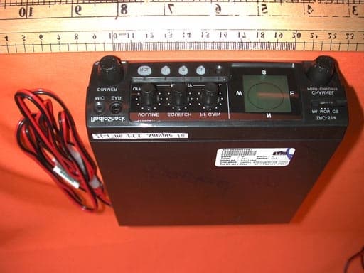
Click to zoom
Application Details
- Equipment Class
- TNB - Licensed Non-Broadcast Station Transmitter
- Date of Grant
- Mar 13, 2002
- Application Purpose
- Original Equipment
- Date of Application
- Jan 15, 2002
- Equipment Note
- 40-Channel Citizen Band Transceiver
- Frequency Range
- 26.96500000 - 27.40500000
- Company
- RadioShack Corporation
- Country
- United States
Documents & Files
Document Text
Text extracted from the exhibit documents filed with the FCC. Open a document above to read the original.
Users Manual
Owner’s ManualPlease read before using this equipment. 40 Channel Mobile CB with Digital Compass, and EL Backlit LCD Display 21-1706.fm Page 1 Wednesday, January 9, 2002 8:37 AM 2 Features à Features Your RadioShack 40 Channel Mobile CB is a great way to communicate with other CB radio operators. You can mount it in a vehicle for mobile use, or in your home for use as a base station. Your CB has these advanced features: LCD display with EL backlight on display and controls — lets you see the CB’s operating status at a glance and helps you easily see the display and controls when you use the CB at night. Digital Compass — aids navigation on the road. Emergency Channel One Touch Access — lets you quickly switch to Channel 9 or 19 so you can monitor or report emergency situations. 3 Channel Memories — let you easily access your favorite channels. Last Channel Recall (RCL) — Lets you quickly recall the last channel used. Dual Channel Controls — let you tune the channel from the transceiver or the microphone. RF Gain Control — lets you adjust the receiver’s gain to match the strength of the signal. Phase-Locked Loop (PLL) Frequency Synthesizer — provides highly accurate and stable tuning. Two Built-In Ceramic Filters — ensure superior channel selectivity and freedom from adjacent channel interference. Automatic Modulation Control — prevents the transmitter signal from over-modulating and distorting. Automatic Noise Limiter — reduces impulse-type noises while receiving. Built-In PA (Public Address) Amplifier — lets you use your CB as a public address system when you add an optional PA speaker. Universal Mounting Bracket — lets you mount your CB securely in your vehicle. Note: To use this CB, you must connect a mobile or base station antenna. Your local RadioShack store has a wide variety of antennas. For more information, see “Connecting an Antenna” on Page 4. FCC INFORMATION The Federal Communications Commission (FCC) does not require you to have a license to operate this CB radio. However, you must know Part 95 of FCC Rules. It explains the proper operation of a Class D citizen’s band transceiver. We enclosed a copy of Part 95 with your CB radio. Warning: Do not open the CB radio to make any internal adjustments. A CB radio is set up to transmit a regulated signal on an assigned frequency. It is against the law to alter or adjust the settings inside the unit to exceed these limitations. To be safe and sure: • Never open your CB radio’s case. • Never change or replace anything in your CB radio. © 2002 RadioShack Corporation. All Rights Reserved. RadioShack and RadioShack.com are trademarks used by RadioShack Corporation. 21-1706.fm Page 2 Wednesday, January 9, 2002 8:37 AM 3 Installation Your CB radio might cause TV or radio interference even when it is operating properly. To determine whether your CB is causing the interference, turn off your CB. If the interference goes away, your CB is causing it. Try to eliminate the interference by: • moving your CB away from the receiver • contacting your local RadioShack store for help This device complies with Part 15 of the following two conditions: (1) this device may not cause harmful interference, and (2) this device must accept any interference received, including interference that may cause undesired operation. à Installation ATTACHING THE MICROPHONE HOLDER You can attach the microphone holder to the right side of the transceiver or to another location in your vehicle. To attach the holder to the transceiver, secure the holder to the right side using the supplied 3 mm screws and lock washer. To attach the holder to another location in the vehicle, such as the dashboard, follow these steps. 1. Using the holder as a template, mark the positions for the mounting screw holes at the desired location. 2. At each marked position, drill a small starter hole. Caution: Be careful not to drill into anything behind the mounting surface. 3. Attach the holder at the mounting location using the supplied machine screws, spring washers, plain washers, and nuts. Note: If you cannot reach behind the mounting surface to attach the nuts on the machine screws, use the supplied 3 mm plain washers and self-tapping screws. MOUNTING THE TRANSCEIVER The most common mounting location for this CB is under a vehicle’s dashboard. However, if you plan to use the CB as a base station, you can place it on a desk, shelf, or table (see “Using the Transceiver as a Base Station” on Page 6). If you are mounting the CB in a vehicle, choose a location where: • You can easily reach the CB. • Wires and cables are clear of the vehicle’s pedals or other moving parts. 21-1706.fm Page 3 Wednesday, January 9, 2002 8:37 AM 4 Installation • The CB is not directly in front of heating vents. • All wires and cables can reach their connection points. Warnings: • If you use the CB in a vehicle, mount it securely to avoid damage to the CB or vehicle or injury to anyone in the vehicle during sudden starts or stops. • Do not mount the CB where it could damage or interfere with the operation of any passive restraint safety device (an airbag or seat belt). Follow these steps to mount the CB using the supplied hardware. 1. Using the mounting bracket as a template, mark the positions for the screw holes on the mounting surface. 2. In each marked location, drill a small starter hole. Caution: Be careful not to drill into objects behind the mounting surface. 3. Mount the bracket to the mounting surface with the supplied 5 mm bolts, spring washers, plain washers, and nuts. Note: If you cannot reach behind the mounting surface to attach the nuts on the bolts, use the supplied 5 mm self- tapping screws and plain washers to secure the bracket. 4. Peel the backings off the adhesive on the back of the supplied rubber washers and attach the washers to the mounting holes on the CB. then attach the CB to the mounting bracket using the mounting knobs. CONNECTING AN ANTENNA There are many different types of CB antennas…
Text truncated - open the document above for the full version.
External Photos
Test SetupFCCID : AAO2101706 External Photo -front External Photo - rear
Internal Photos
Test SetupFCCID : AAO2101706 Internal Photo - 1 Internal Photo - 2 Test SetupFCCID : AAO2101706 Internal Photo - 3 Internal Photo – 4 Test SetupFCCID : AAO2101706 Internal Photo - 5 Internal Photo – 6 Test SetupFCCID : AAO2101706 Internal Photo - 7
Parts List/Tune Up Info
TX VCO VOLTAGE ALIGNMENT PROCEDURE 1. TX ALIGNMENT ( THE CONNECTION IS AS ABOVE) 1. SET THE UNIT TO CHANNEL 19 WITH TX MODE, ADJUST T502 TO GET THE 2.5+/-0.2V DC DISPLAY ON THE VOLTAGE METER. 2. ADJUST T4,T5,T6, AND L8 IN SEQUENCE TO GET THE MAX POWER RECORDS ON THE POWER METER, THE POWER SHOULD BE WITHIN 3.2 to 3.7W. 3. ADJUST C551 UNTIL THE TRANSMIT FREQUENCY IS 27.185MHz +/-300Hz. RX VCO 2. Rx ALIGNMENG ( THE CONNECTION IS AS ABOVE) 1. SET THE UNIT TO CHANNEL 19 WITH RX MODEL. 2. ADJUST T501 TO GET 2.5+/- 0.2V DC WHICH IS RECORDED ON THE VOLTAGE METER. 3. SET THE RF GENERATOR TO 27.185MHz WITH 1KHz 30% AM MODULATION. 8 OHM RESISTIVE LOADING DISTORTION METER RF SIGNAL GENERATOR DC POWER 13.8V/3A UUT 21-1706 DIGITAL VOLTAGE METER SPECTRUM ANALYZER 8920 FREQUENCY COUNTER DC POWER 13.8V/3A UUT 21-706 DIGITAL VOLTAGE METER POWER METER 20dB ATT LOADINGLPF 4. ADJUST SQ TO MINIMUM POSITION AND THERF GAIN TO MAXIMUM POSITON POSITION. 5. ADJUST THE AUDIO VR TO MAKE THE AUDIO OUTPUT TO BE A REFERENCE OUTPUT. 6. ADJUST Q5 TO GET THE MANIMUM AUDIO DISTORTION. 7. REDUCE THE OUTPUT RF POWER TO BE 1uV. 8. ADUST L1,T1,T2,T3 TO GET THE MAXIMUM AUDIO OUTPUT. 9. CHECK THE MAXIMUM SENSITIVITY TO BE BELOW 0.6uV AND 10dB S/N SENSITIVITY IS BELOW 1uV. COMPASS ALIGNMENT 1. THE CONNECTION IS AS ABOVE. 2. KEEP THE COMNPASS PCB TO BE ON A LEVEL GROUND AND ROTATE THE PCB TO GET THE OUTPUT DATA TO BE MOST A LINE. 3. ADJUST VR 603 OR VR604 TO GET THE DATA LINE TO BE AROUND 2V AND THE VP-P OF THE DATA SHOULD BE WITHIN 1-3V. 4. REPEAT THE STEP 2 AND 3 TO GET THE ANOTHER DATA. NOTE: DON'T PLACE ANY MAGNETIC COMPONENTS NEAR THE CONPASS BOARD DURING THE COMPASS ALIGNMENT IS IN PROCESSING. COMPASS BOARD STORAGE SCOPE DC POWER 13.8V/3A UUT 21-1706
RF Exposure Info
INTERTEK TESTING SERVICES FCC ID: AAO2101706 EXHIBIT 15 RF EXPOSURE INTERTEK TESTING SERVICES FCC ID: AAO2101706 15.0 RF Exposure The manufacturer does not specify or sale any antenna with the radio identified in this report. The manufacturer applies for the General Population/Uncontrolled Environment. The maximum distance, from the antenna at which MPE is met or exceeded, is calculated from the equation relating field strength E in V/m, transmit power P in Watts, transmit antenna numeric gain G, and separation distance in meters: EVm PG d (/)= ××30 Power density: PmWcm E d (/) 2 2 3770 = The limit for general population/uncontrolled exposure applicable to Bystanders (at 27.405 MHz) = 180/(f(MHz)) 2 in mW/ cm 2 MPE CALCULATION 1. Antenna: Typical CB antenna available on the market and commonly chosen by end-users for vehicle application. Antenna gain is -4.5 dBi as compared to an ideal ½-wave dipole (0 dBd = 2.15 dBi) 2. Frequency: 27.405 MHz. Limit for General Population/Uncontrolled Environment (Bystanders): 0.24 mW/ cm 2 3. Separation distance: Conducted Power delivered to antenna Largest (worst-case) Separation Distance (Watt)(cm) 3.727 1.85 (50%)19 Note - Source-base time-averaging duty factor = 50% Instructions will be placed in the user manual instructing installers and users to maintain the MPE distances during operation of the EUT.
Test Report
Modulation Frequency Response 0.0 5.0 10.0 15.0 20.0 25.0 100100010000 Modulation Frequency (Hz) Modulation Input relative to 0dB (dB)
Test Report
Modulation Limiting Characteristic 0 20 40 60 80 100 -80-70-60-50-40-30-20 Modulation Input (dBm) Modulation (%) at 500Hz at 1000Hz at 2500Hz at 3125Hz
Test Report
• The test results rep orted in this rep ort shall refer only to the samp el actually tested and shall not refer or be deemed a refer to bulk from which such a samp le may be said to have been obtained . • This rep ort shall not be rep roduced excep t in full without p rior authorization from Intertek Testing Services Hong Kong Limit ed. FCC ID: AAO2101706 RadioShack Corporation Application For Certification (FCC ID: AAO2101706) January 15, 2002 WO# 0113899 WL/at January 15, 2002 INTERTEK TESTING SERVICES FCC ID: AAO2101706 i SUMMARY OF CONTENTS LIST OF EXHIBITS INTRODUCTION EXHIBIT 1 :General Description EXHIBIT 2 :System Test Configuration EXHIBIT 3 :RF Power Output EXHIBIT 4 :Modulation Characteristics EXHIBIT 5 :Occupied Bandwidth EXHIBIT 6 :Spurious Emission EXHIBIT 7 :Frequency Stability EXHIBIT 8 :Technical Specifications EXHIBIT 9 :Product Labelling EXHIBIT 10 :Photographs EXHIBIT 11: Instruction Manual EXHBIIT 12: CB Transmitter Power EXHIBIT 13: Tune Up Procedure EXHIBIT 14: Part List INTERTEK TESTING SERVICES FCC ID: AAO2101706 ii MEASUREMENT/TECHNICAL REPORT Application:RadioShack Corporation Model No.:RadioShack 21-1706 Date:January 15, 2002 This report concerns (check one:)Original Grant X Class II Change Equipment Type: CB Radio Station (example: computer, printer, modem. etc.) Deferred grant requested per 47 CFR 0.457(d)(1)(ii)? Yes No X If yes, defer until: date Company Name agrees to notify the Commission by: date of the intended date of announcement of the product so that the grant can be issued on that date. Report prepared by:Tommy Leung Intertek Testing Services. 2/F., Garment Centre, 576 Castle Peak Road, Kowloon, Hong Kong. Phone: 852-2173-8538 Fax:852-2741-1693 INTERTEK TESTING SERVICES FCC ID: AAO2101706 iii Table of Contents 1.1 Product Description ........................................................................................................................................2 2.0 System Test Configuration ...............................................................................................................................5 2.1 Justification.....................................................................................................................................................5 2.2 EUT Exercising Software................................................................................................................................6 4.0 Frequency Deviation .......................................................................................................................................13 6.0 Equipme nt Photographs ..................................................................................................................................23 7.0 Product Labe lling ............................................................................................................................................34 8.0 Te chnical Spe cifications ..................................................................................................................................43 9.0 Product Labelling .............................................................................................................47 10.0 Equipment Photographs ................................................................................................49 11.0 Instruction Manual .........................................................................................................51 12.0 CB Transmitter Power ...................................................................................................53 13.0 Tune Up Procedure ........................................................................................................55 14.0 Part List ...........................................................................................................................57 INTERTEK TESTING SERVICES FCC ID: K7GHH38WXST iv List of attached file Exhibit typeFile DescriptionFilename Operation DescriptionTechnical Descriptiondescri.pdf Test ReportBandwidth Plotbw.pdf Test ReportModulation Frequency Responsemfr.pdf Test ReportModulation Limit Characteristicmlc.pdf Test ReportOver Modulation Transient Responsemtr.pdf Test ReportSpurious Emissionspurious.pdf Block DiagramBlock Diagramblock.pdf SchematicsCircuit Diagramcircuit.pdf ID Label/LocationLabel Artwork and Locationlabel.pdf User ManualUser Manualmanual.pdf Test ReportTest Reportreport.doc Test Setup PhotoRadiated EmissionRconfig photos.doc Internal PhotoInternal Photointernal photos.doc External PhotoExternal Photoexternal photos.doc Parts List/Tune-up InfoTune Up Proceduretuneup.pdf Parts List/Tune-up InfoPart Listpartlist.pdf Parts List/Tune-up InfoPower Amplifier Specificationpower.pdf INTERTEK TESTING SERVICES FCC ID: AAO2101706 1 EXHIBIT 1 GENERAL DESCRIPTION INTERTEK TESTING SERVICES FCC ID: AAO2101706 2 1.0 General Description 1.1 Product Description The Equipment Under Test (EUT) is a 40 Channel Mobile Citizen Band (CB) transceiver with digital compass operating between 26.965 and 27.405 MHz. The unit is powered from 13.8V d.c. The input current to final r.f. stage at 13.8V d.c. is 0.8A. Transmitter Portion: i) Type of emission: 6K00A3E ii) Frequency Range: 26.965 MHz to 27.405 MHz iii) Maximum Power Rating: 3.7 W iv) With antenna terminal For electronic filing, the brief circuit description is saved with filename: descri.pdf. INTERTEK TESTING SERVICES FCC ID: AAO2101706 3 1.2Related Submittal(s) Grants This is an application for certification of the transmitter portion of a CB Transceiver. The receiver section of this product is subject to verification process. 1.3 Test Methodology Radiated emission measurements were performed according to the procedures in ANSI C63.4 (1992). All measurement were performed in Open Area Test Sites. Preliminary scans were performed in the Open Area Test Sites only to determine worst case modes. For each scan, the procedure of maximizing emissions in Appendices D and E we…
Text truncated - open the document above for the full version.
Test Setup Photos
Test SetupFCCID : AAO2101706 Radiated -front Radiated - rear
Contact Information
Applicant
Elizabeth Granados(Regulatory Affairs Manager)
Technical Contact
Intertek Testing Services Hong Kong Ltd.Wilson Loke
[email protected](852) 21738575
2/F., Garment Centre, · Kowloon · Hong Kong
Non-Technical Contact
Intertek Testing Services Hong Kong Ltd.Wilson Loke
[email protected](852) 21738575
Test Firm
Intertek Testing Services Hong KongBilly Chow
Technical Specifications
| # | Rule Parts | Frequency Range | Power Output | Emission | Tolerance |
|---|---|---|---|---|---|
| 1 | 95D | 26.965 MHz - 27.405 MHz | 3.7 W | 6K00A3E | 0.0005000000 % |
Other Applications from RadioShack Corporation

AAO2302500
Feb 10, 2015Bluetooth Power Bank
Equipment Class
DXX - Part 15 Low Power Communication Device Transmitter
AAO4300124C
May 02, 2013900MHz Wireless Intercom
Equipment Class
DXT - Part 15 Low Power Transceiver, Rx Verified
AAO1200876
Nov 30, 2011Universal FM Transmitter
Equipment Class
DXX - Part 15 Low Power Communication Device Transmitter
AAO1200962
Aug 02, 2011Universal FM Transmitter
Equipment Class
DXX - Part 15 Low Power Communication Device Transmitter
AAO1500044T
Apr 02, 20112.4GHz Digital Wireless Rear Speaker Kit - Transmitter
Equipment Class
DSS - Part 15 Spread Spectrum Transmitter