AAO2101849
RadioShack Corporation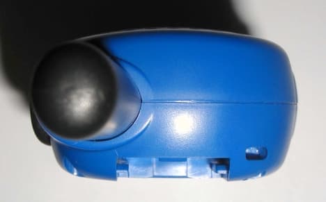
Click to zoom
Application Details
- Equipment Class
- FRF - Part 95 Family Radio Face Held Transmitter
- Date of Grant
- May 21, 2002
- Application Purpose
- Original Equipment
- Date of Application
- Apr 02, 2002
- Frequency Range
- 462.56250000 - 467.71250000
- Company
- RadioShack Corporation
- Country
- United States
Documents & Files
Document Text
Text extracted from the exhibit documents filed with the FCC. Open a document above to read the original.
Users Manual
DRAFT OF BLISTER CARD OF 21-1849 March 13, 2002 Prepared By Headline I & C Ltd., These radios make keeping in touch fun and easy. Whether playing inside or outdoors, these license-free, 2w ay radios fit nicely in the palm of your hand. You can talk to your friends in the next room, next door and around the neighborhood. Use them at shopping malls, amusement parks or sports events to stay in touch w ith family and friends. These cool radios feature “auto- squelch”, w hich means you w ill not hear anything on the channel unless someone is transmitting nearby on the same channel. The radio automatically sw itches to sleep mode if not used for six seconds, and w akes up w hen it receives a transmission or you press any key. Installing batteries, Your radio uses three “AAA” batteries for pow er, For the best performance, w e recommend RadioShack alkaline batteries. Note ; You can also use NI-CD/Ni-MH rechargeable batteries in the radio and recharge them, using a separate battery charger, available at your local RadioShack store. 1. The w ay to exist the menu, a) w hen press PTT button b) w hen press Call button c) w hen no button touching for 30 seconds d) w hen go through the end of the menu. 2. Install the batteries, matching the polarity symbols(+ and -) inside. 3. Replace the cover The radio’s range decreases as the battery pow er decreases, To ensure maximum range, keep fresh batteries in the radio. WARNING : Dispose of old batteries promptly and properly. Do not burn or bury them. CAUT ION : Do not mix old and new batteries, different types of batteries(standard, alkaline or rechargeable) or rechargeable batteries of different capacities. Using the radio 1. To turn on the radio, press pow er button for 2 seconds 2. Adjust the volume to the desired listening level by pressing up/dow n button. 3. To enter to the memu mode and select CH, press Mode button once and then press up/dow n button for the channel you w ant. 4. To make the melody ON or OFF, press Mode button tw o times and then press up/dow n button. 5. To make confirmation tone ON or OFF, press Mode button three times and then press up/dow n button. 6. To talk, hold dow n PTT. When the TX/BATT indicator lights, speak in to the microphone. Note : If Low Battery blinks w hen PTT is not held dow n, replace the batteries. When you finish speaking, release PTT. Talk confirmation You can set the radio so a confirmation tone sounds w hen you release PTT. T he tone alerts another person you are talking to that you have finished talking. T he belt c lip To attach the belt clip, slide it dow n until it locks into place. To remove the belt clip, pull the tab and slide the belt clip up. Using a wrist strap You can attach an optional w rist strap or pager chain(neither supplied) to the w rist strap hole behind OFF. Auto pow er save Your radio saves battery life by reducing the pow er the radio uses until it receives a signal or you press a key. Because the receiv ing radio might be suing pow er save mode, w ait about 5 seconds after pressing PTT to allow the receiving radio to come to full pow er before speaking into the microphone. FCC information Important : Do not open your radio to make any internal adjustments. Your radio is set up to transmit a regulated signal on an assigned frequency. It is against the law to alter or adjust the setting s inside the radio to exceed those limitations. Any adjustments made to you radio mist be made by a qualified technician using the proper test equipment. To be safe and sure: Never open your radio’s case. Never change or replace anything in your radio except the batteries. Your radio might cause T V or radio interference even w hen it is operating properly. To determine w hether your radio is causing the interference, turn it off. if the interference goes aw ay, your radio is causing it. Try to eliminate the interference by: Moving your radio aw ay from the receiver. Calling your local RadioShack store for help. Using your transceiver as described in this manual exposes you to FR energy w ell below the FCC’s recommended limits. This device complies w ith Part 15 of the FCC Rules, Operation is subject to the follow ing tw o conditions : (1) T his device may not cause harmful interference, and (2) this device mist accept any interference received, including interference that may cause undesired operation. Care To enjoy your radio for a long time, keep the radio dry. If it gets w et, w ipe it dry immediately. Use and store the radio only in normal temperature environments. Handle the radio gently and carefully. Do not drop it. Keep the radio aw ay from dust and dirt. Wipe the radio w ith a damp clith occasionally to keep it looking new. Modifying or tampering w ith the radio’s internal components can cause a malfunction and might invalidate the radio’s w arranty and void your FCC authorization to operate it. If your radio is not performing as it should, take it to your local RadioShack store for assistance. Spec ific ations Channel 14 Pow er output 500mW ERP operating temperature - 4 to + 122’f(-20 to +50’c) Frequency 462.5625 ~ 467.7125MHz. Weight (w ith batteries) 4.2 oz. (119g) Battery Life : Transmit mode Standby mode Alkaline 3 hours(1050mAh) Alkaline 18 hours(1050mAh) Ni-Cd 1 hours(300mAh) Ni- Cd 5 hours(300mAh) Ni-MH 2 hours(600mAh) Ni-MH 10 hours(600mAh) Specifications are typical : individual units might vary. Specifications are subject to change and improvement w ithout notice
External Photos
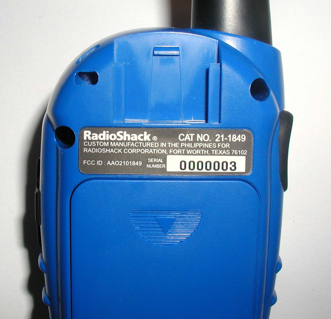
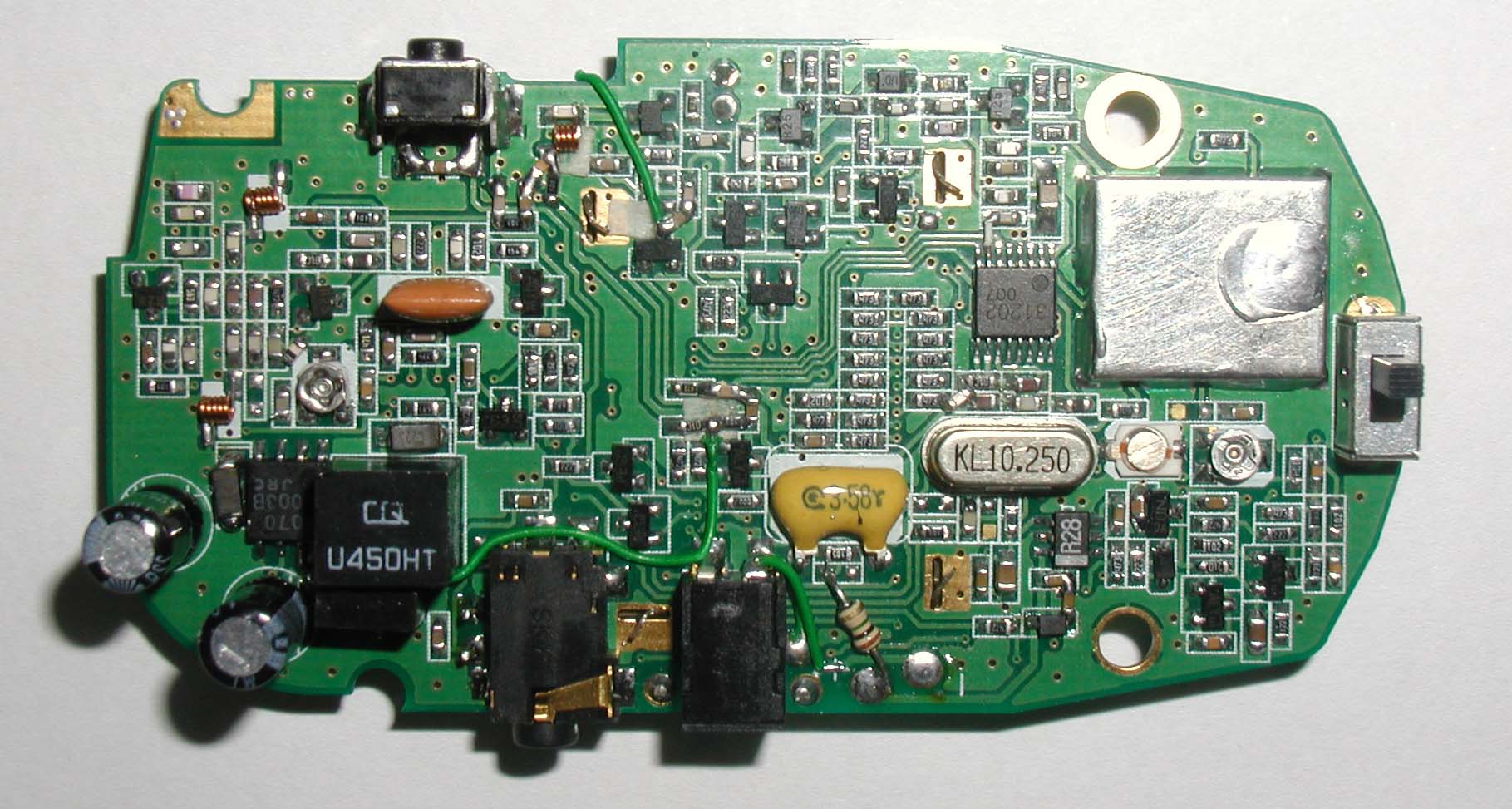
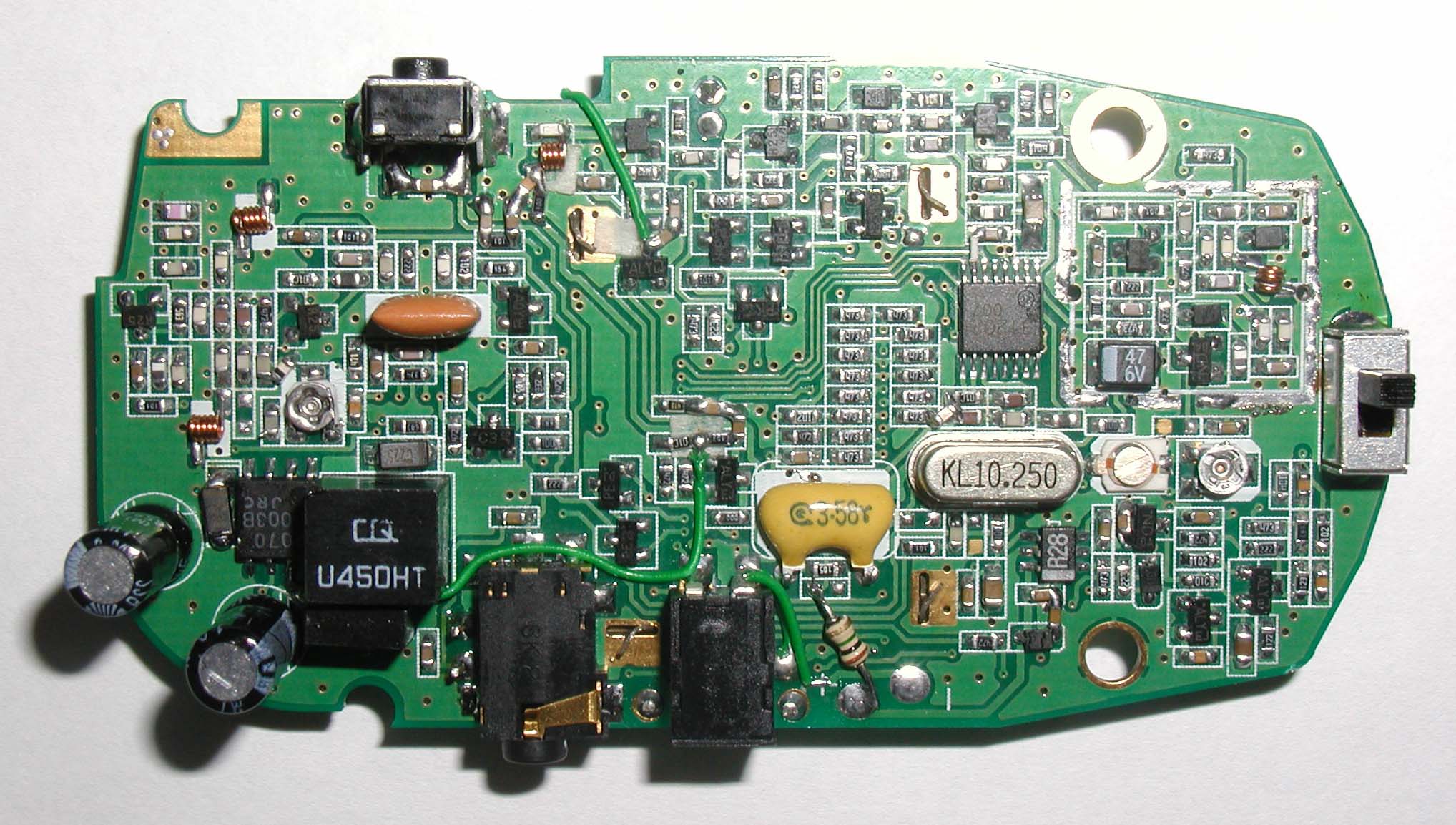
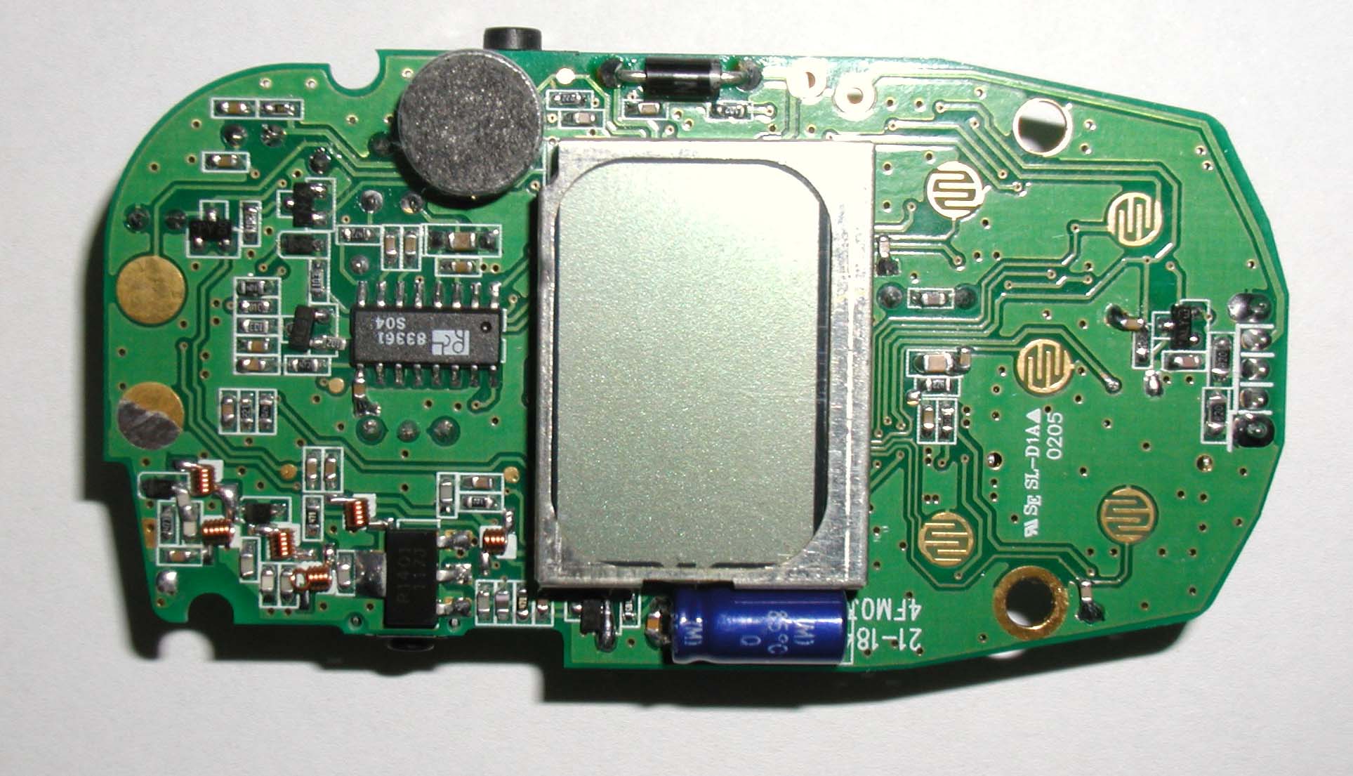
Front View Rear View Rear View (Charger Compartment) Left Side View Right side View Top View Botto m View
Operational Description
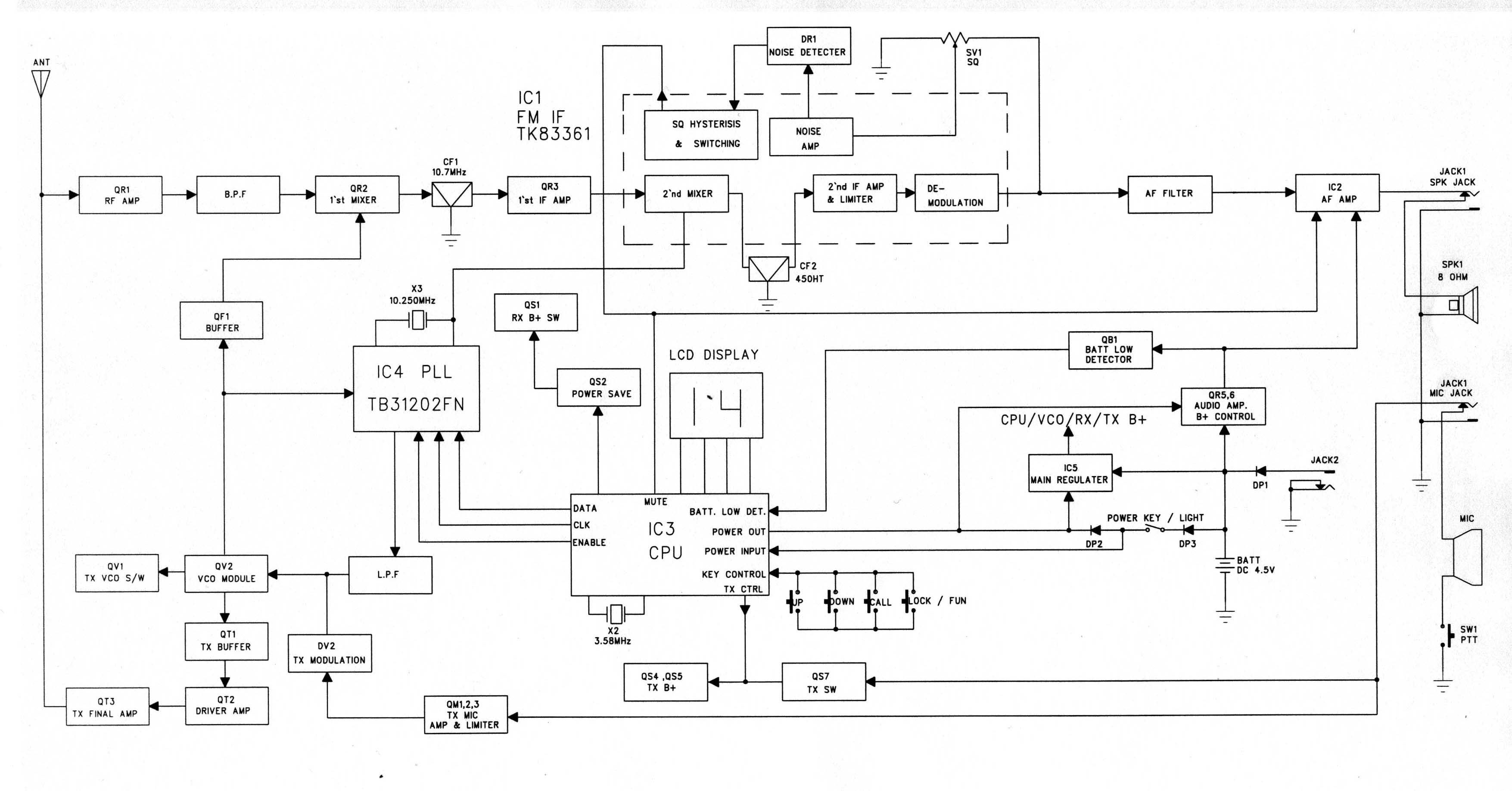
Alignment instructions WARNING Any repairs or adjustments should be made under the supervision of a qualified radio-telephone technician. TRANSMITTER 1. Power Supply Voltage The Power supply voltage should be set for 4.5 VDC measured at the radio during transmit. Periodically check the power supply voltage during the alignment procedure. 2. Frequency Setting A. Connect a frequency counter or Communications Service Monitor to the antenna connector through and RF power attenuator (10 watt minimum rating, 20 dB minimum attenuation). B. Depress the PTT switch. C. Adjust the CTX1 trimmer capacitor such that the output frequency is equal to the channel frequency with a maximum error of +/- 300 Hz. D. Release the PTT switch. 3. Output Power Alignment. A. Set the power supply voltage for 4.5 VDC. B. Connect a Communications Service Monitor or a wattmeter and dummy load to the antenna connector. C. Depress the PTT switch. D. To be convinced for 0.5 Watt output power with a maximum error of +/- 0.05Watt. E. Release the PTT switch. 4. Deviation Adjustment. A Connect an audio generator to the microphone jack JIG. The audio frequency should be set at 1 KHz. B. Connect an FM deviation meter or Communications Service Monitor to the antenna connector through an RF power attenuator (10 watt minimum rating, 20 dB minimum attenuation). Set the monitor to read peak deviation. C. Depress the PTT switch. D. Adjust the audio generator level 100 mV rms. E. Adjust SV3 for +/- 2.2 KHz maximum deviation. F. Release the PTT switch.
Test Report
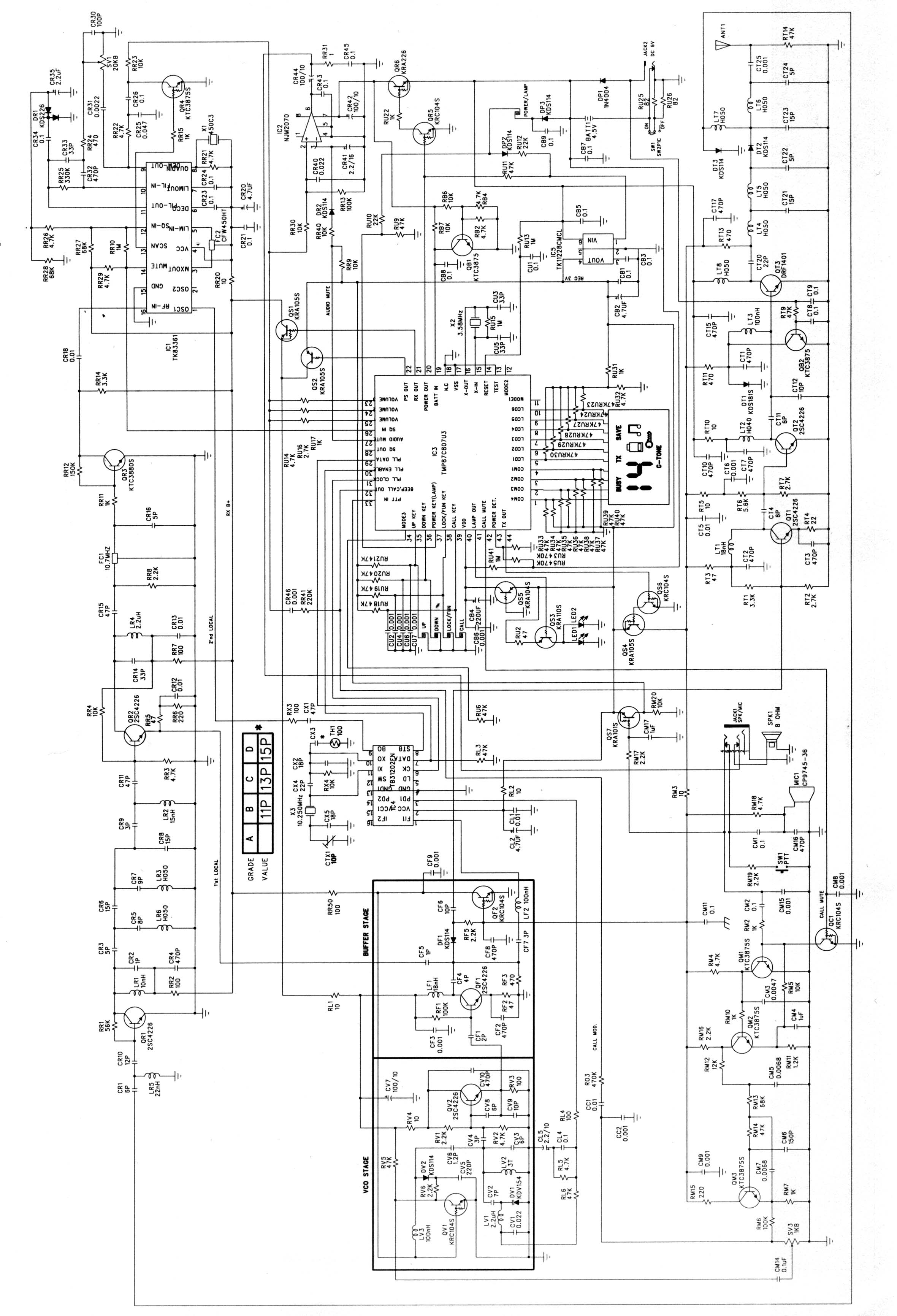
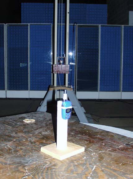
A. INTRODUCTION The following data are submitted in connection with this request for type certification of the 21-1849 transceiver in accordance with Part 2, Subpart J of the FCC Rules. The 21-1849 is a portable, battery operated, UHF, frequency modulated transceiver intended for 12.5 kHz channel family radio service applications in the 462.5625-467.7125 MHz band. It operates from a nominal 4.5 Vdc battery supply. MFR rated output power is 0.5 watts ERP. B. GENERAL INFORMATION REQUIRED FOR TYPE CERTIFICATION (Section 2.1033 of the Rules) 1. Name of applicant: Radio Shack Corporation 2. Identification of equipment: FCC ID: AAO2101849 a. The equipment identification label is submitted as a separate exhibit. b. Photographs of the equipment are submitted as a separate exhibit. 3. Quantity production is planned. 4. Technical description: a. 11k0F3E emission b. Frequency range: 462.5625 - 467.7125 MHz. c. Operating power of transmitter is fixed at the factory at less than 0.5 W ERP. d. Maximum power permitted is 0.5 watts, and the 21-1849 fully complied with that power limitation. e. The dc voltage and dc currents at final amplifier: Collector voltage: 4.4 Vdc Collector current: 0.52 A f. Function of each active semiconductor device: See Appendix 1. g. Complete schematic diagram is submitted as a separate exhibit. h. A draft instruction manual is submitted as a separate exhibit. i. The transmitter tune-up procedure is submitted as a separate exhibit. B. GENERAL INFORMATION (continued) j. A description of circuits for stabilizing frequency is included in Appendix 2. k. A description of circuits and devices employed for suppression of spurious radiation and for limiting modulation is included in Appendix 3. l. Not applicable. 5. Data for 2.1046 through 2.1057 follow this section. C. RF Power Output (Section 2.1046 of the Rules) The 21-1849 has a permanently attached built-in antenna without provisions for a coaxial connector. RF power output was determined by substitution. TABLE 1 Operating Freq., MHz Power watts into a dipole antenna 462.5625 0.49 D. MODULATION CHARACTERISTICS (Section 2.1047 of the Rules) 1. A curve showing frequency response of the transmitter is shown in Figure 1. Reference level was audio signal output from a Boonton 8220 modulation meter with one kHz deviation. Audio output was measured with an Audio Precision System One integrated test system. 2. Modulation limiting curves are shown in Figure 2, using a Boonton 8220 modulation meter. Signal level was established with a Audio Precision System One integrated test system. The curves show compliance with paragraphs 2.987(b). 3. Figure 3 is a graph of the post-limiter low pass filter which provides a roll-off of 60Logf/3 dB where f is audio frequency in kHz. Measurements were made following EIA RS-152B with an Audio Precision System One integrated test system on the Boonton 8220 modulation meter audio output. 2 4. Occupied Bandwidth (Section 2.1047 and 95.629(a)of the Rules) Figure 4 is a plot of the sideband envelope of the transmitter output taken with a Tektronix 494P spectrum analyzer. Modulation corresponded to conditions of 2.1049(c)(1) and consisted of 2500 Hz tone at an input level 16 dB greater than that necessary to produce 50% modulation at 1997 Hz, the frequency of maximum response. Emission designator: (2M + 2D) (2 x 3 kHz) + (2 x 2.5 kHz) = 11k0F3E 3 FIGURE 1 MODULATION FREQUENCY RESPONSE MODULATION FREQUENCY RESPONSE FCC ID: AAO2101849 FIGURE 1 4 FIGURE 2 AUDIO LIMITER CHARACTERISTICS AUDIO LIMITER CHARACTERISTICS FCC ID: AAO2101849 FIGURE 2 5 FIGURE 3 AUDIO LOW PASS FILTER RESPONSE AUDIO LOW PASS FILTER RESPONSE FCC ID: AAO2101849 FIGURE 3 6 FIGURE 4 OCCUPIED BANDWIDTH ATTENUATION IN dB BELOW MEAN OUTPUT POWER Required On any frequency more than 50% up to and including 100% of the 25 authorized bandwidth, 12.5 kHz (6.25-12.5 kHz) On any frequency more than 100%, up to and including 250% of the 35 authorized bandwidth (12.5-31.25 kHz) On any frequency removed from the assigned frequency by more 43+10LogP = 40 than 250% of the authorized (P = 0.49) bandwidth (over 31.25 kHz) OCCUPIED BANDWIDTH FCC ID: AAO2101849 FIGURE 4 7 D. MODULATION CHARACTERISTICS (Continued) The plots are within FCC limits. The horizontal scale frequency) is 10 kHz per division and the vertical scale amplitude) is a logarithmic presentation equal to 10 dB per division. E. SPURIOUS EMISSIONS AT THE ANTENNA TERMINALS The 21-1849 has a permanently attached antenna. There is no connector for an external antenna. Therefore, no antenna terminal conducted measurements were made. F. MEASUREMENTS OF SPURIOUS RADIATION (Section 2.1053, 95.635(b)(7) of the Rules) Measurements of radiated spurious emissions from the 21-1849 were made by substitution with a Tektronix 494P spectrum analyzer using Singer DM-105 for the measurements to 1 GHz, and EMCO 3115 horn to 4.8 GHz. The transmitter was located in an open field 3 meters from the test antenna. Supply voltage was a power supply with a terminal voltage under load of 4.5 Vdc. The transmitter and test antennae were arranged to maximize pickup. Both vertical and horizontal test antenna polarization were employed. Measurements were made from the lowest frequency generated within the unit (10.25 MHz), to 10 times operating frequency. Data after application of antenna factors and line loss corrections are shown in Table 2. 8 TABLE 2 TRANSMITTER CABINET RADIATED SPURIOUS 462.5625 MHz, 4.5 Vdc, 0.49 watts Spurious dB Below Frequency Carrier ___MHz___ Reference 462.563 0 925.127 53H 1387.693 53V 1850.251 54H 2312.811 49H 2775.376 50H 3237.936 45H 3700.498 54V 4163.058 55H 4625.623 57V Required: 43+10 Log(P) = 40 All other spurious from 20.95 MHz to the tenth harmonic were 20 dB or more below FCC limit. 9 G. FREQUENCY STABILITY (Section 2.1055 and 95.621(b) of the Rules)) Measurement of frequency stability versus temperature was made at temperatures from -20 o C to +50 o C. At each temperature, the unit was expos…
Text truncated - open the document above for the full version.
Contact Information
Applicant
Elizabeth Granados(Regulatory Affairs Manager)
Technical Contact
Hyak Laboratories, Inc.Rowland S Johnson
[email protected](703) 451-1188
7011 Calamo St., Suite 107 · Springfield, Virginia · United States
Non-Technical Contact
Hyak Laboratories, Inc.Georgia Hall
[email protected](703) 451-1188
Test Firm
Carl T. Jones CorporationCarl Jones
Technical Specifications
| # | Rule Parts | Frequency Range | Power Output | Emission | Tolerance |
|---|---|---|---|---|---|
| 1 | 95 | 462.5625 MHz - 467.7125 MHz | 500.00 mW | 11K0F3E | 0.0002500000 ppm |
Other Applications from RadioShack Corporation

AAO2302500
Feb 10, 2015Bluetooth Power Bank
Equipment Class
DXX - Part 15 Low Power Communication Device Transmitter
AAO4300124C
May 02, 2013900MHz Wireless Intercom
Equipment Class
DXT - Part 15 Low Power Transceiver, Rx Verified
AAO1200876
Nov 30, 2011Universal FM Transmitter
Equipment Class
DXX - Part 15 Low Power Communication Device Transmitter
AAO1200962
Aug 02, 2011Universal FM Transmitter
Equipment Class
DXX - Part 15 Low Power Communication Device Transmitter
AAO1500044T
Apr 02, 20112.4GHz Digital Wireless Rear Speaker Kit - Transmitter
Equipment Class
DSS - Part 15 Spread Spectrum Transmitter