AAO2101860Face Held Family Radio
RadioShack Corporation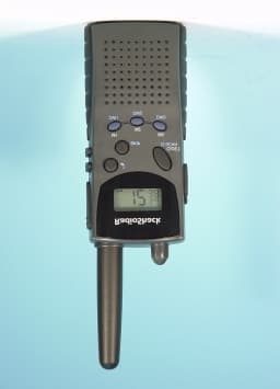
Click to zoom
Application Details
- Equipment Class
- FRF - Part 95 Family Radio Face Held Transmitter
- Date of Grant
- Mar 06, 2001
- Application Purpose
- Original Equipment
- Date of Application
- Dec 12, 2000
- Equipment Note
- Face Held Family Radio
- Frequency Range
- 462.56250000 - 467.71250000
- Company
- RadioShack Corporation
- Country
- United States
Documents & Files
Document Text
Text extracted from the exhibit documents filed with the FCC. Open a document above to read the original.
Users Manual
TEKCOM Industries Limited Page 1 of 6 OWNER’S MANUAL FRS RADIO 21-1860 INTRODUCTION Your RadioShack FRS radio is a portable, easy-to-use, two-way radio that you can carry almost anywhere. Use it at shopping malls, amusement parks, sports events, or at the beach to contact family and friends, or for vital communications in a neighborhood watch. Your radio has 14 channels and 38 different quiet codes. If someone else is using the channel you selected and you do not want to hear that person, select another channel or use the quiet feature. You can talk with a person who has a FRS radio if both radios are tuned to the same channel and quiet code. Your radio also has one touch access key for 3 pre-programmed or user preferable FRS channel. The radio can auto dual watch between the operation channel and user preset channel. Your radio has auto-squelch, which means you will not hear anything on a channel unless someone is transmitting nearby on the same channel. You can turn off auto-squelch to hear weaker, distant transmissions. Also, if the radio is idle for 2 hours, it automatically shuts off. It turns on again when you press any key. You can connect an optional speaker/microphone and earphone, charger (not supplied) to the radio. And, the belt clip lets you take your radio almost anywhere. USING THE RADIO A. DISPLAY Your radio comes with a multifunction backlighted display. By pressing any button except the CALL and PTT, the backlight will illuminate for 7 seconds. 1. Shows the selected channel number. TEKCOM Industries Limited Page 2 of 6 2. Shows the selected privacy code number. 3. Shows the selected memory channel number. 4. “QUIET”: Displays when the QUIET mode is enabled. 5. “BUSY” : Displays when a call is being received. 6. “ ” : Displays when your radio is transmitting or the CALL button is pressed. 7. “FUNC” : Displays when the secondary function is enabled. 8. “SCAN” : Displays when the scan mode is activated. 9. “DUAL” : Displays when the dual-watch function is activated. 10. “ ” : Displays when the working channel is set to be skipped. 11. “ ”: Indicates the batteries are low. Replace the batteries when it appears. 12. “ ”: Displays when the key tone function is activated. 13. “ ”: Displays when the keypad lock is activated. 14. “C-TONE”: Display when the over-tone function is activated. B. FUNCTION AND LOCATION OF THE CONTROLS 1. “ON/OFF” Volume Control. TEKCOM Industries Limited Page 3 of 6 In “OFF” position, your transceiver is off. Rotate this control clockwise to turn on your radio and adjusts the volume, until you get a comfortable listening level. 2. CH /Key Tone Button Press CH to move one channel higher. Press and hold CH for more than 1.5sec to enter into the scan upwardly mode. Press CH will change the scanning direction. Press FUNC key and hold for less than 1.5 sec, then press CH key to activate or deactivate the Key Tone function. Icon “ ” will be shown if activated. 3. CH / Skip / Automatic Shut Off Button Press CH to move one channel down. Press and hold CH for more than 1.5sec to enter into the scan downwardly mode. Press CH will change the scanning direction. Skip User can choose a desired channel from being scanned. Press CH or to go to the desired channel. Press FUNC key and hold for less than 1.5 sec, then press CH key to skip this channel from scanning. Icon “ " ” is on to indicate this working channel is set to be skipped. Automatic Shut Off Button Press and hold the CH while turning on the radio will enable or disable the automatic shut off timer. The display will show “AP ON ” when the timer is activated, or “AP OF ” when deactivated. The timer automatically turns off the unit when it is idle for 2 hours. 4. QUIET /QUIET Scan Button Press QUIET button to enable or disable the QUIET privacy mode operation. a) Hold down QUIET button for 2 seconds until QUIET is displayed and the quiet code flashes. b) Repeatedly press (or hold down) CH or CH until you see the code number you want to use. c) Press QUIET button to store the code. To turn on the quiet feature, press QUIET. QUIET appears. To turn off the feature, press QUIET until QUIET disappears. Note: We recommend that you select a quiet code from the range 7-30. If you select a code below or above that range, you must wait 1 to 2 seconds after holding down PUSH-TO-TALK before you start talking. QUIET Scanning TEKCOM Industries Limited Page 4 of 6 Press FUNC key for less than 1.5 sec, and follow by QUIET key to enter into the QUIET Scan mode, and icons of “ SCAN” and “ QUIET” will be lightened on LCD. When received the same QUIET code, the scanning stops and will keep scanning after the signal disappears. Press any key will exit and return to the normal working channel. 5. M1 (M2 or M3)/ Dual Watch Press M1 (M2 or M3) to switch the unit to the channel stored at this location. Dual Watch It can be activated or deactivated by pressing the FUNC key for less than 1.5sec and follow by M1 (M2 or M3). ‘DUAL’ icon will be shown on the LCD if activate. During Dual-Watching, upon receiving a signal from the normal working channel or M1 (M2 or M3) channel, the unit will stop at that channel. If the signal is gone, the unit will resume Dual-Watch. 6. Push-To-Talk button / Keylock /C-Tone To talk, hold down the Push-To-Talk. Speak into the microphone in a normal tone of voice when the icons is displayed. When you finish speaking, release the Push-To-Talk button. Your can also lock your radio setting to avoid accidental pressing of keys by activating the keypad lock. Press and hold the FUNC button, then press the PTT button to activate or deactivate the keypad lock. Press and hold the Push-To-Talk while turning on the radio will enable or disable the courtesy tone (C-Tone) function. 7. MON/FUNC Button To hear everything happening on a channel, including weak transmission, hold down MON/FUNC button for more than 1.5 sec. Re lease the MON/FUNC button to turn the auto- squelch back on. 8. CALL/MCU Reset Button You can caus…
Text truncated - open the document above for the full version.
External Photos
Front View Back View
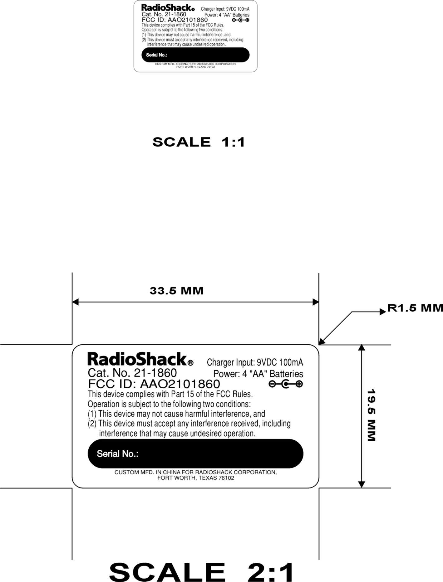
ID Label/Location Info
FCC ID: AAO2101860
Internal Photos
PCB Track Side PCB – Component Side
Operational Description
TEKCOM Industries Limited Page 1 of 7 THEORY OF OPERATION 21-1860 This PLL controlled FRS transceiver provides accurate and stable operation. The basic functions consist of 8 main sections: ! Power ! Receiver Stage ! Squelch Control ! Transmit Stage ! VCO and PLL ! Microcontroller ! CTCSS ! CALL ! Power The unit is powered with 6.0V (4 × AA type) Alkaline type or 4.8V (4 × 1.2V) Ni-Cd type batteries. The power is spread into four sections. 1 The power for the low battery detect circuitry. This circuit is used to detect the battery capacity and turn on the low battery icon accordingly. 2 The power for the RF-power amplifier. 3 The power for the Audio amplifier section. 4 The 6.0V or 4.8V is regulated to 3.5V by IC6 TK11335 for the power supply to the MCU and its related circuitry. Under the MCU control, Q2 composes as a power switch for transmit and receive circuitry. Q1 and Q6 are for the power supply to VCO and PLL circuitry. For power saving purpose, Q1 and Q6 are turned on and off in a ratio of 1:3, It is 250msec on and 750msec off. ! Receive Stage RF signal is received through the antenna and is passed onto a low pass filter network and amplified by Q101. This allows only the required band signal to pass through the band pass filter (BPF) and the second stage RF amplifier Q102. The mixer Q103 converts the incoming signal down to 21.7MHz. These signals again pass to a 21.7MHz XTAL band pass filter F101. This gives a better channel selectivity. The selected 21.7MHz XTAL signal is amplified by IF amplifier Q104 before it is passed to the second converter IC101 MC3361. This converts the 21.7MHz signal down to 450kHz. This 450kHz signal is sent to discriminator after passed through F102 filter. The signal is demodulated, and outputs an audio signal. The detected audio signal passes through Audio Amplifier unit IC2 LM324, the 300Hz high pass filter and volume control VR1, a final audio amplifier IC106 NJM2070, and then to the speaker. When a call signal is received, the signal is extracted by IC3 LM324 when a call signal is detected. MCU then generates a buzz sound to alert the user. ! Squelch Control TEKCOM Industries Limited Page 2 of 7 Squelch control circuitry consists of IC101 MC3361 and its related circuit. The squelch signal output from IC101 pin 9 pass through filter amplifier circuit composed by pin 10 and pin 11. The signal is detected by D104. D104 established a control voltage to the squelch input: pin 12, 14 of IC101. VR102 is used to control the threshold of the squelch (squelch sensitivity) when pin 12 of IC101 is larger than 0.7V. Pin 14 of IC101 is output a Hi to MCU IC1 pin 50 to indicate an incoming signal is detected. ! Transmit Stage When the PTT sw itch is pressed, the transceiver is sw itched into transmit mode through the TX/RX exchange control D102, D103. MCU turns on the power to the transmitter. The voice is picked up by the condenser MIC and passes through the 300Hz high pass filter IC103 NJM3403 and is amplified by IC105 LM324 MIC amplifier circuit, and adjusted by VR101 to obtain a proper audio frequency response. The signal modulates with the carrier in the form of FM modulation. The modulated signal from the VCO goes into the power amplifier unit which consists of a buffer amplifier Q109, a driver amplifier Q108 and the RF power amplifier Q106. The signal then is finally radiated out through antenna. The unit will also be switched into transmit mode when the CALL button is pressed. A dual tone signal of 1.2KHz and 600Hz will be fed into the transmitter for transmission. ! VCO and PLL PLL circuitry is composed by IC102 M64082, the frequency synthesizer PLL and VCO. The channel information from the MCU is sent to the shift register in IC102 from pin 2. A control voltage is generated through the low pass filter to the VCO from pin 8 and is used to control RF frequency from Q112. Q107 is the RX/TX exchange switch. RF signal from the VCO passes through the buffer amplifier Q112 and then is fed back into PLL pin 6 of IC102. IC102 pin 10 output a lock detected to indicate the VCO frequency is in “Lock”. In receive mode, the signal is fed to the receiver first mixer Q103, and generate the first intermediate frequency (IF). In transmit mode, this signal modulation with the audio signal or call signal and is passed through to transmit power amplifier unit for transmission. ! Microcontroller The Microcontroller μ PD789405 is the main control of the whole transceiver unit. It is also used to drive the LCD to show the status of the unit. On the LCD, there is current working channel display, transmit indication, receive indication, and low battery indication. The MCU scans the keypad to detect key pressed and released, then execute the function accordingly. ! CTCSS The CTCSS consists of transmitter and receiver section. In CTCSS transmission, a CTCSS signal is added to the audio and modulated for transmission. MCU pin OUT1, OUT2, OUT3 and OUT4 output a 16-stage of the digital values. These digital values then are passed through a digital to analog converters R1 and R2. The output is a step waveform, and then is filtered by a low pass filter and mixed with the audio. The receiver section consists of a CTCSS decoder circuit which is used to separate the audio signal and the CTCSS signal for the existing CTCSS signal. The CTCSS signal is filtered and amplified by IC101 MC3361 and reshaped as a square TEKCOM Industries Limited Page 3 of 7 wave by IC3 LM324. The signal then is input to the MCU and is determined the CTCSS signal value for the valid CTCSS receive. ! CALL When the CALL button is pressed, the transceiver is sw itched into transmit mode through the MCU and Q105 control. IC104 CD4001 generates a dual tone signal of 1.2kHz and 600Hz which is controlled by MCU. This dual tone signal of 1.2kHz and 600Hz signal is amplified in the MIC amplifier unit and modulated for transmission. TEKCOM Industries Limited Page 4 of 7 TROUBLE SHOOTING Before troubleshooting, prepare you…
Text truncated - open the document above for the full version.
RF Exposure Info
TEKCOM Industries Limited Page 1 of 6 OWNER’S MANUAL FRS RADIO 21-1860 INTRODUCTION Your RadioShack FRS radio is a portable, easy-to-use, two-way radio that you can carry almost anywhere. Use it at shopping malls, amusement parks, sports events, or at the beach to contact family and friends, or for vital communications in a neighborhood watch. Your radio has 14 channels and 38 different quiet codes. If someone else is using the channel you selected and you do not want to hear that person, select another channel or use the quiet feature. You can talk with a person who has a FRS radio if both radios are tuned to the same channel and quiet code. Your radio also has one touch access key for 3 pre-programmed or user preferable FRS channel. The radio can auto dual watch between the operation channel and user preset channel. Your radio has auto-squelch, which means you will not hear anything on a channel unless someone is transmitting nearby on the same channel. You can turn off auto-squelch to hear weaker, distant transmissions. Also, if the radio is idle for 2 hours, it automatically shuts off. It turns on again when you press any key. You can connect an optional speaker/microphone and earphone, charger (not supplied) to the radio. And, the belt clip lets you take your radio almost anywhere. USING THE RADIO A. DISPLAY Your radio comes with a multifunction backlighted display. By pressing any button except the CALL and PTT, the backlight will illuminate for 7 seconds. 1. Shows the selected channel number. TEKCOM Industries Limited Page 2 of 6 2. Shows the selected privacy code number. 3. Shows the selected memory channel number. 4. “QUIET”: Displays when the QUIET mode is enabled. 5. “BUSY” : Displays when a call is being received. 6. “ ” : Displays when your radio is transmitting or the CALL button is pressed. 7. “FUNC” : Displays when the secondary function is enabled. 8. “SCAN” : Displays when the scan mode is activated. 9. “DUAL” : Displays when the dual-watch function is activated. 10. “ ” : Displays when the working channel is set to be skipped. 11. “ ”: Indicates the batteries are low. Replace the batteries when it appears. 12. “ ”: Displays when the key tone function is activated. 13. “ ”: Displays when the keypad lock is activated. 14. “C-TONE”: Display when the over-tone function is activated. B. FUNCTION AND LOCATION OF THE CONTROLS 1. “ON/OFF” Volume Control. TEKCOM Industries Limited Page 3 of 6 In “OFF” position, your transceiver is off. Rotate this control clockwise to turn on your radio and adjusts the volume, until you get a comfortable listening level. 2. CH /Key Tone Button Press CH to move one channel higher. Press and hold CH for more than 1.5sec to enter into the scan upwardly mode. Press CH will change the scanning direction. Press FUNC key and hold for less than 1.5 sec, then press CH key to activate or deactivate the Key Tone function. Icon “ ” will be shown if activated. 3. CH / Skip / Automatic Shut Off Button Press CH to move one channel down. Press and hold CH for more than 1.5sec to enter into the scan downwardly mode. Press CH will change the scanning direction. Skip User can choose a desired channel from being scanned. Press CH or to go to the desired channel. Press FUNC key and hold for less than 1.5 sec, then press CH key to skip this channel from scanning. Icon “ " ” is on to indicate this working channel is set to be skipped. Automatic Shut Off Button Press and hold the CH while turning on the radio will enable or disable the automatic shut off timer. The display will show “AP ON ” when the timer is activated, or “AP OF ” when deactivated. The timer automatically turns off the unit when it is idle for 2 hours. 4. QUIET /QUIET Scan Button Press QUIET button to enable or disable the QUIET privacy mode operation. a) Hold down QUIET button for 2 seconds until QUIET is displayed and the quiet code flashes. b) Repeatedly press (or hold down) CH or CH until you see the code number you want to use. c) Press QUIET button to store the code. To turn on the quiet feature, press QUIET. QUIET appears. To turn off the feature, press QUIET until QUIET disappears. Note: We recommend that you select a quiet code from the range 7-30. If you select a code below or above that range, you must wait 1 to 2 seconds after holding down PUSH-TO-TALK before you start talking. QUIET Scanning TEKCOM Industries Limited Page 4 of 6 Press FUNC key for less than 1.5 sec, and follow by QUIET key to enter into the QUIET Scan mode, and icons of “ SCAN” and “ QUIET” will be lightened on LCD. When received the same QUIET code, the scanning stops and will keep scanning after the signal disappears. Press any key will exit and return to the normal working channel. 5. M1 (M2 or M3)/ Dual Watch Press M1 (M2 or M3) to switch the unit to the channel stored at this location. Dual Watch It can be activated or deactivated by pressing the FUNC key for less than 1.5sec and follow by M1 (M2 or M3). ‘DUAL’ icon will be shown on the LCD if activate. During Dual-Watching, upon receiving a signal from the normal working channel or M1 (M2 or M3) channel, the unit will stop at that channel. If the signal is gone, the unit will resume Dual-Watch. 6. Push-To-Talk button / Keylock /C-Tone To talk, hold down the Push-To-Talk. Speak into the microphone in a normal tone of voice when the icons is displayed. When you finish speaking, release the Push-To-Talk button. Your can also lock your radio setting to avoid accidental pressing of keys by activating the keypad lock. Press and hold the FUNC button, then press the PTT button to activate or deactivate the keypad lock. Press and hold the Push-To-Talk while turning on the radio will enable or disable the courtesy tone (C-Tone) function. 7. MON/FUNC Button To hear everything happening on a channel, including weak transmission, hold down MON/FUNC button for more than 1.5 sec. Re lease the MON/FUNC button to turn the auto- squelch back on. 8. CALL/MCU Reset Button You can caus…
Text truncated - open the document above for the full version.
Test Report
ENGINEERING STATEMENT For Type Certification of Radio Shack; a Division of Tandy Corporation Model No: 21-1860 FCC ID: AAO2101860 I am an Electronics Engineer, a principal in the firm of Hyak Laboratories, Inc., Springfield, Virginia. My education and experience are a matter of record with the Federal Communications Commission. Hyak Laboratories, Inc. has been authorized by Radio Shack; a Division of Tandy Corporation, to make type certification measurements on the 21-1860 transceiver. These tests made by me or under my supervision in our Springfield laboratory. Test data and documentation required by the FCC for type certification are included in this report. The data verifies that the above mentioned transceiver meets FCC requirements type certification is requested. ______________________________ Rowland S. Johnson Dated: November 28, 2000 A. INTRODUCTION The following data are submitted in connection with this request for type certification of the 21-1860 transceiver in accordance with Part 2, Subpart J of the FCC Rules. The 21-1860 is a mobile, UHF, frequency modulated transceiver intended for 12.5 kHz channel family radio service applications in the 462.5625-467.7125 MHz band. It operates from a 6 Vdc supply. Output power rating is 0.5 watts ERP. B. GENERAL INFORMATION REQUIRED FOR TYPE CERTIFICATION (Paragraph 2.983 of the Rules) 1. Name of applicant: Radio Shack, a Div. of Tandy Corp. 2. Identification of equipment: FCC ID: AAO2101860 a. The equipment identification label is a separate exhibit. b. Photographs of the equipment are included as a separate exhibit. 3. Quantity production is planned. 4. Technical description: a. 11k0F3E emission b. Frequency range: 462.5625 - 467.7125 MHz. c. Operating power of transmitter is fixed at the factory 0.5 W ERP. d. Maximum power permitted is 0.5 watts, and the 21- 1860 fully complied with that power limitation. e. The dc voltage and dc currents at final amplifier: Collector voltage: 5.9 Vdc Collector current: 0.17 mA f. Function of each active semiconductor device: See Appendix 1. g. Complete circuit diagram is submitted as a separate exhibit. h. A draft instruction book is submitted as a separate exhibit. i. The transmitter tune-up procedure is included as a separate exhibit. 2 B. GENERAL INFORMATION REQUIRED FOR TYPE CERTIFICATION (continued) j. A description of circuits for stabilizing frequency is included in the Theory of Operation. k. A description of circuits and devices employed for suppression of spurious radiation and for limiting modulation is included in the Theory of Operation. l. Not applicable. 5. Data for 2.985 through 2.997 follow this section. C. RF_Power_Output (Paragraph 2.985(a) of the Rules) The 21-1860 has a permanently attached built in antenna without provisions for a coaxial connector. Therefore RF power output was determined by substitution. TABLE 1 Operating Freq., MHz Power watts into a dipole antenna 462.5625 0.47 D. MODULATION CHARACTERISTICS 1. A curve showing frequency response of the transmitter is shown in Figure 1. Reference level was audio signal output from a Boonton 8220 modulation meter with one kHz deviation. Audio output was measured with a Audio Precision System One integrated test system. 2. Modulation limiting curves are shown in Figure 2, using a Boonton 8220 modulation meter. Signal level was established with a Audio Precision System One integrated test system. The curves show compliance with paragraphs 2.987(b). 3 D. MODULATION CHARACTERISTICS (continued) 3. Figure 3 is a graph of the post-limiter low pass filter which provides a roll-off of 60Logf/3 dB where f is audio frequency in kHz. Measurements were made following EIA RS-152B with an Audio Precision System One integrated test system on the Boonton 8220 modulation meter audio output. 4. Occupied_Bandwidth (Paragraphs 2.989(c) of the Rules) Figure 4 is a plot of the sideband envelope of the transmitter output taken with a Tektronix 494P spectrum analyzer. Modulation corresponded to conditions of 2.989(c)(1) and consisted of 2500 Hz tone at an input level 16 dB greater than that necessary to produce 50% modulation at 2836 Hz, the frequency of maximum response. Measured modulation under these conditions was 1.7 kHz. The plots are within FCC limits. The horizontal scale (frequency) is 10 kHz per division and the vertical scale (amplitude) is a logarithmic presentation equal to 10 dB per division. Unmodulated carrier reference is 0 dBm. E. SPURIOUS EMISSIONS AT THE ANTENNA TERMINALS (Paragraph 2.991 of the Rules) The 21-1860 has a permanently attached antenna. There is no connector for an external antenna. Therefore, no antenna terminal conducted measurements were made. F. DESCRIPTION OF RADIATED SPURIOUS MEASUREMENT FACILITIES A description of the Hyak Laboratories' radiation test facility is a matter of record with the FCC. The facility was accepted for radiation measurements from 25 to 1000 MHz on October 1, 1976 and is currently listed as an accepted site. 4 FIGURE 1 MODULATION FREQUENCY RESPONSE MODULATION FREQUENCY RESPONSE FCC ID: AAO2101860 FIGURE 1 5 FIGURE 2 AUDIO LIMITER CHARACTERISTICS AUDIO LIMITER CHARACTERISTICS FCC ID: AAO2101860 FIGURE 2 6 FIGURE 3 AUDIO LOW PASS FILTER RESPONSE AUDIO LOW PASS FILTER RESPONSE FCC ID: AAO2101860 FIGURE 3 7 FIGURE 4 OCCUPIED BANDWIDTH ATTENUATION IN dB BELOW MEAN OUTPUT POWER Required On any frequency more than 50% up to and including 100% of the 25 authorized bandwidth, 12.5 kHz (6.25-12.5 kHz) On any frequency more than 100%, up to and including 250% of the 35 authorized bandwidth (12.5-31.25 kHz) On any frequency removed from the assigned frequency by more 43+10LogP = 40 than 250% of the authorized (P = 0.47W) bandwidth (over 31.25 kHz) OCCUPIED BANDWIDTH FCC ID: AAO2101860 FIGURE 4 8 G. FIELD STRENGTH MEASUREMENTS OF SPURIOUS RADIATION Field intensity measurements of radiated spurious emissions from the Radio Shack 21-1860 were made with a Tektronix 494P spectrum analyzer using Singer DM-10…
Text truncated - open the document above for the full version.
Contact Information
Applicant
Elizabeth Granados(Regulatory Affairs Manager)
Technical Contact
Hyak Laboratories, Inc.Rowland S Johnson
[email protected](703) 451-1188
7011 Calamo St., Suite 107 · Springfield, Virginia · United States
Non-Technical Contact
Hyak Laboratories, Inc.Georgia Hall
[email protected](703) 451-1188
Test Firm
Hyak Laboratories, Inc.Rowland Johnson
703-451-1188
Technical Specifications
| # | Rule Parts | Frequency Range | Power Output | Emission | Tolerance |
|---|---|---|---|---|---|
| 1 | 95B | 462.5625 MHz - 467.7125 MHz | 470.00 mW | 11k0F3E | 0.0002500000 % |
Other Applications from RadioShack Corporation

AAO2302500
Feb 10, 2015Bluetooth Power Bank
Equipment Class
DXX - Part 15 Low Power Communication Device Transmitter
AAO4300124C
May 02, 2013900MHz Wireless Intercom
Equipment Class
DXT - Part 15 Low Power Transceiver, Rx Verified
AAO1200876
Nov 30, 2011Universal FM Transmitter
Equipment Class
DXX - Part 15 Low Power Communication Device Transmitter
AAO1200962
Aug 02, 2011Universal FM Transmitter
Equipment Class
DXX - Part 15 Low Power Communication Device Transmitter
AAO1500044T
Apr 02, 20112.4GHz Digital Wireless Rear Speaker Kit - Transmitter
Equipment Class
DSS - Part 15 Spread Spectrum Transmitter