AAO2101902Transmitter Portion of FRS + GMRS
RadioShack Corporation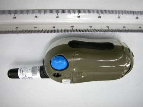
Click to zoom
Application Details
- Equipment Class
- FRF - Part 95 Family Radio Face Held Transmitter
- Date of Grant
- May 04, 2003
- Application Purpose
- Original Equipment
- Date of Application
- May 04, 2003
- Equipment Note
- Transmitter Portion of FRS + GMRS
- Frequency Range
- 467.56250000 - 467.71250000
- Company
- RadioShack Corporation
- Country
- United States
Documents & Files
Document Text
Text extracted from the exhibit documents filed with the FCC. Open a document above to read the original.
Users Manual
21-1902 RadioShack Copyright 22 Ch GMRS/FRS Two-way Radio Your RadioShack 22 Channel FRS/GMRS Two-way Radio provides short-range voice radio communication that lets families and groups keep in touch with each other on specific reserved channels. Your RadioShack 22 Channel FRS/GMRS Two-Way Radio is a lightweight, palm-sized radio you can use to talk with another person who has a FRS/GMRS radio set to the same frequency as your radio. Your radio has 22 channels and 38 different quiet codes, which you can use to talk with another person who has a GMRS or FRS radio set to the same frequency as your radio. Your radio also has auto-squelch, so you will not hear anything on a channel unless someone is transmitting nearby on the same channel. You can connect an optional speaker/microphone and earphone to the radio (neither supplied, available at your local RadioShack store). Your radio’s display has a backlight that turns on for about 5 seconds when you press any key except PTT. Your radio’s other features include: ÿ 22 Channels – provide clear communications for up to two miles in FRS channel and up to three miles in GMRS channel. ÿ Channel Scan – use to find other FRS users. ÿ 38 Quiet Code – eliminates interference from other radios that are not tuned to the same channel and quiet code as your radio. ÿ Key Beep – short beep generation for key pressed acknowledgement except PTT or Function key. ÿ Voice Operated Transmission (VOX) – enables standalone usage and works with handsfree accessory. ÿ Automatic Power Off – the radio auto power off when the radio is idle for 30, 60 or 90 minutes. ÿ Hi/Lo power selection – select the transmit power 0.5W or 1.0W in GMRS channel. ÿ Courtesy Tone – at the end of transmission, it generates for end of message acknowledgement. ÿ Caller ID – In transmitter, user can select the receiver radio to receive the Call. In receiver, the radio will receive the Call that is address to this radio and display the transmitter ID number on LCD. ÿ PLL (Phase –Lock Loop) Controlled Circuitry – provides accurate and stable channel selection. Description of 21-1902 LCD diagram INSTALLING BATTERIES Your radio requires four AAA alkaline batteries (not supplied) or rechargeable nickel-cadmium (Ni-Cd) / nickel-metal hydride (Ni-MH) batteries (supplied) for power. For the best performance and longest life, we recommend RadioShack batteries. Cautions: • Use only fresh batteries of the required size and recommended type. • Do not mix old and new batteries, different types of batteries (alkaline or rechargeable), or rechargeable batteries of different capacities. 1. Rotate VOL/OFF counterclockwise until it clicks to turn off the radio. 2. 3. Pull down the latch on the battery compartment cover, then remove the cover. 4. 5. Slide CHARGE ON/OFF inside the battery compartment to OFF (for alkaline batteries) or ON (for Ni-Cd or Ni-MH rechargeable batteries) when charging the battery through the 6V DC jack on the button of the radio. Warning: Never install non-rechargeable batteries when CHARGE ON/OFF is set to ON. Non-rechargeable batteries can get hot or explode if you try to recharge them. 6. Install four AAA batteries according to the polarity symbols (+ and -) marked inside. 5. Replace the cover and push the latch up until it clicks, then rotate VOL/OFF clockwise until it clicks to turn on the radio. The battery icon’s segments display to show how much power remains. When the Battery bracket flashes, replace alkaline batteries or recharge Ni-Cd or Ni-MH batteries. Warning: • Dispose of old batteries promptly and properly. Do not burn or bury them. Caution: • If you do not plan to use the radio for a month or longer, remove the batteries. Batteries can leak chemicals that can destroy electronic parts. Recharging Ni-Cd or Ni-MH Batteries through 6V DC jack Function CTCSS code Indicator Courtesy Tone 500mW Low Power Battery Level Meter Signal Strength Meter Key Beep Keypad Lock Transmit Voice Operated Transmission Automatic Power Off Channel Indicator Miss ID Indicator Scan Warning: • Do not attempt to charge alkaline batteries. Non-rechargeable batteries can get hot or explode if you try to recharge them. The radio’s DC 6V jack is for charging Ni-Cd or Ni-MH batteries and powering the radio. You can recharge Ni-Cd or Ni-MH batteries inside the radio at home or vehicle, using a 6V, 600mA AC or DC adapter and a size F Adaptaplug TM connector. Cautions: • You must use a Class 2 power source that supplies regulated 6V DC (Not more than 6V) and delivers at least 600mA. Its center tip must be set to positive and its plug must fit the radio’s DC 6V jack. Using an adapter that does not meet these specifications could damage the radio or the adapter. • Always connect the adapter to the radio before you connect it to an external power source (such as an AC outlet or a vehicle cigarette-lighter socket). When you finish, disconnect the adapter from the power source before you disconnect it from the radio. 1. Rotate VOL/OFF fully counterclockwise to turn off the radio. 2. Pull down the latch on the battery compartment cover and remove the cover. 3. Set CHARGE ON/OFF to ON. 4. Place four Ni-Cd or Ni-MH batteries in the compartment according to the polarity symbols (+ and -) marked inside. Then replace the cover and push the latch up until it clicks. 5. Attach the Adaptaplug to the adapter so TIP reads positive (+). 6. Connect the Adaptaplug’s other end to the radio’s DC 6V jack and plug the adapter into a standard AC outlet or vehicle’s power source. Note: • Complete charging takes about 10 hours. When charging is complete, unplug the AC or DC adapter from the power source, then disconnect it from the radio’s DC 6V jack. • Ni-MH batteries take longer to charge than Ni-Cd batteries. Recharging Ni-CD or Ni-MH batteries through slow-charger 1. Power up the slow-charger. 2. Place four Ni-CD or Ni-MH batteries in the compartment according to the polarity symbols (+ and -) marked inside, then replace the co…
Text truncated - open the document above for the full version.
Cover Letter(s)
From: Roland Gubisch ITS/ES-Box Sent: Friday, April 11, 2003 5:53 PM To: Sandy Lee ITS/ES-HKG Cc: Joyce Chan ITS/ES-HKG; Danielle Gravelle ITS/ES-Box; Wilson Loke ITS/ES-HKG Subject: RE: RadioShack FCC ID: AAO2101902 Sandy: The RF output power of this device requires SAR (RF exposure) measurements - which are not provided - to be certified. We note that this radio has a belt clip and may be operated clipped to the belt, using the accessory microphone and earphone. Thus it must meet body-worn SAR limits. The TCB limitation on output power without SAR data is as follows: (1) for portable devices held < 2.5 cm from the body (belt clip position), limit = (60/f, GHz) mW for continuous duty, (120/f, GHz) mW for push-to-talk (2) for portable devices held > 2.5 cm from the body (face-held position), limit = (120/f, GHz) mW for continuous duty, (240/f, GHz) mW for push-to-talk The center frequency of this device is 0.4626375 GHz, so the upper limit of power is 259 mW average for body-worn applications. This exceeds the measured RF power in both FRS and GMRS modes. If SAR data is provided, we can certify push-to-talk devices in this frequency band up to 3.9W. Please note that the FCC would also require SAR data if the application were submitted directly, owing to the body-worn configuration. Regards, Roland -----Original Message----- From: Roland Gubisch ITS/ES-Box Sent: Friday, April 11, 2003 4:01 PM To: Sandy Lee ITS/ES-HKG Cc: Joyce Chan ITS/ES-HKG; Danielle Gravelle ITS/ES-Box Subject: RadioShack FCC ID: AAO2101902 Dear Sandy: Thank you for this application. Technical review has been started. We note the following issue with respect to the User Manual: The requirement for the user to obtain an FCC license prior to using the GMRS frequencies is not prominent in the manual, nor does there appear to be an informational insert (see below) which cautions the user to obtain a license. The Grant of Authorization for this device will contain the following wording: This device is authorized to operate in the following radio services: FRS (Part 95B) or GMRS (Part 95A). There must be an informational insert inside the box (product package) that clearly informs the consumer (buyer/owner) when the radio is transmitting on GMRS frequencies, that operation on GMRS frequencies require an FCC license and such operation is subject to additional rules specified in 47 C.F.R. Part 95. Sample text for an informational insert, as required in the Grant, can follow this example (below) from an FCC-certified GMRS/FRS radio. The insert is printed as a separate card, on bright colored stock: "This [manufacturer's name] radio operates on General Mobile Radio Service (GMRS) frequencies and is subject to the Rules of the Federal Communications Commission (FCC). The FCC requires the issuance of a radio license before operating on GMRS frequencies. "Instructions on applying for the license are included in the User Manual. For more GMRS information, see http://www.fcc.gov/wtb/prs/genmbl.html . "Violations of FCC rules and unlicensed operation on GMRS frequencies may subject the radio operator to serious penalties as provided in Sections 501 and 502 of the Communications Act, as amended. "When operating on channels 1 - 7 or 15 - 22, this radio is using GMRS frequencies. In addition to having a license before using these channels, every GMRS user must cooperate in sharing channels with other GMRS users by monitoring the channel before initiating transmissions, waiting until communications in progress are completed before initiating transmissions except in an emergency, engaging in only permissible communications, limiting transmissions to the minimum practical transmission time, and using the call sign issued by the FCC for station identification." The wording suggested above does not have to be followed exactly. However, a separate insert is required Other suitable notices (recommended, not required) regarding the GMRS capability of the GMRS/FRS radio can appear on the outside of the User Manual, as: "FCC GMRS License required" Please provide an exhibit which complies with the requirement for an informational insert. Technical review will be completed shortly. Regards, Roland
Cover Letter(s)
NATA Accredited Laboratory Number: 5292 EMC Technologies Pty. Ltd., 57 Assembly Dve., Tullamarine, Vic., 3043, Australia. Phone : +61 3 9335 3333 Fax: +61 3 9338 9260 www.emctech.com.au To: Intertek Testing Services NA, Inc. Fax: 978-263-7086 Attention: Roland W. Gubisch Phone: 978-635-8500 From: Aaron Sargent No of pages: 1 Date: 03 May 2003 Subject: Clarification of SAR test data for reports M030324 & M030330 EMC Technologies SAR Test Reports: M030324 (FCC ID: AA02101902) M030330 (FCC ID: AA02101903) Dear Roland Please find our response to your questions listed below: Q1) Table 1 on page 5 of both reports lists "Maximum Conducted Output Power Measured." In clause 2.4 beneath the table is the sentence: "The conducted output power of the device, was not measured due to lack of a suitable antenna port." My question: if conducted output power was not measured, how was it obtained in Table 1 above? A1) On completion of the SAR tests the test samples were modified to accept a standard RF connector at the RF output of the device. Circuit diagrams were supplied by ITS Hong Kong to enable these modifications to be undertaken. The conducted power of the device was subsequently measured with a calibrated Power Meter. Q2) SAR Measurement Results in Table 12, page 16 of both reports, lists the 1g measured SAR at 100% duty cycle (column 6), the extrapolated results for 50% duty cycle and measured drift (column 7), and the measured drift (column 8). I would have expected the mathematics relating columns 6 - 8 to be something like: Column 7 = (Column 6 - column 8)/2 or similar. However, that does not seem to be the case. My question: please explain the mathematical relationship among columns 6, 7 and 8 of the reported SAR data. A2) The relationship is as follows: Column 7 = [Column 6 * InvLog(|Column 8|/10)]/2 The drift is converted to a percentage increase before being multiplied by the corresponding SAR value. The resulting value is then divided by a factor of 2. Kind Regards Aaron Sargent EMR Engineer EMC Technologies Pty Ltd EMC Technologies Pty Ltd ABN 82 057 105 549 57 Assembly Drive Tullamarine Victoria Australia 3043 Ph: + 613 9335 3333 Fax: + 613 9338 9260 email: [email protected]
External Photos
Test Setup FCCID : AAO2101902 External Photo – front External Photo - rear
Internal Photos
Test Setup FCCID : AAO2101902 Internal Photo – 1 Internal Photo - 2 Test Setup FCCID : AAO2101902 Internal Photo – 3 Internal Photo – 4 Test Setup FCCID : AAO2101902 Internal Photo – 5
Operational Description
1 of 3 TRANSCEIVER CIRCUIT DESCRIPTION 21-1902 is a single board design which consists both RF and Baseband part. RF PART The RF part contains all necessary RF circuit. It converts the RF signal picked up by the antenna to demodulated analogue signal for further processing. Besides, the base band analogue signal, including voice and CTCSS tone, will use to FM-modulate the RF carrier during transmission. The main building blocks of the RF part includes a LNA, a SAW filter, a Mixer, a VCO, a Ceramic filter, FM-IF detector circuit and power amplifier for transmission. Among those building blocks, the RF circuit can be divided into two sections. A: RX section This product employs traditional double conversion superheterodyne architecture with the following functional blocks: 1. The LNA with cascade configuration is composed by transistor Q1 and Q2. It has the merits of low noise figure and high insertion gain. 2. The LO signal is generated by VCO which is phase locked with the reference TCXO circuit (X801) at the 10.475MHz. The TCXO can stabilize the frequency of the oscillator within 5ppm from –20 to +50 degree C. The LO signal is amplified by transistor Q4 and coupled to the mixer (Q3) for RF to IF conversion. The LO frequency is controlled by the PLL (U201) after received command from MCU (U101). 3. The first image rejection filter, F1, is a SAW (surface acoustic wave) device, with the merits of having low insertion loss and high stop band attenuation. 4. The mixer is a common emitter configured transistor Q3. It converts RF signal to an IF of 21.4MHz. This IF will further be filtered by the crystal filter F2. 5. Inside the FM-IF chip, the IF signal is further down converted to 450KHz second IF demodulation. The second LO signal is generated by the reference oscillator of the PLL chip. The second IF signal is also further filtered by the ceramic filter for better adjacent channel rejection response. The second IF signal is then demodulated by the resonator X1. The demodulated audio signal will be transferred to the main board for further processing. 6. By trimming the VR1, the audio noise signal level to the internal comparator of the FM IF chip 5019 can be varied. Since the comparator output was used to determine the status of received signal quality, and hence the squelch level can be adjusted. B: TX section 1. The TX carrier is also generated by the VCO with the control from PLL chip. The VCO signal is coupled to amplifier Q501 and Q502. The output signal will be boosted up by the FET power amplifier Q503. 2 of 3 BASE BAND PART The digital part controlled all the base band signal including voltage regulation, battery charging, keyboard input, call tone generator, CTCSS encode/decode, VOX, and LCD display. 1. Voltage regulation: The operating voltage of the circuit is stabilized by the 3.5V voltage regulator U103. 2. Power management: In order to extend the battery life of the unit, unnecessary circuit during different operation modes will be shut down for power saving. The on and off mechanism is controlled by the MCU with the help of some analogue switches which are realized by transistors: They can be classified as : a. Q101 VCO circuit b. Q102 RX RF circuit c. Q103 TX RF circuit d. Q112 MIC circuit 3. Display: The channel number, Quiet code, C-Tone icon, TX icon, Lock icon, battery icon will be prompted to the users by LCD. There is also a backlight LED for better visual effect under dim environment. 4. Keyboard input: The transceiver had several function keys such as MENU(QUIET), UP(SCAN), DOWN(CALL), CALL-ID, PTT and FUNC switch. During the operation, all these function key input will be handled by the MCU. 5. Memory: The memory or setting of the transceiver is stored in the EEPROM U102. 6. Low battery detection: It is realized by the internal A/D of the MCU during power saving mode. 7. High pass filter, Pre-emphasis, Limiter and Low pass filter: The acoustic input transducer by the microphone will go through a 300Hz high pass filter first. This HPF is used to reduced the interference between the user voice and CTCSS tone. This HPF is realized by U701. The pre-emphasis is realized by capacitor C706. After the pre-emphasis stage, limiter and low pass filter are inevitable which are realized by U701. 8. De-emphasis, High pass filter and volume control: The demodulated base band signal from RX section needs to be de-emphasised first. Then the signal will pass through the High pass filter for clear audio signal recovery. This section is realized by U302. This signal will feed to the audio amplifier U401 for power boosting. The volume level is control by the rotary resistor SW109. 9. CTCSS tone generator: Three different signals from MCU were connected to the external resistor network to generate the CTCSS tone. This pure CTCSS tone will add to the VCO for FM modulation. 10. CTCSS tone decode: The demodulated base band signal from RX section will pass through the low pass filter U301. The CTCSS tone received will be transformed to square wave by this filter. This signal will be used for decoding. The MCU will decode this signal by checking its frequency and duty cycle. 11. MCU internal clock and reset: The reset is realized by Q104. Since the CTCSS tone is reference with the internal clock of the MCU, 4 MHz ceramic resonator is used as the main resonating element in order to have a better accuracy. 3 of 3 12. Battery charging: This transceiver can use with 6V DC regulated external CLA adaptor. The transceiver can function normally during charging the rechargeable battery in the compartment. 13. Automatic Squelch: The squelch detection signal from RX section will alert the MCU to mute the speaker. The squelch level is controlled by VR1 on the RF part. 14. VOX circuit: The MIC signal is amplified and rectified by amplifier Q701 and coupled to MCU for level detection.
Parts List/Tune Up Info
21-1902 Part List Part NumberDescriptionUsage 7202180320APCB 212 7CBNAK100J*CERAMIC CAPACI 0603 100J5010 C 008 C 015 C 211 C 040 C 508 7CBNAK101J*CERAMIC CAPACI 1608 CH 50V 101J8 C 002 C 205 C 221 C 222 7CBNAK101J*CERAMIC CAPACI 1608 CH 50V 101J6 C 223 C 516 C 731 7CBNAK120J*CERAMIC CAPACI 0603 120J504 C 010 C 501 7CBNAK121J*CERAMIC CAPACI 0603 121J504 C 705 C 709 7CBNAK150J*CERAMIC CAPACI 0603 150J504 CBNAK150JH CERAMIC CAPACITOR 0603 150J50 C 013 C 515 7CBNAK180J*CERAMIC CAPACI 1608 CH 50V 180J6 C 509 C 021 C 118 7CBNAK1R0C*CERAMIC CAPACI 0603 1R0C502 C 026 7CBNAK1R5CMCERAMIC CAPACI GRM39COG1R5C502 C 206 7CBNAK220J*CERAMIC CAPACI 1608 CH 50V 220J2 C 019 7CBNAK221J*CERAMIC CAPACI 1608 CH 50V 221J8 CBNAK221JM CERAMIC CAPACITOR GRM39 COG221JM C 217 C 503 C 507 C 714 7CBNAK270J*CERAMIC CAPACI 0603 270J502 CBNAK270JM CERAMIC CAPACITOR 0603 270J50 C 128 7CBNAK2R0C*CERAMIC CAPACI 1608 CH 50V 2R0C2 C 215 7CBNAK2R0C*CERAMIC CAPACI 1608 CH 50V 2R0C6 C 213 C 006 C 009 7CBNAK330J*CERAMIC CAPACI 1608 CH 50V 330J2 C 031 7CBNAK3R0C*CERAMIC CAPACI 0603 3R0C508 C 005 C 027 C 016 C 207 7CBNAK470J*CERAMIC CAPACI 1608 CH 50V 470J2 C 138 7CBNAK471J*CERAMIC CAPACI 0603 471J508 C 209 C 212 C 214 C 216 7CBNAK471J*CERAMIC CAPACI 0603 471J504 C 220 C 104 7CBNAK4R0C*CERAMIC CAPACI 1608 CH 50V 4R0C6 C 218 C 219 C 204 7CBNAK4R0C*CERAMIC CAPACI 1608 CH 50V 4R0C4 C 522 C 523 7CBNAK680J*CERAMIC CAPACI 1608 CH 50V 680J4 C 408 C 702 7CBNAK6R0C*CERAMIC CAPACI 0603 6R0C502 C 210 7CBNAK7R0C*CERAMIC CAPACI 0603 7R0C502 C 520 7CBNAK820J*CERAMIC CAPACI 1608 CH 50V 820J2 C 707 7CBNAK8R0D*CERAMIC CAPACI 0603 50V 8pFD4 C 007 C 505 7CJNED105K*CERAMIC CAPACI 0603 X7R105K6.32 C 312 7CJNEE224K*CERAMIC CAPACI 0603X7R 224K106 C 311 C 305 C 406 7CJNEE474K*CERAMIC CAPACI 0603X7R474K102 C 201 7CJVPE475Z*CERAMIC CAPACI 0805 Y5V 475Z102 C 124 7CJNEG473K*CERAMIC CAPACI 0603 X7R 473K162 C 130 7CJNEK102K*CERAMIC CAPACI 0603 X7R 102K508 C 014 C 018 C 024 C 025 7CJNEK102K*CERAMIC CAPACI 0603 X7R 102K508 C 030 C 011 C 086 C 012 7CJNEK102K*CERAMIC CAPACI 0603 X7R 102K508 C 502 C 506 C 513 C 517 7CJNEK102K*CERAMIC CAPACI 0603 X7R 102K508 C 518 C 402 C 704 C 720 7CJNEK102K*CERAMIC CAPACI 0603 X7R 102K504 C 115 C 119 7CJNEK103K*CERAMIC CAPACI 0603 X7R 103K506 C 022 C 112 C 317 7CJNEK103K*CERAMIC CAPACI 0603 X7R 103K508 C 113 C 121 C 125 C 171 7CJNEK103K*CERAMIC CAPACI 0603 X7R 103K508 C 172 C 203 C 224 C 306 7CJNEK103K*CERAMIC CAPACI 0603 X7R 103K506 C 314 C 320 C 504 7CJNEK103K*CERAMIC CAPACI 0603 X7R 103K508 C 711 C 722 C 723 C 703 7CJNEK123K*CERAMIC CAPACI 0603 X7R 123K504 C 315 C 321 7CJNEK222K*CERAMIC CAPACI 0603 X7R 222K502 C 309 7CJNEK223K*CERAMIC CAPACI 0603 X7R 223K508 C 701 C 724 C 727 C 401 7CJNAD225KMCERAMIC CAPACI GRM188R60J225KE01D2 CJNAD225KH CERAMIC CAPACITOR 0603 225K6.3 C 202 7CJNEK272K*CERAMIC CAPACI 0603 X7R 272K504 C 319 C 725 7CJNEK332K*CERAMIC CAPACI 0603 X7R 332K504 C 318 C 726 7CJNEK333K*CERAMIC CAPACI 0603 X7R 333K506 C 035 C 145 C 304 7CJNEK472K*CERAMIC CAPACI 0603 X7R 472K504 C 032 C 131 7CJNEK562K*CERAMIC CAPACI 0603 X7R 562K502 C 706 7CJNEK822K*CERAMIC CAPACI 0603 X7R 822K502 C 308 7CJNPG104Z*CERAMIC CAPACI 0603 Y5V 104Z168 C 020 C 037 C 038 C 047 7CJNPG104Z*CERAMIC CAPACI 0603 Y5V 104Z168 C 101 C 108 C 117 C 322 7CJNPG104Z*CERAMIC CAPACI 0603 Y5V 104Z168 C 323 C 403 C 404 C 409 7CJNPG104Z*CERAMIC CAPACI 0603 Y5V 104Z168 C 708 C 710 C 713 C 712 7CJNPG104Z*CERAMIC CAPACI 0603 Y5V 104Z164 C 717 C 719 7CJNPG104Z*CERAMIC CAPACI 0603 Y5V 104Z164 C 029 C 033 7CJNPG105Z*CERAMIC CAPACI 0603 Y5V 105Z168 C 034 C 067 C 103 C 122 7CJNPG105Z*CERAMIC CAPACI 0603 Y5V 105Z168 C 111 C 301 C 302 C 303 7CJNPG105Z*CERAMIC CAPACI 0603 Y5V 105Z168 C 310 C 313 C 316 C 715 7CJNPG105Z*CERAMIC CAPACI 0603 Y5V 105Z168 C 718 C 728 C 729 C 407 7CJNPG105Z*CERAMIC CAPACI 0603 Y5V 105Z166 C 001 C 003 C 004 7CJNPG154Z*CERAMIC CAPACI 0603 Y5V 154Z162 C 107 7CJVPE475Z*CERAMIC CAPACI 0805 Y5V 475Z106 CJVPE475ZM CERAMIC CAPACITOR 0805 Y5V 475Z10 C 039 C 226 C 511 7CJVPE475Z*CERAMIC CAPACI 0805 Y5V 475Z104 CJVPE475ZM CERAMIC CAPACITOR 0805 Y5V 475Z10 C 716 C 721 7CJWPE106Z*CERAMIC CAPACI 1206 Y5V 106Z102 CJWPE106ZM CERAMIC CAPACITOR 1206 Y5V 106Z10 C 110 7RG0SN100J*M-GLAZE RESIST RK 1/16C 10 ohmJ2 R 506 7RG0SN000J*M-GLAZE RESIST RK 1/16C 000 ohmJ12 R 016 R 026 R 041 R 510 R 017 R018 7RG0SN100J*M-GLAZE RESIST RK 1/16C 10 ohmJ8 R 008 R 144 R 150 R 110 7RG0SN101J*M-GLAZE RESIST RK1/16C 100 ohmJ6 R 013 R 213 R 215 7RG0SN101J*M-GLAZE RESIST RK1/16C 100 ohmJ8 R 211 R 222 R 503 R 157 7RG0SN101J*M-GLAZE RESIST RK1/16C 100 ohmJ4 R 135 R 139 7RG0SN101J*M-GLAZE RESIST RK1/16C 100 ohmJ6 R 019 R 027 R 028 7RG0SN102J*M-GLAZE RESIST RK1/16C 1 KohmJ8 R 004 R 007 R 216 R 217 7RG0SN102J*M-GLAZE RESIST RK1/16C 1 KohmJ8 R 218 R 219 R 501 R 504 7RG0SN102J*M-GLAZE RESIST RK1/16C 1 KohmJ8 R 508 R 509 R 701 R 712 7RG0SN102J*M-GLAZE RESIST RK1/16C 1 KohmJ6 R 724 R 410 R 108 7RG0SN103J*M-GLAZE RESIST RK1/16C 10 KohmJ8 R 204 R 205 R 105 R 153 7RG0SN103J*M-GLAZE RESIST RK1/16C 10 KohmJ6 R 316 R 405 R 704 7RG0SN103J*M-GLAZE RESIST RK1/16C 10 KohmJ6 R 728 R 732 R 736 7RG0SN104J*M-GLAZE RESIST RK1/16C 100 KohmJ6 R 148 R 409 R 173 7RG0SN104J*M-GLAZE RESIST RK1/16C 100 KohmJ6 R 713 R 718 R 714 7RG0SN104J*M-GLAZE RESIST RK1/16C 100 KohmJ8 R 723 R 730 R 109 R 421 7RG0SN105J*M-GLAZE RESIST RK1/16C 1 MohmJ8 R 023 R 130 R 311 R 703 7RG0SN122J*M-GLAZE RESIST RK1/16C 1R2 KohmJ2 R 012 7RG0SN123J*M-GLAZE RESIST RK 1/16C 12KOHMJ2 R 305 7RG0SN473J*M-GLAZE RESIST RK1/16C 47 KohmJ2 R 715 7RG0SN153J*M-GLAZE RESIST RK 1/16C 15KohmJ2 R 502 7RG0SN154J*M-GLAZE RESIST RK 1/16C 150KohmJ2 R 511 7RG0SN182J*M-GLAZE RESIST RK1/16C 1R8 KohmJ4 R 212 R 717 7RG0SN201J*M-GLAZE RESIST RK 1/16C 200OHMJ2 R 009 7RG0SN204J*M-GLAZE RESIST RK 1/16C 200KohmJ4 R 317 R 706 7RG0SN205J*M-GLAZE RESIST RK 1/16C 2R0MohmJ2 R 140 7RG0SN220J*M-GLAZE RESIST RK 1/16C 22 ohmJ2 R 411 7RG0SN221J*M-GLAZE RESIST RK1/16C 220 ohmJ8 R 002 R 011 R 015 R 022 7RG0SN222J*M-GLAZE RESIST RK1/16C 2R2 KohmJ8 R 003 R 207 R 209 R 106 7RG0SN222J*M-GLAZE R…
Text truncated - open the document above for the full version.
Parts List/Tune Up Info
Tandy Electronics (China) Limited TEL: (0752)2261383 FAX : (0752)2261798 21-1902 Alignment Procedures March 20 th , 2003 Page 1 of 2 Approval by Check by Bunny NG Revision B Total pages 2 Standard Alignment Conditions: Power Supply: 6 V DC Antenna Impedance: 50 ohm RF Signal Modulation: FM, 1 kHz sine wave with 3 kHz deviation Tuning Channel: Channel 1 (462.5625MHz) Audio Loading: 32 ohm (BTL) Audio Output Power: 50 mW 1. VCO Tuning The tunable range of the VCO should be adjusted to make sure the control voltage of the VCO is enough margin for PLL locking 1.1 Tuning component : L201 1.2 Equipment : DVM for voltage measurement 1.3 Personnel : Skilful 1.4 Measure the control voltage of VCO to make sure there is enough margin for PLL margin: 1.4.1 Set to channel 1 1.4.2 Measure the voltage at TP201 and it should be higher than 0.8V 1.4.3 Set to channel 14 1.4.4 Press PTT key 1.4.5 Measure the voltage at TP201 and it should be lower than 2.3V 2. Tx Frequency Tuning The reference frequency 10.475MHz of the PLL is generated by the TCXO circuit (X801 and Q801). Since the TCXO frequency and Tx output frequency are the fix multiple relationship through program controlled, we can measure the Tx output signal frequency to check the accuracy of TCXO output frequency. 2.1 Tuning component : VC801 2.2 Equipment : Spectrum analyzer with high stability time base 2.3 Personnel : Skilful 2.4 Measure the Tx output signal frequency to make sure it is accuracy: 2.4.1 Set channel 1. 2.4.2 Press PTT 2.4.3 Monitor the frequency of the Tx output signal through a coaxial cable at the antenna terminator. 2.4.4 Tune the VC801 until the Tx frequency is at 462. 5625MHz ± 0.5 kHz 3. Modulation Limit Tuning Set the transceiver to operate in Channel 1 and set the CTCSS tone to38, and connect the antenna output of the transceiver to the RF tester and monitor the modulation level. Input audio signal ( 1 kHz sine wave, 100 mV ) through the stereo jack to the transceiver. RF signal is transmitted. Adjust VR701 until the frequency deviation is around but less than 2.3 kHz Tandy Electronics (China) Limited TEL: (0752)2261383 FAX : (0752)2261798 21-1902 Alignment Procedures March 20 th , 2003 Page 2 of 2 3.1 Tuning component : VR701 3.2 Equipment : Through stereo jack cable, connect the audio generator and transceiver together. Communication test set and modulation analyzer. 3.3 Personnel : Skilful 4. Squelch Tuning The squelch function of 21-1902 is realized by rectifying the demodulated noise signal. If the rectified noise level is higher than the threshold. A logic level will be generated to the MCU to determine the on and off of speaker. Hence by adjusting the level input to the rectifier, the squelch level can be controlled. 4.1 Tuning component : VR1 4.2 Equipment : Test jig with pin connected to speaker terminal Signal generator at –123dBm with 1KHz modulation source of 1.5KHz FM modulation 4.3 Personnel : Skiful 4.4 Testing procedure : 4.4.1 Input RF signal = 462.5625 MHz, frequency deviation = 1.5 kHz, modulating signal = 1 kHz. 4.4.2 Connect the transceiver to the RF generator and monitor the audio output from the speaker terminal. 4.4.3 Rotate VR1 until the audio signal is ON. 4.4.4 Adjust output power of the RF generator until the SINAD meter show 10-13dB. 4.4.5 Rotate VR1 until the audio signal is JUST muted. 4.4.6 Increase the output power in ½ dB step until the audio is just resumed. The SINAD meter should read 12-15 dB. 5. RF power Tuning The ERP power should be tuned to 920mW in GMRS channel (channel 1-7, 15-22) The ERP power should be tuned to 470mW in FRS channel (channel 8-14) 4.1 Tuning component : VR501 4.2 Equipment : Communication test set with RF power measurement option 4.3 Personnel : Skiful 4.4 Testing procedure : 4.4.1 Connect the DUT to the communication test set. 4.4.2 Set to channel 14. 4.4.3 Press PTT key to activate the TX ON. 4.4.4 Adjust VR501 to 500mW. 4.4.5 Set to channel 1. 4.4.6 Press PTT key, RF power is around 1000mW.
RF Exposure Info
FCC ID: AAO2101902 EMC Technologies Report No. M030324 Page 1 of 39 This document shall not be copied or reproduced, except in full without the written permission of the Technical Director , EMC Technologies Pty. Ltd. www. emctech.com.au SAR Test Report Report Number: M030324 Test Sample: Handheld Transceiver Model Number: 21-1902 Tested For: RadioShack Corporation FCC ID: AA02101902 Date of Issue: 11 th April 2003 EMC Technologies Pty Ltd reports apply only to the specific samples tested under stated test conditions. It is the manufacturer’s responsibility to assure that additional production units of this model are manufactured with identical electrical and mechanical components. EMC Technologies Pty Ltd shall have no liability for any deductions, inferences or generalisations drawn by the client or others from EMC Technologies Pty Ltd issued reports. This report shall not be used to claim, constitute or imply product endorsement by EMC Technologies Pty Ltd. EMC Technologies Pty Ltd A.C.N. 057 105 549 57 Assembly Drive Tullamarine Victoria Australia 3043 Ph: + 613 9335 3333 Fax: + 613 9338 9260 email: [email protected] FCC ID: AAO2101902 EMC Technologies Report No. M030324 2 of 39 This document shall not be copied or reproduced, except in full without the written permission of the Technical Director , EMC Technologies Pty. Ltd. www. emctech.com.au CONTENTS 1.0 GENERAL INFORMATION ....................................…
Text truncated - open the document above for the full version.
Contact Information
Applicant
Elizabeth Granados(Regulatory Affairs Manager)
Technical Contact
Intertek Testing Services Hong Kong Ltd.Derek Leung
[email protected]852-2173-8504
2.F., Garment Centre, · Kowloon · Hong Kong
Non-Technical Contact
Intertek Testing Services Hong Kong Ltd.Derek Leung
[email protected]852-2173-8504
Test Firm
Intertek Testing Services Hong KongBilly Chow
Technical Specifications
| # | Rule Parts | Frequency Range | Power Output | Emission | Tolerance |
|---|---|---|---|---|---|
| 2 | 95B | 467.5625 MHz - 467.7125 MHz | 470.00 mW | 10K1F3E | 2.5 ppm |
Other Applications from RadioShack Corporation

AAO2302500
Feb 10, 2015Bluetooth Power Bank
Equipment Class
DXX - Part 15 Low Power Communication Device Transmitter
AAO4300124C
May 02, 2013900MHz Wireless Intercom
Equipment Class
DXT - Part 15 Low Power Transceiver, Rx Verified
AAO1200876
Nov 30, 2011Universal FM Transmitter
Equipment Class
DXX - Part 15 Low Power Communication Device Transmitter
AAO1200962
Aug 02, 2011Universal FM Transmitter
Equipment Class
DXX - Part 15 Low Power Communication Device Transmitter
AAO1500044T
Apr 02, 20112.4GHz Digital Wireless Rear Speaker Kit - Transmitter
Equipment Class
DSS - Part 15 Spread Spectrum Transmitter