AAO3201258RReceiver for Wireless Microphone
RadioShack Corporation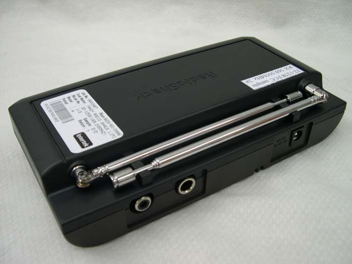
Click to zoom
Application Details
- Equipment Class
- CXX - Communications Rcvr for use w/ licensed Tx and CBs
- Date of Grant
- Mar 21, 2006
- Application Purpose
- Original Equipment
- Date of Application
- Mar 21, 2006
- Equipment Note
- Receiver for Wireless Microphone
- Frequency Range
- 171.90500000 - 171.90500000
- Company
- RadioShack Corporation
- Country
- United States
Documents & Files
Document Text
Text extracted from the exhibit documents filed with the FCC. Open a document above to read the original.
Users Manual
installing batteries for the microphone 1. Unscrew the microphone grille to loosen it and remove the battery cover. 2. Insert two AA batteries. 3. Replace the battery cover and screw the microphone grille when completed. battery notes • When the indicator on the microphone becomes dim, replace the batteries. • Dispose of old batteries promptly and properly. • Do not burn or bury batteries. • Use only fresh batteries of the required size and recommended type. • Do not mix batteries of different sizes or types. • If you do not plan to use your microphone system for a month or more, remove the batteries. Batteries can leak chemicals that can damage electronic parts. Thank you for purchasing your 170MHz Single Channel Wireless Microphone System from RadioShack. Your system will transmit microphone signals while you move freely up to 200 feet away from the receiver. microphone receiver 9V AC adapter user’s guide what’s included powering the microphone system 32-1258 170MHz Single Channel Wireless Microphone System 1. Press POWER on the receiver to turn it on. The POWER indicator will light up. 2. Fully extend the receiver’s antenna. 3. Turn on your ��� ��������r�� ���� ����� ����r or o���r�u��o �y����.��� ����r �o�u���o �o��r��������.��� ��������r�� ���� ����� ����r or o���r �u��o �y����.��� ����r �o�u���o �o��r��������.. ��� ����r �o�u�� �o �o��r��� �����. 4. ��� ��� ���ro��on�’� OFF/MUTE/TALK switch to TALK. The READY indicator will light up. 5. ������ �� � nor��� ����� �n� ��ju�� VOLUME on the receiver. 6. If you w�n� �o �o��n��r��y �urn off ��� ���ro��on��� ��� ��� OFF/MUTE/TALK to MUTE. Use MUTE to avoid the popping noise that might occur if you turn OFF/MUTE/TALK to OFF �n� ���n b���� �o TALK. 7. Rotate SQUELCH to control the transmitting distance. Turn to minimum to increase the transmitting distance. When you finish using the system, be sure to turn the OFF/MUTE/TALK switchon the microphone to OFF mode to save battery power. using the microphone system Frequency ........................................................................................ .................169.505MHz�� 170.245MHz or 171.905MHzTr�n������r: RF Power ...............................................................................10dBm ��n�������y ..................................................106 �B ��L �� 7KHz FM Operating Range ..................................................200 feet (Typical) �ow�r �our�� (���ro��on�) ...............................Two AA Batteries Receiver ��n�������y w��� �/N 20�B ..........................................................1uV �/N r���o �� 1�V RF �n�u� .......................................................75dB I��g� R�j����on .......................................................................55dB L�n� Ou��u� ...........................................................................510mV Microphone Output ................................................................10mV Frequency Response ................................................120---13000Hz Power Requirement ............................AC-DC adapter 9V@250mA NOTE: Specifications are typical; individual units may vary. Specifications are subject to change and improvement without notice. specifications Warning: Modifying, tampering with, or adjusting this unit, or replacing any transmitter component (crystal, semiconductor, etc.) may result in a violation of the FCC rules. This equipment has been tested and found to comply with the limits for a Class B digital device, pursuant to Part 15 of the FCC Rules. These limits are designed to provide reasonable protection against harmful interference in a residential installation. This equipment generates, uses, and can radiate radio frequency energy and, if not installed and used in accordance with the instructions, may cause harmful interference to radio communications. However, there is no guarantee that interference will not occur in a particular installation. If this equipment does cause harmful interference to radio or television reception, which can be determined by turning the equipment off and on, the user is encouraged to try to correct the interference by one or more of the following measures: • Reorient or relocate the receiving antenna. • Increase the separation between the equipment and receiver. • Connect the equipment into an outlet on a circuit different from that to which the receiver is connected. Consult your local RadioShack store or an experienced radio/TV technician for help. If you cannot eliminate the interference, the FCC requires that you stop using your microphone system. Changes or modifications not expressly approved by RadioShack may cause interference and void the user’s authority to operate the equipment. This device complies with Part 15 of the FCC Rules. Operation is subject to the condition that this device may not cause harmful interference. This wireless microphone system complies with Part 90 of the FCC Rules. There are three frequencies available for the system. You must obtain a license for each frequency you plan to use before operating your system. One license can include both frequencies. Visit http://wireless.fcc.gov/uls/, or call your local FCC office to apply for your license. Your ability to obtain a license will depend on how you plan to use the system. For RF exposure “IMPORTANT NOTE: To comply with the FCC RF exposure compliance requirements, no change to the antenna or the device is permitted. Any change to the antenna or the device could result in the system exceeding the RF exposure requirements.” For devices less than 200mW ERP SAFETY INFORMATION Your wireless microphone contains a low power transmitter. When the EUT is powered on, it sends out radio frequency (RF) signals. In August 1996, the Federal Communications Commissions (FCC) adopted RF exposure guidelines with safety levels for wireless devices. IMPORTANT To maintain compliance with the FCC’s RF exposure guidelines, hold the transmitter and antenna at …
Text truncated - open the document above for the full version.
External Photos
INTERTEK TESTING SERVICE Report No.: 0602987 FCC ID: AAO3201258R Equipment Photographs Model : 32-1258 (External) INTERTEK TESTING SERVICE Report No.: 0602987 FCC ID: AAO3201258R Equipment Photographs Model : 32-1258 (External) INTERTEK TESTING SERVICE Report No.: 0602987 FCC ID: AAO3201258R Equipment Photographs Model : 32-1258 (External)
ID Label/Location Info
Rating label (Engraving) 32-1258 RX label and location 03A06 TEC Q.C. Q.C Label Bottom cabinet Frequency label (1,2,3) 169.505 MHz Custom Manufactured in China for RadioShack Corporation, Ft. Worth, TX 76102 Cat. No. 32-1258 This device complies with Part 15 of the FCC Rules. Operation is subject to the condition that this device may not cause harmful interference. FCC ID: AAO3201258R
Internal Photos
INTERTEK TESTING SERVICE Report No.: 0602987 FCC ID: AAO3201258R Equipment Photographs Model : 32-1258 (Internal) INTERTEK TESTING SERVICE Report No.: 0602987 FCC ID: AAO3201258R Equipment Photographs Model : 32-1258 (Internal) INTERTEK TESTING SERVICE Report No.: 0602987 FCC ID: AAO3201258R Equipment Photographs Model : 32-1258 (Internal) INTERTEK TESTING SERVICE Report No.: 0602987 FCC ID: AAO3201258R Equipment Photographs Model : 32-1258 (Internal) INTERTEK TESTING SERVICE Report No.: 0602987 FCC ID: AAO3201258R Equipment Photographs Model : 32-1258 (Internal) INTERTEK TESTING SERVICE Report No.: 0602987 FCC ID: AAO3201258R Equipment Photographs Model : 32-1258 (Internal) INTERTEK TESTING SERVICE Report No.: 0602987 FCC ID: AAO3201258R Equipment Photographs Model : 32-1258 (Internal)
Operational Description
Circuit Description Theory of Operations Circuit Description Receiver(RX): 1. RF and Demodulation Low Noise Amplifier(LNA) consist of the Q1 and Q2, FIL1 for suppression the image frequency. Crystal X1 (three frequencies: 52.935MHz/53.1817MHz/53.735MHz) VC1 and Q5 etc. act oscillator, the Lo signal (triple up to the desired LO frequency 158.805MHz/159.545MHz/161.205MHz) will be selected by L9 C40 L8 C36. RF signal from LNA and Lo signal is mixed by Q3, FIL2 Q4 FIL3 act the IF amplifier and filter the unwanted signal .U1(TA31161) is RF demodulation IC, AF and RSSI signal will be output . 2. Power control regulator S1 is Power ON/OFF push switch, Q9 Q7 Q8 and C44 reduce the “POP” noise, Q13 ZD1 and C69 provide +8v DC power and U3 provides a +5v DC for circuit, the POWER LED D2 will light when the S1 sets to ON. 3. Mute and Squelch The Mute circuit are controlled by U2-B VR2 and Q15, if the RF signal is weak then the Q15 will short the AF signal to ground. The noise section from the RF MODULE will be selected by U2-A U2-B and amplified by Q12 and rectifing the DC voltage which is filtered by C56 and R47 compare with the voltage of the U2’s Pin 9 from SQUELCH control VR1 and VR5, if the RF signal is weak then the AF signal will be shorted by Q6 and Q16 to ground and the indicator SQ-LED D4 will OFF. 4. AF Amplifier and Expander Q14 and Q10 etc. are the AF amplifier,U4 acts the expander to improve the SNR of the recover voice. VR3 is volume control and J2 and J3 are different AF out (Line output or Mic output). FCC ID: AAO3201258R
Test Report
• The test results reported in this test report shall refer only to the sample actually tested and shall not refer or be deemed to refer to bulk from which such a sample may be said to have been obtained. • This report shall not be reproduced except in full without prior authorization from Intertek Testing Services Hong Kong Limited • For Terms And Conditions of the services, it can be provided upon request. • The evaluation data of the report will be kept for 3 years from the date of issuance. Intertek Testing Services Hong Kong Ltd. 2/F., Garment Centre, 576 Castle Peak Road, Kowloon, Hong Kong. Tel: (852) 2173 8888 Fax: (852) 2785 5487 Website: www.hk.intertek-etlsemko.com RadioShack Corporation Application For Certification (FCC ID: AAO3201258R) Superheterodyne Receiver 0602987 TC/el March 22, 2006 INTERTEK TESTING SERVICES FCC ID: AAO3201258R i LIST OF EXHIBITS INTRODUCTION EXHIBIT 1: General Description EXHIBIT 2: System Test Configuration EXHIBIT 3: Emission Results EXHIBIT 4: Equipment Photographs EXHIBIT 5: Product Labelling EXHIBIT 6: Technical Specifications EXHIBIT 7: Instruction Manual EXHIBIT 8: Miscellaneous Information INTERTEK TESTING SERVICES FCC ID: AAO3201258R ii MEASUREMENT / TECHNICAL REPORT RadioShack Corporation − MODEL: 32-1258 FCC ID: AAO3201258R March 22, 2006 This report concerns (check one:) Original Grant X Class II Change Equipment Type: Superheterodyne Receiver (example: computer, printer, modem, etc.) Deferred grant requested per 47 CFR 0.457(d)(1)(ii)? Yes No X If yes, defer until: date Company Name agrees to notify the Commission by: date of the intended date of announcement of the product so that the grant can be issued on that date. Transition Rules Request per 15.37? Yes No X If no, assumed Part 15, Subpart B for unintentional radiator − the new 47 CFR [10-01-04 Edition] provision. Report prepared by: Alfred Lo Intertek Testing Services 2/F., Garment Center, 576 Castle Peak Road, Kowloon, Hong Kong. Phone: 852-2173-8545 Fax: 852-2371-0914 INTERTEK TESTING SERVICES FCC ID: AAO3201258R iii Table of Contents 1.0 General Description.............................................................................................. 2 1.1 Product Description........................................................................................ 2 1.2 Related Submittal(s) Grants ........................................................................... 2 1.3 Test Methodology........................................................................................... 3 1.4 Test Facility .................................................................................................... 3 2.0 System Test Configuration.................................................................................. 5 2.1 Justification .................................................................................................... 5 2.2 EUT Exercising Software ............................................................................... 5 2.3 Special Accessories ....................................................................................... 5 2.4 Equipment Modification.................................................................................. 6 2.5 Measurement Uncertainty .............................................................................. 6 2.6 Support Equipment List and Description ........................................................ 6 3.0 Emission Results.................................................................................................. 8 3.1 Field Strength Calculation .............................................................................. 9 3.2 Radiated Emission Configuration Photograph ............................................. 11 3.3 Radiated Emission Data............................................................................... 12 3.4 Conducted Emission Configuration Photograph........................................... 15 3.5 Conducted Emission Data............................................................................ 16 4.0 Equipment Photographs.................................................................................... 18 5.0 Product Labelling............................................................................................... 20 6.0 Technical Specifications.................................................................................... 22 7.0 Instruction Manual.............................................................................................. 24 8.0 Miscellaneous Information................................................................................ 26 8.1 Discussion of Pulse Desensitization............................................................. 27 8.2 Calculation of Average Factor ...................................................................... 28 8.3 Emissions Test Procedures ......................................................................... 29 INTERTEK TESTING SERVICES FCC ID: AAO3201258R iv List of attached file Exhibit Type File Description Filename Test Report Test Report report.pdf Operation Description Technical Description descri.pdf Test Setup Photo Radiated Emission radiated photos.pdf Test Setup Photo Conducted Emission conducted photos.pdf Test Report Conducted Emission Test Result conducted.pdf External Photo External Photo external photos.pdf Internal Photo Internal Photo internal photos.pdf Block Diagram Block Diagram block.pdf Schematics Circuit Diagram circuit.pdf ID Label / Location Label Artwork and Location label.pdf User Manual User Manual manual.pdf INTERTEK TESTING SERVICES FCC ID: AAO3201258R 1 EXHIBIT 1 GENERAL DESCRIPTION INTERTEK TESTING SERVICES FCC ID: AAO3201258R 2 1.0 General Description 1.1 Product Description The Equipment Under Test (EUT) is an audio receiver for its corresponding wireless microphone. The main function of the EUT is used to receive the modulated signal that can be transmitting by its corresponding…
Text truncated - open the document above for the full version.
Test Report
Report No.: 0602987 Receiving mode (169.505MHz) AC Mains Ctrl No.: PAGE 1 Tested By:Hong, Report No.:0602987 Scan Settings (1 Range) |--------- Frequencies -----------||----------- Receiver Settings ------------| Start Stop Step IF BW Detector M-Time Atten Preamp OpRge 150k 30M 5k 10k PK+AV 10ms AUTO LN OFF 60dB Final Measurement: x QP / + AV Meas Time: 1 s Subranges: 16 Acc Margin: 20dB Transducer No. Start Stop Name 1 15 9k 30M EW0090 21 9k 30M EW0698 0 10 20 30 40 50 60 70 80 90 dBuV 100 0.15 MHz 30110 F15Q F15A NA Report No.: 0602987 Receiving mode (169.505MHz) AC Mains Ctrl No.: NA Tested By:Hong, Report No.:0602987 Scan Settings (1 Range) |--------- Frequencies -----------||----------- Receiver Settings ------------| Start Stop Step IF BW Detector M-Time Atten Preamp OpRge 150k 30M 5k 10k PK+AV 10ms AUTO LN OFF 60dB Final Measurement Results: no Results Report No.: 0602987 Receiving mode (171.905MHz) AC Mains Ctrl No.: PAGE 1 Tested By:Hong, Report No.:0602987 Scan Settings (1 Range) |--------- Frequencies -----------||----------- Receiver Settings ------------| Start Stop Step IF BW Detector M-Time Atten Preamp OpRge 150k 30M 5k 10k PK+AV 10ms AUTO LN OFF 60dB Final Measurement: x QP / + AV Meas Time: 1 s Subranges: 16 Acc Margin: 20dB Transducer No. Start Stop Name 1 15 9k 30M EW0090 21 9k 30M EW0698 0 10 20 30 40 50 60 70 80 90 dBuV 100 0.15 MHz 30110 F15Q F15A NA Report No.: 0602987 Receiving mode (171.905MHz) AC Mains Ctrl No.: NA Tested By:Hong, Report No.:0602987 Scan Settings (1 Range) |--------- Frequencies -----------||----------- Receiver Settings ------------| Start Stop Step IF BW Detector M-Time Atten Preamp OpRge 150k 30M 5k 10k PK+AV 10ms AUTO LN OFF 60dB Final Measurement Results: no Results
Test Setup Photos
INTERTEK TESTING SERVICE Report No: 0602987 Configuration Photographs Worst-Case Radiated Emissions (Front View) Model : 32-1258 Fig.1 FCC ID: AAO3201258R INTERTEK TESTING SERVICE Report No: 0602987 Configuration Photographs Worst-Case Radiated Emissions (Back View) Model : 32-1258 Fig.2 FCC ID: AAO3201258R
Test Setup Photos
INTERTEK TESTING SERVICE Report No: 0602987 FCC ID: AAO3201258R i Configuration Photographs Worst-Case Line-Conducted Emissions (Front View) Model : 32-1258 INTERTEK TESTING SERVICE Report No: 0602987 FCC ID: AAO3201258R ii Configuration Photographs Worst-Case Line-Conducted Emissions (Back View) Model : 32-1258 INTERTEK TESTING SERVICE Report No: 0602987 FCC ID: AAO3201258R iii Configuration Photographs Worst-Case Line-Conducted Emissions (Side View) Model : 32-1258
Contact Information
Applicant
Elizabeth Granados(Regulatory Affairs Manager)
Technical Contact
Intertek Testing Services Hong Kong LtdAlfred Lo
[email protected]852-21738888
2/F Garment Centre, · Hong Kong · Hong Kong
Non-Technical Contact
Intertek Testing Services Hong Kong LtdAlfred Lo
[email protected]852-21738888
Test Firm
Intertek Testing Services Hong KongBilly Chow
Technical Specifications
| # | Rule Parts | Frequency Range | Power Output |
|---|---|---|---|
| 3 | 15B | 171.905 MHz - 171.905 MHz | - |
Other Applications from RadioShack Corporation

AAO2302500
Feb 10, 2015Bluetooth Power Bank
Equipment Class
DXX - Part 15 Low Power Communication Device Transmitter
AAO4300124C
May 02, 2013900MHz Wireless Intercom
Equipment Class
DXT - Part 15 Low Power Transceiver, Rx Verified
AAO1200876
Nov 30, 2011Universal FM Transmitter
Equipment Class
DXX - Part 15 Low Power Communication Device Transmitter
AAO1200962
Aug 02, 2011Universal FM Transmitter
Equipment Class
DXX - Part 15 Low Power Communication Device Transmitter
AAO1500044T
Apr 02, 20112.4GHz Digital Wireless Rear Speaker Kit - Transmitter
Equipment Class
DSS - Part 15 Spread Spectrum Transmitter