AAO330283TPortable Digital Wireless Stereo Headphones (Transmitter)
RadioShack Corporation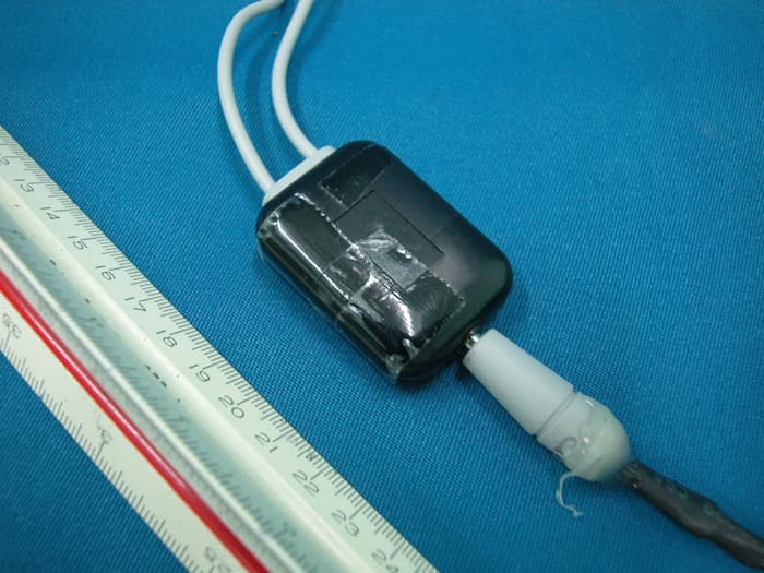
Click to zoom
Application Details
- Equipment Class
- DSS - Part 15 Spread Spectrum Transmitter
- Date of Grant
- Jan 04, 2010
- Application Purpose
- Original Equipment
- Date of Application
- Jan 04, 2010
- Equipment Note
- Portable Digital Wireless Stereo Headphones (Transmitter)
- Frequency Range
- 2404.32200000 - 2476.35000000
- Company
- RadioShack Corporation
- Country
- United States
Documents & Files
Document Text
Text extracted from the exhibit documents filed with the FCC. Open a document above to read the original.
Users Manual
THE P ERFORMANCE YOU NEED TM Portable Digital Wireless Stereo Headphones User’s Guide 33-283 Please read this user’s guide before using your new headphones. 2 2 3 3 4 4 5 5 6 6 7 7 8 b Battery Notes: Dispose of old batteries promptly and properly. Do not burn or bury them. Use only fresh batteries of the required size and recommended type. Do not mix old and new batteries of different sizes or types. If you do not plan to use the headphones for an extended time, remove the batteries. Batteries can leak chemicals that can damage electronic parts. When the power LED on the headphones turns off, replace your alkaline batteries or charge the rechargeable batteries. When using NiMH rechargeable batteries, capacity of 750mAh or above is recommended. 2 Charge 1. Connect the AC adapter plug into your charging hub’s DC 5.0V jack. 2. Connect the charging hub’s larger plug to your headphones’ jack. Make sure rechargeable batteries are installed and ALK/RCH is set to RCH. 3. Connect the charging hub’s smaller plug to your transmitter’s jack. 4. Connect the AC adapter to a standard power outlet. AUVIO logo on the charging hub flashes blue when charging and lights blue after charging. n Notes: Charge the built-in battery for at least 2 hours before the first time. Music does not play while charging. Charge your transmitter when the AUVIO logo does not light. Recycle your old rechargeable batteries at one of the many collection sites in the U.S. and Canada. To find the site nearest you, visit www.call2recycle.org or call toll-free 1-877-2-RECYCLE. Package contents Headphones Transmitter AC Adapter Charging Hub Carrying Pouch User’s Guide Quick Start Features Up to 30-foot (9.14m) wireless range (based on line-of- sight operation) Padded earcups and adjustable headband for comfort Charging hub charges the transmitter’s built-in battery, as well as the headphones if rechargeable batteries (not included) are used 1 Install batteries 1. Slide the battery compartment cover on the left ear cup in the direction of the arrow and open it. 2. Insert two AAA alkaline or NiMH rechargeable batteries (neither included), matching the polarity symbols (+ and –) marked. 3. Use a small tool to switch ALK/RCH to ALK for alkaline or RCH for rechargeable batteries. 4. Replace the cover. w Warning: Never install alkaline batteries with the ALK/RCH switch set to RCH. Alkaline batteries can get hot or explode if you try to recharge them. Power On/Off Turn on/off the headphones. Power LED Lights blue when the headphones are turned on. ON/OFF Turn on/off the transmitter. AUVIO logo lights blue when the transmitter is turned on. AUVIO logo flashes in blue when charging and lights blue after charging. 3 Use your headphones 1. Connect the transmitter to the 3.5mm headphones jack on your audio device. 2. Turn on the transmitter. AUVIO logo lights blue. 3. Turn on the headphones. The power LED lights blue. 4. Set the headphone volume to minimum. 5. Turn on the audio source, and gradually increase the volume to a comfortable level. nNotes: Remove objects between the transmitter and headphones. To preserve battery life, be sure to turn off the headphones and transmitter when you are not using them. Handling and Disposal: Do not burn or bury batteries. Do not puncture or crush. Do not disassemble. Recycle lithium batteries. Do not dispose of in the trash. Never allow loose cells to short circuit against battery tabs or other conductive items. Keep loose cells and battery packs out of reach of children. If the electrolyte in the cells should get on your skin, thoroughly wash with soap and water. If in the eyes, rinse thoroughly with cool water. Immediately seek medical attention. Charging Use only the supplied charging hub for the transmitter built-in lithium battery charging. Be sure the charging hub is powered by the provided AC adapter. Charge batteries on a fireproof surface away from flammable items or liquids. Do not charge inside an automobile, especially while driving. Follow the manufacturer’s instructions for charging the product and do not charge longer than recommended. Unplug the charger when the battery is charged. Listening Safely Set the headphone volume to the lowest setting before listening. After you begin listening, adjust the volume to a comfortable level. Do not listen at extremely high volume levels. Extended high- volume listening can lead to permanent hearing loss. If you connect the transmitter to an audio source headphone jack, set the audio source’s volume to the middle position. Then adjust VOLUME on the headphones to the desired level. Turn off the headphones before turning off the transmitter. This prevents you hearing a loud click that may be generated when you turn off the transmitter. Specifications Operating Frequency ......................................................2.4GHz Headphones Playtime .......................................... about 5 hours Frequency Response (6dB) .................................. 80Hz – 20KHz Audio S/N ........................................................................... 70dB Audio Resolution ............................................................... 16 bit Audio Sample Rate ....................................................... 44.1KHz Specifications are subject to change and improvement without notice. Actual product may vary from the product images in this document. FCC Information This equipment has been tested and found to comply with the limits for a Class B digital device, pursuant to Part 15 of the FCC Rules. These limits are designed to provide reasonable protection against harmful interference in a residential installation. This equipment generates, uses and can radiate radio frequency energy and, if not installed and used in accordance with the instructions, may cause harmful interference to radio communications. However, there is no guarantee that interference will not occur in a particular installation. If this eq…
Text truncated - open the document above for the full version.
External Photos
INTERTEK TESTING SERVICE Report No.: HK09101135-1 FCC ID: AAO330283T Equipment Photographs Model : 33-283 (External) INTERTEK TESTING SERVICE Report No.: HK09101135-1 FCC ID: AAO330283T Equipment Photographs Model : 33-283 (External) INTERTEK TESTING SERVICE Report No.: HK09101135-1 FCC ID: AAO330283T Equipment Photographs Model : 33-283 (External)
ID Label/Location Info
FCC ID Label and Location FCC ID: AAO330283T
Internal Photos
INTERTEK TESTING SERVICE Report No.: HK09101135-1 FCC ID: AAO330283T Equipment Photographs Model : 33-283 (Internal) INTERTEK TESTING SERVICE Report No.: HK09101135-1 FCC ID: AAO330283T Equipment Photographs Model : 33-283 (Internal) INTERTEK TESTING SERVICE Report No.: HK09101135-1 FCC ID: AAO330283T Equipment Photographs Model : 33-283 (Internal)
RF Exposure Info
INTERTEK TESTING SERVICE Report No.: HK09101135-1 FCC ID: AAO330283T RF Exposure Evaluation For Specific Absorption Rate (SAR) evaluation of the Transmitter Unit, with reference to TCB Exclusions List revised on July 17, 2002, portable transmitters with output power less than low threshold and operating within 2.5cm from person’s body can be certified by TCB without the SAR evaluation. The output power for portable transmitters is defined as the higher of the conducted or radiated (EIRP) source- based time averaging output power. And the low threshold is equal to (60/fGHz) mW for d < 2.5cm, where fGHz is mid-band frequency in GHz, and d is the distance from the portable transmitter to a person’s body, excluding hands, wrists, feet, and ankles. For the Transmitter Unit of the tested model of 33-283, the measured peak conducted power was 1.73 mW. The maximum source-based time averaging duty factor is 2.64%. The conducted source-based time averaging output power = (1.73 * 0.0264) mW = 0.046 mW The measured maximum field strength (FS) was 98.3 dBμV/m. The distance (D) between the antenna and the equipment under test (EUT) was 3 meters. From these data, the radiated (EIRP) source-based time-averaging output power can be calculated by: The radiated power = (FS*D)2 / 30 mW = 2.0 mW The radiated (EIRP) source-based time-averaging output power = (2.0 * 0.0264) mW = 0.054 mW The low threshold in the 2400 – 2483.5MHz band is 25 mW. From the above calculation, output power obtained in both method is less than low threshold, it is concluded that the handset can be certified by TCB without the SAR evaluation.
Test Report
INTERTEK TESTING SERVICES Report No.:HK09101135-1 Sample No.:1/2 Plot B2A: Low Channel 20 dB RF Bandwidth Plot B2B: Middle Channel 20 dB RF Bandwidth INTERTEK TESTING SERVICES Report No.:HK09101135-1 Sample No.:1/2 Plot B2C: High Channel 20 dB RF Bandwidth
Test Report
INTERTEK TESTING SERVICES Report No.:HK09101135-1 Sample No.:1/2 Plot B5A: Channel Occupancy Time Plot B5B: Channel Occupancy Time INTERTEK TESTING SERVICES Report No.:HK09101135-1 Sample No.:1/2 Plot B5C: Channel Occupancy Time Plot B5D: Channel Occupancy Time
Test Report
INTERTEK TESTING SERVICES Report No.:HK09101135-1 Sample No.:1/2 Plot B3A: Number of Hopping Frequencies Plot B3B: Number of Hopping Frequencies INTERTEK TESTING SERVICES Report No.:HK09101135-1 Sample No.:1/2 Plot B3C: Number of Hopping Frequencies Plot B3D: Number of Hopping Frequencies INTERTEK TESTING SERVICES Report No.:HK09101135-1 Sample No.:1/2 Plot B3E: Number of Hopping Frequencies
Test Report
Report no.: HK09101135-1 Charging Mode AC Mains Ctrl No.: N/A 150 kHz30 MHz 1 PK CLRWR 2 AV CLRWR SGL TDS 6DB dBμV dBμV AC RBW 9 kHz MT 10 ms PREAMP OFFAtt 10 dB AUTO 1 MHz10 MHz 0 10 20 30 40 50 60 70 80 90 100 CF15MAV CF15MQP HK09101136-1 (J11361A1) Date: 11.NOV.2009 00:43:54
Test Report
INTERTEK TESTING SERVICES Report No.:HK09101135-1 Sample No.:1/2 Plot B4: Channel Separation
Test Report
INTERTEK TESTING SERVICES Report No.:HK09101135-1 Sample No.:1/2 Plot B6A.1: Low Channel Emissions Plot B6A.2: Low Channel Emissions INTERTEK TESTING SERVICES Report No.:HK09101135-1 Sample No.:1/2 Plot B6B.1: Middle Channel Emissions Plot B6B.2: Middle Channel Emissions INTERTEK TESTING SERVICES Report No.:HK09101135-1 Sample No.:1/2 Plot B6C.1: High Channel Emissions Plot B6C.2: High Channel Emissions INTERTEK TESTING SERVICES Report No.:HK09101135-1 Sample No.:1/2 Plot B6D.1: Modulation Products Emissions at bandedges Plot B6D.2: Modulation Products Emissions at bandedges
Test Report
- The test report only allows to be revised within the retention period unless further standard or the requirement was noticed. - This report is for the exclusive use of Intertek's Client and is provided pursuant to the agreement between Intertek and its Client. Intertek's responsibility and liability are limited to the terms and conditions of the agreement. Intertek assumes no liability to any party, other than to the Client in accordance with the agreement, for any loss, expense or damage occasioned by the use of this report. Only the Client is authorized to permit copying or distribution of this report and then only in its entirety. Any use of the Intertek name or one of its marks for the sale or advertisement of the tested material, product or service must first be approved in writing by Intertek. The observations and test results in this report are relevant only to the sample tested. This report by itself does not imply that the material, product, or service is or has ever been under an Intertek certification program. Intertek Testing Services Hong Kong Ltd. 2/F., Garment Centre, 576 Castle Peak Road, Kowloon, Hong Kong. Tel: (852) 2173 8888 Fax: (852) 2785 5487 Website: www.hk.intertek-etlsemko.com TEST REPORT Report No.: HK09101135-1 RadioShack Corporation Application For Certification (Original Grant) (FCC ID: AAO330283T) Transceiver Prepared and Checked by: Approved by: Michael Leung Engineer Chan Chi Hung, Terry Lead Engineer Date: December 24, 2009 INTERTEK TESTING SERVICES Report No.: HK09101135-1 FCC ID: AAO330283T i GENERAL INFORMATION RadioShack Corporation BRAND NAME: AUVIO, MODEL: 33-283 FCC ID: AAO330283T Grantee: RadioShack Corporation Grantee Address: 300 RadioShack Circle, Mail Stop WF4-136, Fort Worth, Texas, 76102-2802, USA. Contact Person: Pat Loehr Tel: (817) 415-6221 Fax: (817) 415-9247 e-mail: N/A Manufacturer: N/A Manufacturer Address: N/A Brand Name: AUVIO Model: 33-283 Type of EUT: Transceiver Description of EUT: Portable Digital Wireless Stereo headphones (Transmitter) Serial Number: N/A FCC ID: AAO330283T Date of Sample Submitted: October 30, 2009 Date of Test: November 19, 2009 Report No.: HK09101135-1 Report Date: December 24, 2009 Environmental Conidtions: Temperature: +10 to 40°C Humidity: 10 to 90% INTERTEK TESTING SERVICES Report No.: HK09101135-1 FCC ID: AAO330283T ii SUMMARY OF TEST RESULT RadioShack Corporation BRAND NAME: AUVIO, MODEL: 33-283 FCC ID: AAO330283T TEST SPECIFICATION REFERENCE RESULTS Maximum Peak Output Power 15.247(b) Pass 20 dB Bandwidth 15.247(a) Pass Number of Hopping Frequencies 15.247(a) Pass Channel Separation 15.247(a) Pass Average Channel Occupancy Time 15.247(a) Pass Out of Band Antenna Conducted Emission 15.247(d) Pass Radiated Emission in Restricted Bands 15.247(d) Pass Radiated Spurious Emissions 15.247(d) Pass Transmitter Power Line Conducted Emissions 15.207 Pass Antenna Requirement 15.203 Pass (See Note 1) Digital Device Radiated Emission 15.109 Pass Digital Device Conducted Emission 15.107 Pass Note: 1. The EUT uses a permanently attached antenna which, in accordance to section 15.203, is considered sufficient to comply with the pervisions of this section. 2. Pursuant to FCC part 15 Section 15.215(c), the 20 dB bandwidth of the emission was contained within the frequency band designated (mentioned as above) which the EUT operated. The effects, if any, from frequency sweeping, frequency hopping, other modulation techniques and frequency stability over excepted variations in temperature and supply voltage were considered. INTERTEK TESTING SERVICES Report No.: HK09101135-1 FCC ID: AAO330283T iii Table of Contents 1.0 General Description........................................................................................ 1 1.1 Product Description ........................................................................................... 1 1.2 Related Submittal(s) Grants............................................................................... 1 1.3 Test Methodology.............................................................................................. 1 1.4 Test Facility ....................................................................................................... 1 2.0 System Test Configuration............................................................................. 2 2.1 Justification ....................................................................................................... 2 2.2 EUT Exercising Software................................................................................... 2 2.3 Special Accessories .......................................................................................... 2 2.4 Equipment Modification ..................................................................................... 2 2.5 Measurement Uncertainty.................................................................................. 2 2.6 Support Equipment List and Description ............................................................ 3 3.0 Emission Results............................................................................................ 3 3.1 Field Strength Calculation.................................................................................. 3 3.2 Radiated Emission Configuration Photograph.................................................... 4 3.3 Radiated Emission Data .................................................................................... 4 3.4 Conducted Emission Configuration Photograph................................................. 4 3.5 Conducted Emission Data ................................................................................. 4 4.0 Measurement Results..................................................................................... 5 4.1 Maximum Conducted Output Power at Antenna Terminals.................................. 5 4.2 Hopping Channel 20dB RF Bandwidth.............................................................. 5 4.3 Mini…
Text truncated - open the document above for the full version.
Test Setup Photos
INTERTEK TESTING SERVICE Report No: HK09101135-1 Configuration Photographs Worst-Case Line-Conducted Emissions (Front View) Model : 33-283 FCC ID: AAO330283T i INTERTEK TESTING SERVICE Report No: HK09101135-1 Configuration Photographs Worst-Case Line-Conducted Emissions (Back View) Model : 33-283 FCC ID: AAO330283T ii INTERTEK TESTING SERVICE Report No: HK09101135-1 Configuration Photographs Worst-Case Line-Conducted Emissions (Side View) Model : 33-283 FCC ID: AAO330283T iii
Test Setup Photos
INTERTEK TESTING SERVICE Report No: HK09101135-1 Configuration Photographs Worst-Case Radiated Emissions (Front View) Model : 33-283 (Transmit Mode) FCC ID: AAO330283T INTERTEK TESTING SERVICE Report No: HK09101135-1 Configuration Photographs Worst-Case Radiated Emissions (Back View) Model : 33-283 (Transmit Mode) FCC ID: AAO330283T INTERTEK TESTING SERVICE Report No: HK09101135-1 Configuration Photographs Worst-Case Radiated Emissions (Front View) Model : 33-283 (Charging Mode) FCC ID: AAO330283T INTERTEK TESTING SERVICE Report No: HK09101135-1 Configuration Photographs Worst-Case Radiated Emissions (Back View) Model : 33-283 (Charging Mode) FCC ID: AAO330283T
Contact Information
Applicant
Elizabeth Granados(Regulatory Affairs Manager)
Technical Contact
Intertek Testing Services Hong Kong LtdBen Ho
[email protected]852-21738505
2/F Garment Centre · Kowloon · Hong Kong
Non-Technical Contact
Intertek Testing Services Hong Kong LtdBen Ho
[email protected]852-21738505
Test Firm
Intertek Testing Services Hong Kong Ltd.Billy Chow
Technical Specifications
| # | Rule Parts | Frequency Range | Power Output |
|---|---|---|---|
| 1 | 15C | 2.40 GHz - 2.48 GHz | 1.73 mW |
Other Applications from RadioShack Corporation

AAO2302500
Feb 10, 2015Bluetooth Power Bank
Equipment Class
DXX - Part 15 Low Power Communication Device Transmitter
AAO4300124C
May 02, 2013900MHz Wireless Intercom
Equipment Class
DXT - Part 15 Low Power Transceiver, Rx Verified
AAO1200876
Nov 30, 2011Universal FM Transmitter
Equipment Class
DXX - Part 15 Low Power Communication Device Transmitter
AAO1200962
Aug 02, 2011Universal FM Transmitter
Equipment Class
DXX - Part 15 Low Power Communication Device Transmitter
AAO1500044T
Apr 02, 20112.4GHz Digital Wireless Rear Speaker Kit - Transmitter
Equipment Class
DSS - Part 15 Spread Spectrum Transmitter