AAO4303102900MHz Wireless Intercom
RadioShack Corporation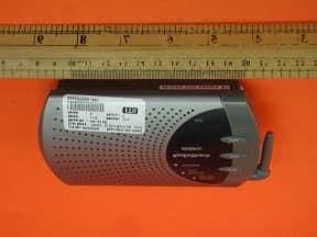
Click to zoom
Application Details
- Equipment Class
- DXT - Part 15 Low Power Transceiver, Rx Verified
- Date of Grant
- Apr 21, 2002
- Application Purpose
- Original Equipment
- Date of Application
- Apr 21, 2002
- Equipment Note
- 900MHz Wireless Intercom
- Frequency Range
- 910.00000000 - 913.00000000
- Company
- RadioShack Corporation
- Country
- United States
Documents & Files
Document Text
Text extracted from the exhibit documents filed with the FCC. Open a document above to read the original.
Users Manual
Cat. No. 43-3102 Owner’ Manual 900MHz Wireless Intercoms THE FCC WANTS YOU TO KNOW This device complies with Part 15 of the FCC Rules. Operation is subject to the following two conditions: (1) this device may not cause harmful interference, and (2) this device must accept any interference received, including interference that may cause undesired operation. Warning: Changes or modifications to this unit not expressly approved by the party responsible for compliance could void the user’s authority to operate the equipment. NOTE: This equipment has been tested and found to comply with the limits for a Class B digital device, pursuant to Part 15 of the FCC Rules. These limits are designed to provide reasonable protection against harmful interference in a residential installation. This equipment generates, uses and can radiate radio frequency energy and, if not installed and used in accordance with the instructions, may cause harmful interference to radio communications. However, there is no guarantee that interference will not occur in a particular installation. If this equipment does cause harmful interference to radio or television reception, which can be determined by turning the equipment off and on, the user is encouraged to try to correct the interference by one or more of the following measures: Reorient or relocate the receiving antenna. Increase the separation between the equipment and receiver. Connect the equipment into an outlet on a circuit different from that to which the receiver is needed. Consult the dealer or an experienced radio/TV technician for help. PREPARATION You can power your intercoms using four AA batteries (not supplied) or the supplied AC-to-DC adapter. Installing the Batteries Caution: Use only fresh batteries of the required size and recommended type. Do not mix old and new batteries, different types of batteries (standard, alkaline, or rechargeable), or rechargeable batteries of different capacities. 1. Remove the battery compartment door by sliding it toward the bottom of the unit. 2. Place four AA batteries in the compartment according to the polarity symbols (+ and -) marked inside. 3. Replace the cover. When the POWER BATT LOW LED flashes during the operation of the intercom, replace the batteries. Warning: Dispose of old batteries promptly and properly. Do not burn or bury them. Using AC-to-DC power Open battery compartment and remove batteries or make sure RECHARGE ON/OFF switch is set to OFF. Insert the barrel plug of the adapter into DC 9V jack on the back of the unit. Plug the other end of the adapter to a standard AC outlet. Using Rechargeable Batteries 1. Remove the battery compartment door. 2. Install the rechargeable batteries according to the polarity symbols (+ and -) marked on the battery compartment. 3. Slide RECHARGE ON/OFF to ON. 4. Replace the cover. Caution: Do not attempt to recharge alkaline batteries and regular batteries. Notes: O It takes about 10-12 hours to completely recharge the batteries. O The built-in charger is designed for batteries with 1.2V 1500mAh. O Once the unit has been turned on, the batteries will be automatically charged during the transmission mode and standby. O The battery life for rechargeable battery (Ni-MH, 1500mA) is about 37 hours . Mounting the Intercom You can install the stations almost anywhere and place it directly on a desk, shelf, and table or on a wall. Follow these steps to mount the intercom on a wall. Note: You need two screws (not supplied) with heads that fit into the keyhole slots on the bottom of the intercom. 1. Mark the mounting screw location 3 15/16 inches (100 mm) apart. 2. If you are installing on a drywall, use the correct dry wall screw lags for the screw size you are using. 3. Drill a hole for the drywall lag as recommended by the vendor at each mark. 4. Insert each drywall lag and tap with hammer to make it flush with wall. 5. Thread a screw into each hole or drywall insert until the left screw’s head extends about ¼ inch (6.5 mm) from the wall and the right screw’s head extends about 1/8 inch (3.5 mm) from the wall. 6. Align the keyhole slots on the bottom of the intercom with the screw heads in the wall, then slide the intercom to secure it. Lift and rotate the antenna upward. Important: Be sure you install the stations at least 10 feet away from each other. Placing the stations too close together produces feedback (a squeal or howl from the speakers). The stations can transmit up to 200 feet line of sight. Setting the Channel Each station has 4 pre-programmed channels, so you can select which channel you want to communicate on by setting the actuators of the channel selector (DIP switch) with different combination of ON and OFF. Set the channel selector on each station as follows: O If you want all the stations to communicate with each other at the same time, set all stations to the same channel. O If you want to use a station to communicate with only one of the other stations, set only those two stations to the same channel. CH 45 1 2 3 4 CH 45 1 2 3 4 Setting the Sub-tone Each station has 8 pre-programmed Sub-tones. You can select which sub-tone selector (DIP switch) with different combination of ON and OFF positions. Set the sub-tone selector on each station as follows: O If you want all the stations to communicate with each other at the same time, set all stations to the same sub-tone. O If you experience interference with the selected channel, set all stations to another desired sub-tone. OPERATION Turning the Intercom On and Off and Adjusting the Volume Rotate VOLUME counterclockwise until it clicks. The POWER/BATT LOW LED lights. Then adjust VOLUME to a comfortable listening level. ON SUB. TONE 1 1 2 3 4 5 6 7 8 23 O The POWER/BATT LOW LED will flash when the battery is low. To turn off the intercom, rotate VOLUME clockwise until it clicks. The POWER/BATT LOW LED turns off. Calling Another Station O Be sure the station you plan to use are turned on and adjusted to the desir…
Text truncated - open the document above for the full version.
External Photos
Test SetupFCCID : AAO4303102 External Photo -front External Photo - rear
Internal Photos
Test SetupFCCID : AAO4303102 Internal Photo - 1 Internal Photo – 2 Test SetupFCCID : AAO4303102 Internal Photo - 3 Internal Photo - 4 Test SetupFCCID : AAO4303102 Internal Photo – 5 Internal Photo – 6 Test SetupFCCID : AAO4303102 Internal Photo - 7 Internal Photo – 8 Test SetupFCCID : AAO4303102 Internal Photo – 9
Test Report
• The test results reported in this test report shall refer only to the sample actually tested and shall not refer or be deemed to refer to bulk from which such a sample may be said to have been obtained. • This report shall not be reproduced except in full without prior authorization from Intertek Testing Services Hong Kong Limited. • For Terms And Conditions of the services, it can be provided upon request. Intertek Testing Services Hong Kong Ltd. 2/F., Garment Centre, 576 Castle Peak Road, Kowloon, Hong Kong. Tel: (852) 2173 8888 Fax: (852) 2785 5487 RadioShack Corporation Application For Certification (FCC ID: AAO4303102) Transmitter WO# 0202556 WL/Sandy April 9, 2002 INTERTEK TESTING SERVICES FCC ID: AAO4303102 i LIST OF EXHIBITS INTRODUCTION EXHIBIT 1:General Description EXHIBIT 2:System Test Configuration EXHIBIT 3:Emission Results EXHIBIT 4:Equipment Photographs EXHIBIT 5:Product Labelling EXHIBIT 6:Technical Specifications EXHIBIT 7:Instruction Manual EXHIBIT 8:Miscellaneous Information INTERTEK TESTING SERVICES FCC ID: AAO4303102 ii MEASUREMENT/TECHNICAL REPORT RadioShack Corporation - MODEL: RadioShack 43-3102 FCC ID: AAO4303102 April 9, 2002 This report concerns (check one:)Original Grant X Class II Change Equipment Type: Low Power Transmitter (example: computer, printer, modem, etc.) Deferred grant requested per 47 CFR 0.457(d)(1)(ii)?Yes No X If yes, defer until: date Company Name agrees to notify the Commission by: date of the intended date of announcement of the product so that the grant can be issued on that date. Transition Rules Request per 15.37?Yes No X If no, assumed Part 15, Subpart C for intentional radiator - the new 47 CFR [12-18-01 Edition] provision. Report prepared by:Wilson Loke Intertek Testing Services 2/F., Garment Center, 576, Castle Peak Road, HONG KONG Phone:852-2173-8575 Fax:852-2371-0521 INTERTEK TESTING SERVICES FCC ID: AAO4303102 iii Table of Contents 1.0 General Description............................................................................................................2 1.1 Product Description............................................................................................................2 1.2 Related Submittal(s) Grants.................................................................................................2 1.3 Test Methodology...............................................................................................................3 1.4 Test Facility........................................................................................................................3 2.0 System Test Configuration.................................................................................................5 2.1 Justification.........................................................................................................................5 2.2 EUT Exercising Software....................................................................................................5 2.3 Special Accessories............................................................................................................5 2.4 Equipment Modification......................................................................................................6 2.5 Measurement Uncertainty....................................................................................................6 2.6 Support Equipment List and Description..............................................................................6 3.0 Emission Results.................................................................................................................8 3.1 Field Strength Calculation....................................................................................................9 3.2 Radiated Emission Configuration Photograph.....................................................................11 3.3 Radiated Emission Data....................................................................................................12 3.4 Conducted Emission Configuration Photograph..................................................................14 3.5 Conducted Emission Data.................................................................................................15 4.0 Equipment Photographs....................................................................................................17 5.0 Product Labelling..............................................................................................................19 6.0 Technical Specifications....................................................................................................21 7.0 Instruction Manual............................................................................................................23 8.0 Miscellaneous Information...............................................................................................25 8.1 Bandedge Plot..................................................................................................................26 8.2 Discussion of Pulse Desensitization....................................................................................27 8.3 Emissions Test Procedures................................................................................................28 INTERTEK TESTING SERVICES FCC ID: AAO4303102 iv List of attached file Exhibit typeFile Descriptionfilename Test ReportTest Reportreport.pdf Operation DescriptionTechnical Descriptiondescri.pdf Test Setup PhotoRadiated Emissionradiated photos.doc Test Setup PhotoConducted Emissionconducted photos.doc Test ReportConducted Emission Test Resultconduct.pdf Test ReportBandedge Plotbw.pdf External PhotoExternal Photoexternal photos.doc Internal PhotoInternal Photointernal photos.doc Block DiagramBlock Diagramblock.pdf SchematicsCircuit Diagramcircuit.pdf ID Label/LocationLabel Artwork and Locationlabel.pdf User ManualUser Manualmanual.pdf INTERTEK TESTING SERVICES FCC ID: AAO4303102 1 EXHIBIT 1 GE…
Text truncated - open the document above for the full version.
Test Setup Photos
Test SetupFCCID : AAO4303102 Radiated -front Radiated - rear
Test Setup Photos
Test SetupFCCID : AAO4303102 Conduct Photo - 1 Conduct Photo - 2 Test SetupFCCID : AAO4303102 Conduct Photo – 3
Contact Information
Applicant
Elizabeth Granados(Regulatory Affairs Manager)
Technical Contact
Intertek Testing Services Hong Kong Ltd.Wilson Loke
[email protected]852-2173-8575
2/F., Garment Centre, · Kowloon · Hong Kong
Non-Technical Contact
Intertek Testing Services Hong Kong Ltd.Wilson Loke
[email protected]852-2173-8575
Test Firm
Intertek Testing Services Hong KongBilly Chow
Technical Specifications
| # | Rule Parts | Frequency Range | Power Output |
|---|---|---|---|
| 1 | 15C | 910 MHz - 913 MHz | - |
Other Applications from RadioShack Corporation

AAO2302500
Feb 10, 2015Bluetooth Power Bank
Equipment Class
DXX - Part 15 Low Power Communication Device Transmitter
AAO4300124C
May 02, 2013900MHz Wireless Intercom
Equipment Class
DXT - Part 15 Low Power Transceiver, Rx Verified
AAO1200876
Nov 30, 2011Universal FM Transmitter
Equipment Class
DXX - Part 15 Low Power Communication Device Transmitter
AAO1200962
Aug 02, 2011Universal FM Transmitter
Equipment Class
DXX - Part 15 Low Power Communication Device Transmitter
AAO1500044T
Apr 02, 20112.4GHz Digital Wireless Rear Speaker Kit - Transmitter
Equipment Class
DSS - Part 15 Spread Spectrum Transmitter