AAO4303107900 MHz Door Bell w/AC Line Intercom-Indoor Unit
RadioShack Corporation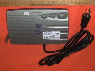
Click to zoom
Application Details
- Equipment Class
- DXT - Part 15 Low Power Transceiver, Rx Verified
- Date of Grant
- Sep 17, 2002
- Application Purpose
- Original Equipment
- Date of Application
- Sep 17, 2002
- Equipment Note
- 900 MHz Door Bell w/AC Line Intercom-Indoor Unit
- Frequency Range
- 912.45000000 - 914.45000000
- Company
- RadioShack Corporation
- Country
- United States
Documents & Files
Document Text
Text extracted from the exhibit documents filed with the FCC. Open a document above to read the original.
Users Manual
43-3107 OWNER’S MANUAL — Please read before using this equipment. © 2001 RadioShack Corporation. All Rights Reserved. RadioShack and RadioShack.com are trademarks used by RadioShack Corporation. Indoor/Outdoor Modular Intercom System Your Indoor/Outdoor Modular Intercom System operates as a two-tone doorbell intercom and an indoor intercom. The doorbell is simple to install without wiring and you can add additional stations. PREPARATION Installing the Doorbell’s Batteries Your doorbell intercom uses four AA batteries (not supplied) for power. For the best performance and longest life, we recommend RadioShack alkaline batteries. Caution: Use only fresh batteries of the required size and recommended type. Do not mix old and new batteries, different types of batteries (standard, alkaline, or rechargeable), or rechargeable batteries of different capacities. 1. Use a Phillips screwdriver to loosen the screws in the doorbell intercom’s battery compartment cover, then lift the cover off. 2. Insert four AA batteries into the compartment as indicated by the polarity symbols ( + and – ) marked inside. 3. Replace the cover and tighten the screws. Hint: For convenience, set the channel (see “Setting the Channel”) while you have the battery cover removed. Warning: Dispose of old batteries promptly and properly. Do not burn or bury them. Caution: If you do not plan to use the doorbell for two weeks or longer, remove the batteries. Batteries can leak chemicals that can destroy electronic parts. If the doorbell unit operates under severe cold weather, use a lithuim type AA battery. Setting the Channel The doorbell and indoor intercoms have three selectable operation channels to prevent interference from similar products nearby. Select the same channel for both the doorbell intercom and the indoor intercom. On the doorbell intercom, slide CH inside the battery compartment to 1 (912.45MHz), 2 (913.45MHz), or 3 (914.45MHz). On the back of the indoor intercom, set OUTDOOR CHANNEL to the same channel number ( 1 , 2 or 3 ) you chose for the doorbell intercom. Note: If the doorbell occasionally sounds without anyone pressing BELL on the doorbell, change the channel settings. Changing the Doorbell’s Tone Use a small flat-blade screwdriver to carefully pull out the jumper TONE switch located in the battery compartment, then insert the jumper TONE switch into the other two pins. 43-3101.fm Page 1 Friday, November 9, 2001 8:30 AM 2 Setting the Doorbell’s Volume Slide VOL located inside the battery compartment to level 1 , 2 or 3 . Testing the Doorbell Test the doorbell before permanently mounting it. With the indoor intercom plugged into a standard AC outlet, adjust VOLUME on the indoor intercom to its middle position. Press BELL on the doorbell intercom. The doorbell should sound. Mounting the Doorbell 1. Drill four 3 / 16 inch diameter holes into the mounting surface. Insert an anchor into each hole. 2. Align the supplied metal mounting bracket with the drilled holes and drive a screw (supplied) through the bracket into each hole. Do not overtighten the screws. 3. Align the slot on the back of the doorbell with the hook on the mounting bracket. Carefully push the doorbell onto the hook and slide it down to secure it. 4. Once the doorbell is securely on the bracket, insert the pan-head machine screw (supplied) through the hole on the lower edge of the doorbell into the threaded holes in the bracket. Mounting the Indoor Intercom Follow these steps to mount the indoor intercom on a wall. Note: You need two screws (supplied) with heads that fit into the keyhole slots on the bottom of the intercom. 1. Mark the mounting screw locations 2 1 / 2 inches (64 mm) apart, one above the other. 2. Drill a starter hole at each mark. 3. Thread a screw into each hole until the screw’s head extends about 1 / 8 inch (3.5mm) from the wall. 4. Align the keyhole slots on the bottom of the intercom with the screw heads in the wall, then slide the intercom down to secure it and lift and extend the antenna. Connecting the Indoor Intercom to AC Power Locate a standard AC outlet in the area where you want to hear the chime and use the intercom. Plug the indoor intercom’s power cord into the outlet. Caution: This product is equipped with a three-wire grounding-type plug ( a plug having a third grounding pin). This plug will only fit into a grounding-type power outlet. This is a safety feature. If you are unable to insert the plug into your AC outlet, contact your electrician to replace your outlet. Do not defeat the safety purpose of the grounding- type plug. Important: Be sure you install the stations at least 10 feet away from each other. Placing the stations too close together produces feedback (a squeal or howl from the speakers). The stations can transmit up to 300 feet, including between buildings, as long as they are connected to the same power line transformer. OPERATION Turning the Indoor Intercom On and Off and Adjusting the Volume Rotate VOLUME counterclockwise until it clicks. The POWER indicator lights. Then adjust VOLUME to the desired listening level. To turn off the indoor intercom, rotate VOLUME clockwise until it clicks. The POWER indicator turns off. 43-3101.fm Page 2 Friday, November 9, 2001 8:30 AM 3 Using the Doorbell Your visitor presses BELL on the doorbell to sound the doorbell. Hold down TALK TO DOOR on the indoor intercom to reply to the caller. The TALK TO DOOR indicator lights. When you release TA LK TO DOOR , the caller can reply by pressing PRESS TO TALK on the doorbell intercom. Notes: • If there is no voice communication between the doorbell and the indoor intercom within about 10 seconds, the doorbell intercom may be disabled and should be initialized by pressing BELL again. • You can also use other intercoms to reply to the doorbell as long as they are set on the same frequency. • If the channel is occupied by other intercom users, the door chime cannot be sent to the intercoms in use. The conversation bet…
Text truncated - open the document above for the full version.
Block Diagram
43-3107 Indoor Unit Block Diagram MIC_Mute Q305 MCU Data in 4MHz Resonator Reset cct Talk button Talk to Bell LEDs RF Ch. SW TX On RX Mute Input/Output coupling cct Limiter1 RX amp1 Limiter2 RX amp2 LPF RX_SW TX Amp PLL (U305) Channel SW Call Button AC Power regulator Vcc Call tone Limiter Mic Mute Audio_On Carrier Det (AC) Call tone D301-304 U306 U309 U303F U308 U303A Q306 Inverter Q316 Audio_On V+ V+ MIC SW MIC amp1 MIC amp2 U303E Audio combine network Call tone U303D U310 AC audio amp1 (Q313) RF_Mod AC audio amp2 (Q315) Q308 Q309 V+ TX_Mute Q307 TX_Mute Inverter TX_Mute Q314 TX_mute1 Tx_mute1 Tx_V+ RF_Aud RF module PLL(data, clk, stb) RF_aud Amp Data Amp RF audio U303C U303B Vcc FM_Demod SQL TX/RX SW RX_V+TX_V+ RF_Mod Audio power amp (U304) Q304, Q310, Q311 43-3107 Indoor Unit RF Block Diagram LPF LNA (Q201,Q202) 913MHz SAW Filter Mixer (U201) 10.7MHz filter IF Amp (Q203) 10.7MHz filter FM demo IC (U202) Q204, Q205 PLL IC (U203) TX Amp (Q206) TX Amp(Q207) Switching diode (D202) RX_3.5V Vcc TX_V+ SQL CCT (U302) RF_MOD SQL 4MHz XTAL PLL (data,clk, stb) FM_Demod
External Photos
Test SetupFCCID : AAO4303107 External Photo -front External Photo - rear
Internal Photos
Test SetupFCCID : AAO4303107 Internal Photo - 1 Internal Photo - 2 Test SetupFCCID : AAO4303107 Internal Photo – 3 Internal Photo – 4 Test SetupFCCID : AAO4303107 Internal Photo – 5 Internal Photo – 6
Operational Description
43-3107 Indoor Unit circuit description The indoor unit composes of RF circuit part and AC intercom circuit part. RF circuit part operates at 912.45 to 914.45MHz with channel spacing 1MHz. While the AC intercom circuit part operates at 200 to 270KHz. The channel frequency allocation is that channel 1 operates at 200KHz. Channel 2 operates at 270KHz. Channel 3 is operates at 230KHz. RF transmitter section: The transmitter VCO composes of transistor Q205, varactor diodes VD201 and PLL IC (U203). The function of the PLL IC (U203) is to lock the desired channel frequency set by MCU. The operation channel frequencies are 912.45MHz, 913.45MHz and 914.45MHz for 3 channels with 1MHz channel spacing. The VCO output is amplified by buffer amplifier Q204 and then further amplified by the power amplifiers Q206 and Q207 respectively. The amplified signal passes through the antenna switching diodes of D202 and then being fed to antenna. RX section: The receiver amplifier composes of Q201 and Q202. The received RF signal is amplified by Q201 and Q202 and then being feed into 914MHz SAW filter to cut the image frequency. The output from the 914MHz SAW filter is then applied to mixer IC U201 (uPC2757T). The function of the mixer IC (uPC2757T) is to down convert the input frequency to 10.7MHz IF frequency. The output IF frequency is applied to 10.7MHz ceramic filter (FIL2) and then being amplified by IF amplifier (Q4). The amplified IF signal is applied to FM demodulation IC U1 (TA31161). The demodulated base-band signal is applied to squelch circuit U302A and U302B (LMV324/LMP324) and audio power amplifier U304 (MC34119). Part of the demodulated signal is applied to U305 (NE567) to be modulated with AC intercom carrier frequency. The audio cut off is controlled by squelch circuit formed by U302A and U302B (LM358), U307 (BAV99). TX modulation: The audio input signal is amplified by mic amplifier U303E and U303D and then being feed to TX VCO and U305 (NE567) via Q313. The RF deviation can be adjusted by tuning variable resistor (VR301). Transistor switches: Transistors Q304, Q310 and Q311 act as switch that control TX_V+ and RX_V+ on and off. Transistors Q307 controls the AC intercom signal transmit on and off. Transistors Q306 and Q316 acts as muting circuit that controls the receiving AC intercom signal on and off. Transistor Q305 acts as mic muting switch that controls the mic input on and off. AC intercom circuit TX operation: The AC intercom transmit frequency generate by U305 (NE567) which acts as frequency synthesizer and FM demodulator. The generated AC intercom signal is amplified by Q308 and then further amplified by power amplifier Q309. The amplified signal passes through low pass filter formed by L304-L307. Finally, the signal is coupled to AC line via transformer T301. RX operation: The received signal is applied to input pin of the amplifier (pin 13 of U303F) via transformer T102. The amplified signal is further amplified by U303A and then coupled to FM demodulator IC NE567. The demodulated signal is then applied to audio amplifier U8 (LM386). The audio level can be controlled by volume control VR302. Frequency tuning: The operation frequencies of AC intercom can be adjusted by tuning VR303, VR304 and VR305 for channel 1, channel 3 and channel 2 respectively.
Schematics
3107INV3.SCH-1 - Fri Aug 16 17:20:29 2002 3107INV3.SCH-2 - Fri Aug 16 17:21:35 2002
Test Report
• The test results reported in this test report shall refer only to the sample actually tested and shall not refer or be deemed to refer to bulk from which such a sample may be said to have been obtained. • This report shall not be reproduced except in full without prior authorization from Intertek Testing Services Hong Kong Limited. • For Terms And Conditions of the services, it can be provided upon request. • The evaluation data of the report will be kept for 3 years from the date of issuance. Intertek Testing Services Hong Kong Ltd. 2/F., Garment Centre, 576 Castle Peak Road, Kowloon, Hong Kong. Tel: (852) 2173 8888 Fax: (852) 2785 5487 RadioShack Corporation Application For Certification (FCC ID: AAO4303107) Transmitter WO# 0210889 DL/Sandy September 6, 2002 INTERTEK TESTING SERVICES FCC ID: AAO4303107 i LIST OF EXHIBITS INTRODUCTION EXHIBIT 1: General Description EXHIBIT 2: System Test Configuration EXHIBIT 3: Emission Results EXHIBIT 4: Equipment Photographs EXHIBIT 5: Product Labelling EXHIBIT 6: Technical Specifications EXHIBIT 7: Instruction Manual EXHIBIT 8: Miscellaneous Information INTERTEK TESTING SERVICES FCC ID: AAO4303107 ii MEASUREMENT/TECHNICAL REPORT RadioShack Corporation - MODEL: RadioShack 43-3107 FCC ID: AAO4303107 September 6, 2002 This report concerns (check one:) Original Grant X Class II Change Equipment Type: Low Power Transmitter (example: computer, printer, modem, etc.) Deferred grant requested per 47 CFR 0.457(d)(1)(ii)? Yes No X If yes, defer until: date Company Name agrees to notify the Commission by: date of the intended date of announcement of the product so that the grant can be issued on that date. Transition Rules Request per 15.37? Yes No X If no, assumed Part 15, Subpart C for intentional radiator - the new 47 CFR [12-18-01 Edition] provision. Report prepared by: Derek Leung Intertek Testing Services 2/F., Garment Center, 576, Castle Peak Road, HONG KONG. Phone: 852-2173-8504 Fax: 852-2371-0521 INTERTEK TESTING SERVICES FCC ID: AAO4303107 iii Table of Contents 1.0 General Description ............................................................................................................2 1.1 Product Description..........................................................................................................2 1.2 Related Submittal(s) Grants...............................................................................................2 1.3 Test Methodology.............................................................................................................3 1.4 Test Facility......................................................................................................................3 2.0 System Test Configuration ...............................................................................................5 2.1 Justification.......................................................................................................................5 2.2 EUT Exercising Software..................................................................................................5 2.3 Special Accessories..........................................................................................................5 2.4 Equipment Modification....................................................................................................6 2.5 Measurement Uncertainty....................................................................................................6 2.6 Support Equipment List and Description............................................................................6 3.0 Emission Results ...............................................................................................................8 3.1 Field Strength Calculation..................................................................................................9 3.2 Radiated Emission Configuration Photograph...................................................................11 3.3 Radiated Emission Data..................................................................................................12 3.4 Conducted Emission Configuration Photograph................................................................14 3.5 Conducted Emission Data...............................................................................................15 4.0 Equipment Photographs ..................................................................................................17 5.0 Product Labelling ............................................................................................................19 6.0 Technical Specifications ..................................................................................................21 7.0 Instruction Manual ..........................................................................................................23 8.0 Miscellaneous Information .............................................................................................25 8.1 Bandedge Plot................................................................................................................26 8.2 Discussion of Pulse Desensitization..................................................................................27 8.3 Emissions Test Procedures..............................................................................................28 INTERTEK TESTING SERVICES FCC ID: AAO4303107 iv List of attached file Exhibit type File Description filename Test Report Test Report report.pdf Operation Description Technical Description descri.pdf Test Setup Photo Radiated Emission radiated photos.doc Test Setup Photo Conducted Emission conducted photos.doc Test Report Conducted Emission Test Result conducted.pdf Test Report Bandedge Plot bw.pdf External Photo External Photo external photos.doc Internal Photo Internal Photo internal photos.doc Block Diagram Block Diagram block.pdf Schematics Circuit Diagram circuit.pdf ID Label/Location Label Artwork and Location label…
Text truncated - open the document above for the full version.
Test Setup Photos
Test SetupFCCID : AAO4303107 Radiated -front Radiated - rear
Contact Information
Applicant
Elizabeth Granados(Regulatory Affairs Manager)
Technical Contact
Intertek Testing Services Hong Kong Ltd.Derek Leung
[email protected]852 2173 8504
2/F, Garment Centre · Kowloon · Hong Kong
Non-Technical Contact
Intertek Testing Services Hong Kong Ltd.Derek Leung
[email protected]852 2173 8504
Test Firm
Intertek Testing Services Hong KongBilly Chow
Technical Specifications
| # | Rule Parts | Frequency Range | Power Output |
|---|---|---|---|
| 1 | 15C | 912.45 MHz - 914.45 MHz | - |
Other Applications from RadioShack Corporation

AAO2302500
Feb 10, 2015Bluetooth Power Bank
Equipment Class
DXX - Part 15 Low Power Communication Device Transmitter
AAO4300124C
May 02, 2013900MHz Wireless Intercom
Equipment Class
DXT - Part 15 Low Power Transceiver, Rx Verified
AAO1200876
Nov 30, 2011Universal FM Transmitter
Equipment Class
DXX - Part 15 Low Power Communication Device Transmitter
AAO1200962
Aug 02, 2011Universal FM Transmitter
Equipment Class
DXX - Part 15 Low Power Communication Device Transmitter
AAO1500044T
Apr 02, 20112.4GHz Digital Wireless Rear Speaker Kit - Transmitter
Equipment Class
DSS - Part 15 Spread Spectrum Transmitter