AAO43035192.4 GHz Direct Sequence SS Cordless Phone
RadioShack Corporation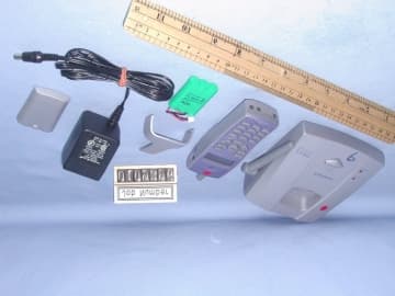
Click to zoom
Application Details
- Equipment Class
- DSS - Part 15 Spread Spectrum Transmitter
- Date of Grant
- Nov 25, 2001
- Application Purpose
- Original Equipment
- Date of Application
- Nov 25, 2001
- Equipment Note
- 2.4 GHz Direct Sequence SS Cordless Phone
- Frequency Range
- 2404.80000000 - 2475.00000000
- Company
- RadioShack Corporation
- Country
- United States
Documents & Files
Document Text
Text extracted from the exhibit documents filed with the FCC. Open a document above to read the original.
Users Manual
FCC REQUIREMENTS This equipment complies with Part 68 of the FCC Rules. On the bottom or back of this equipment is a label that contains, among other information, the FCC Registration Number and Ringer Equivalence Number (REN) for this equipment. Upon request, you must provide this information to your telephone company. The USOC number of the registration jack for the equipment is RJ11C. A FCC compliant telephone cord and modular plug is provided with this equipment. This equipment is designed to be connected to the telephone network or promises wiring using a compatible modular jack which is Part 68 compliant. See Installation Instructions for details. The REN is useful to determine the quantity of devices you may connect to your telephone line and still have all of those devices ring when your telephone number is called. In most, but not all areas, the sum of the RENs of all devices connected to one line should not exceed five (5). If your telephone equipment causes harm to the telephone network, the telephone company may discontinue your service temporarily. If possible, they will notify you in advance. If advanced notice isn’t practical, you will be notified as soon as possible. You will be informed of your right to file a complaint with the FCC. Your telephone company may make changes in its facilities, equipment, operations or procedures that could affect the proper functioning of your equipment. If they do, you will be notified in advance to give you an opportunity to maintain uninterrupted telephone service. If you experience trouble with this telephone equipment, disconnected this equipment from the network until you are sure the equipment is not malfunctioning This equipment may not be used on coin service provided by the telephone company. Connection to party lines is subject to state tariffs. This equipment if it uses a telephone handset is hearing aid compatible Please follow instructions for repairing if any (e.g. battery replacement section), otherwise do not alternate or repair any parts of device except specified. WARNING : Changes or modifications to this unit not expressly approved by the party responsible for compliance could void the user’s authority to operate the equipment. NOTE : This equipment has been tested and found to comply with the limits for a Class B digital device, pursuant to Part 15 of the FCC Rules. These limits are designed to provide reasonable protection against harmful interference in a residential installation. This equipment generates, uses and can radiate radio frequency energy and, if not installed and used in accordance with the instructions, may cause harmful interference to radio communications. However there is no guarantee that interference will not occur in a particular installation. If this equipment does cause harmful interference to radio or television reception which can be determined by turning the equipment off and on, the user in encouraged to try to correct the interference by one or more of the following measures. Reorient or relocate the receiving antenna. Increase the separation between the equipment and receiver. Connect the equipment in to an outlet on a circuit different from that to which the receiver is needed. Consult the dealer or experienced radio/TV technical for help. FCC REQUIREMENTS - continued RF SAFETY INFORMATION Important : To maintain compliance with the FCC’s exposure guidelines, please read the following specific operating instruction. Base The antenna(s) used for this transmitter must be installed to provide a separation distance of at least 20 cm from all persons and must not be co-located or operating in conjunction with any other antenna or transmitter. Handset This device and its antenna(s) must not be co-located or operating in conjunction with any other antenna or transmitter. This device complies with Part 15 of the FCC Rules. Operation is subject to the following two conditions: (1) this device may not cause harmful interference, and (2) this device must accept any interference received, including interference that may cause undesired operation. Privacy of communications may not be ensured when using this phone.
Cover Letter(s)
To:Tommy Leung ITS/ES-HKG Cc:Danielle Gravelle ITS/ES-Box; Kid Wong ITS/ES-HKG Subject: RE: RadioShack DSSS Phone FCC ID: AAO4303519 Dear Tommy: Thank you for the detailed response. My comments are below. Regards, Roland -----Original Message----- From:Tommy Leung ITS/ES-HKG Sent:Wednesday, November 21, 2001 6:09 AM To:Roland Gubisch ITS/ES-Box Cc:Danielle Gravelle ITS/ES-Box; Kid Wong ITS/ES-HKG Subject: RE: RadioShack DSSS Phone FCC ID: AAO4303519 Dear Roland, Thanks for your prompt reply!! For point 5) We are pending the confirmation from our client and the suggested statements are as follows: RF SAFETY INFORMATION Important: To maintain compliance with the FCC's RF exposure guidelines, please read the following specific operating instructions. HANDSET This device and its antenna(s) must not be co-located or operating in conjunction with any other antenna or trans mi tter. BASE The antenna(s) used for this transmitter must be installed to provide a separation distance of at least 20 cm from all persons and must not be co-located or operating in conjunction with any other antenna or trans mi tter. This RF safety information is excellent. When the client approves, please send a copy of the revised user ma n ua l The other points are replied as follows: 1) Since all out of band emissions are evaluated by the RF conducted method (except emissions fall in the restricted bands), the column is reported "N/A". I agree to amend the table and will submit with item 7). OK 2) I will amend it accordingly. OK 3) Yes. We had evaluated the peak limits and will amend the pages. OK 4) Yes. I will amend that pages. OK If you need other information, please feel free to contact me. Thanks and best regards, To mmy. Intertek Testing Services (HK) Ltd. Tel: 852-2173-8538 Pager: 7302-3113 Fax: 852-2741-1693 E-mail: [email protected] -----Original Message----- From: Roland Gubisch ITS/ES-Box Sent:Tuesday, November 20, 2001 8:30 AM To:Kid Wong ITS/ES-HKG Cc:Tommy Leung ITS/ES-HKG; Wilbur Ng ITS/ES-HKG; Danielle Gravelle ITS/ES-Box Subject: RadioShack DSSS Phone FCC ID: AAO4303519 Dear Kid Wong: Technical review of the 2.4 GHz cordless phone is complete and the following points are noted: 1) Section 1.0 Summary of tests: Out of band radiated emissions 15.247(c) is reported as "Not applicable" yet it is measured on pages 22, 23, 24, 27, 28 and 29. The statement should be changed to "Pass." 2) All radiated emission data tables: Note 1 says "peak detector data" and Note 4 says "average detector above 1000 MHz." Both cannot be true. Please amend Note 1 to read: "Peak detector used below 1000 MHz." 3) Radiated emission limits above 1000 MHz are subject to both average limits and peak limits, per 15.35(b). Please address compliance to peak limits on pages 22, 23, 24, 27, 28 and 29. 4) Processing gain data for the base unit does not show the necessary 50 kHz frequency increments, as shown in the handset data. Please review and correct. 5) 150247(b)(4) requires compliance with RF exposure limits. For the base unit, a 20 cm separation distance is assumed. If there are no precaution in the user manual, please amend the manual or provide addenda. For guidance, the Grant Notes for this system will appear like this: This device and its antenna(s) must not be co-located or operating in conjunction with any other antenna or transmitter. The antenna(s) used for the base transmitter must be installed to provide a separation distance of at least 20 cm from all persons. End-users must be provided with specific operating instructions for satisfying RF exposure compliance. Regards, Roland
External Photos
External photos FCC ID: AAO4303519 External photos FCC ID: AAO4303519
Internal Photos
Internal photosFCC ID: AAO4303519 Base assembly Base Main PCB comp s ide Internal photosFCC ID: AAO4303519 Base Main PCB solder side Base Oscillator PCB co mp side Internal photosFCC ID: AAO4303519 Base Oscillator PCB so lde r side Internal photosFCC ID: AAO4303519 Ha ndse t asse mbly Ha ndse t Main PCB co mp s ide Internal photosFCC ID: AAO4303519 Handset Main PCB display side Ha ndse t Oscillato r PCB co mp s ide Internal photosFCC ID: AAO4303519 Ha ndse t Oscillato r PCB solde r side
RF Exposure Info
RF Safety information Maximum Conducted Output Power (mW) Measured Maximum F ield Strength @ 3m (dB μ μμ μ V/m) Calculated EIRP (mW) Base Unit30.8108.119.4 Handset12.6103.87.2 The 43-3519 operates at frequency range of 2404.8 MHz to 2475.0MHz. From the above data, the maximum conducted power of the base unit is 30.8mW and the calculated EIRP is 19.4mW. The maximum conducted power of the handset is 12.6mW and the calculated EIRP is 7.2mW. These low energy level ensures that the public is not exposed to radio frequency energy levels in excess of the Commission’s guild lines as stipulated in Parts 1.1307(b)(1) and 2.1093.
Test Report
• The test results rep orted in this rep ort shall refer only to the samp le actually tested and shall not refer or be deemed to refer to bulk from which such a samp le may be said to have been obtained. • This rep ort shall not be rep roduced excep t in full without p rior authorization form Giant Electronics Limit ed Limit ed FCC ID: AAO4303519 Inte rte k Te sting Se rvice s Hong Kong Ltd. 2/F., Garment Centre, 576 Castle Peak Road, Kowloon, Hong Kong. Tel: (852) 2173 8888 Fax: (852) 2741 1693 RadioShack Corporation Application For Certification 2.4GHz Direct Sequence Spread Spectrum Cordless Phone (FCC ID: AAO4303519) WO# 0109396 WL/Ann Choy October 26, 2001 INTERTEK TESTING SERVICE FCC ID: AAO4303519 i LIST OF EXHIBITS INTRODUCTION EXHIBIT 1: Summary of Tests EXHIBIT 2 :General Description EXHIBIT 3 :System Test Configuration EXHIBIT 4 :Measurement Results EXHIBIT 5 :Equipment Photographs EXHIBIT 6 :Product Labelling EXHIBIT 7 :Technical Specifications EXHIBIT 8 :Instruction Manual EXHIBIT 9 :Security Code Information INTERTEK TESTING SERVICE FCC ID: AAO4303519 ii MEASUREMENT/TECHNICAL REPORT RadioShack Corporation - MODEL: 43-3519, 43-3519(XX) FCC ID: AAO4303519 This report concerns (check one)Original Grant X Class II Change Equipment Type: DSS-Part 15 Spread Spectrum Transmitter Deferred grant requested per 47 CFR 0.457(d)(1)(ii)?Yes No X If yes, defer until : date Company Name agrees to notify the Commission by: date of the intended date of announcement of the product so that the grant can be issued on that date. Transition Rules Request per 15.37?Yes No X If no, assumed Part 15, Subpart C for intentional radiator - the new 47 CFR [5-24-01 Edition] provision. Report prepared by:Tommy Leung Intertek Testing Service 2/F., Garment Centre, 576 Castle Peak Road, Kowloon, Hong Kong. Phone:852-2173-8575 Fax:852-2741-1693 INTERTEK TESTING SERVICE FCC ID: AAO4303519 iii Table of Contents 1.0 Summary of test results .......................................................................................1 2.0 General Description ................................................................................................................ 2 2.1 Product Description ............................................................................................................... 4 2.2 Related Submittal(s) Grants ................................................................................................... 5 2.3 Test Methodology .................................................................................................................. 5 2.4 Test Facility............................................................................................................................ 5 3.0 System Test Configuration ...................................................................................................... 7 3.1 Justification............................................................................................................................. 7 3.2 EUT Exercising Software ....................................................................................................... 7 3.3 Support Equipment List and Description ............................................................................... 8 3.4 Equipment Modification......................................................................................................... 9 4.0 Measurement Results ............................................................................................................ 11 4.1 Maximum Conducted Output Power at Antenna Terminals ................................................ 11 4.2 Minimum 6dB RF Bandwidth .............................................................................................. 13 4.3 Maximum Power Density ..................................................................................................... 15 4.4 Out of Band Conducted Emissions....................................................................................... 17 4.5 Out of Band Radiated Emissions.......................................................................................... 18 4.6 Transmitter Radiated Emissions in Restricted Bands........................................................... 18 4.7 Field Strength Calculation .................................................................................................... 19 4.8 Radiated Emission Configuration Photograph - Base Unit .................................................. 20 4.9 Radiated Emission Data - Base Unit .................................................................................... 21 4.10 Radiated Emission Configuration Photograph - Handset ................................................... 25 4.11 Radiated Emission Data - Handset ..................................................................................... 26 4.12 AC Line Conducted Emission ............................................................................................ 30 4.13 Line Conducted Configuration Photograph - Base Unit .................................................... 31 4.14 Line Conducted Emission Configuration Data................................................................... 32 4.15 Radiated Emission from Digital Section of Transceiver..................................................... 33 4.16 Processing Gain Measurements.......................................................................................... 36 4.17 Transmitter Duty Cycle Calculation and Measurements.................................................... 36 5.0 Equipment Photographs ....................................................................................................... 42 6.0 Product Labelling .................................................................................................................. 44 7.0 Technical Specifications ..............................................................................................…
Text truncated - open the document above for the full version.
Test Setup Photos
The Worst Case Configuration Photographs FCC ID: AAO4303519 Radiated Emission – Base Front View Re ar Vie w The Worst Case Configuration Photographs FCC ID: AAO4303519 Radiated Emission – Handset Front View Re ar Vie w The Worst Case Configuration Photographs FCC ID: AAO4303519 Conducted Emission Front View Re ar Vie w The Worst Case Configuration Photographs FCC ID: AAO4303519 Conducted Emission Side View
Contact Information
Applicant
Elizabeth Granados(Regulatory Affairs Manager)
Technical Contact
Intertek Testing Services Hong Kong Ltd.Wilson Loke
[email protected]852-2713-8575
2/F., Garment Centre, · Kowloon · Hong Kong
Non-Technical Contact
Intertek Testing Services Hong Kong Ltd.Wilson Loke
[email protected]852-2713-8575
Test Firm
Intertek Testing Services Hong KongBilly Chow
Technical Specifications
| # | Rule Parts | Frequency Range | Power Output |
|---|---|---|---|
| 2 | 15C | 2.40 GHz - 2.48 GHz | 12.00 mW |
Other Applications from RadioShack Corporation

AAO2302500
Feb 10, 2015Bluetooth Power Bank
Equipment Class
DXX - Part 15 Low Power Communication Device Transmitter
AAO4300124C
May 02, 2013900MHz Wireless Intercom
Equipment Class
DXT - Part 15 Low Power Transceiver, Rx Verified
AAO1200876
Nov 30, 2011Universal FM Transmitter
Equipment Class
DXX - Part 15 Low Power Communication Device Transmitter
AAO1200962
Aug 02, 2011Universal FM Transmitter
Equipment Class
DXX - Part 15 Low Power Communication Device Transmitter
AAO1500044T
Apr 02, 20112.4GHz Digital Wireless Rear Speaker Kit - Transmitter
Equipment Class
DSS - Part 15 Spread Spectrum Transmitter