AAO6004019Family Radio Service
RadioShack Corporation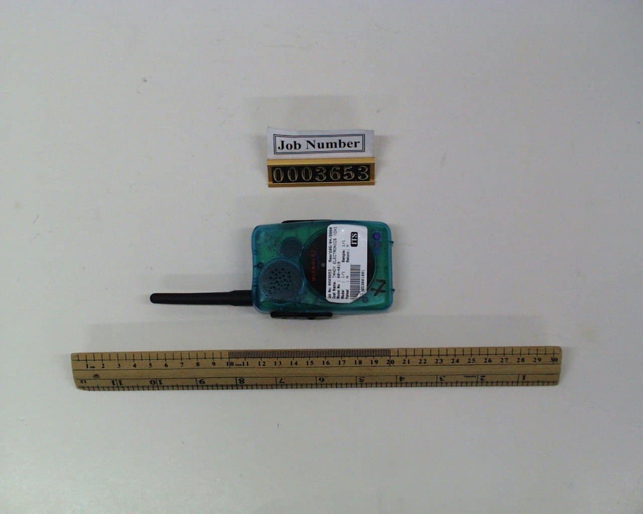
Click to zoom
Application Details
- Equipment Class
- FRF - Part 95 Family Radio Face Held Transmitter
- Date of Grant
- Jun 19, 2000
- Application Purpose
- Original Equipment
- Date of Application
- Jun 19, 2000
- Equipment Note
- Family Radio Service
- Frequency Range
- 462.56250000 - 462.56250000
- Company
- RadioShack Corporation
- Country
- United States
Documents & Files
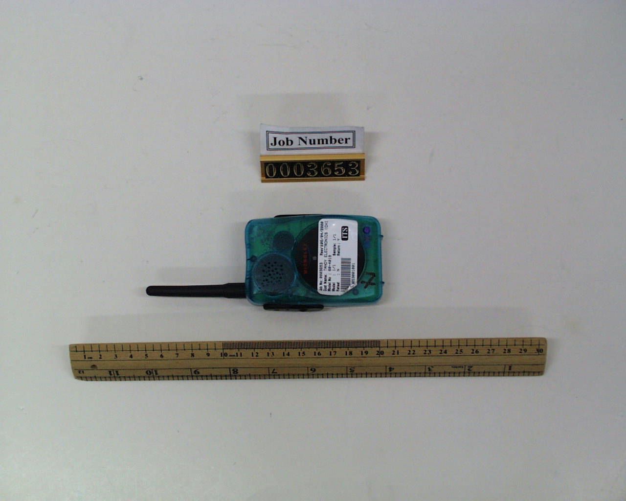
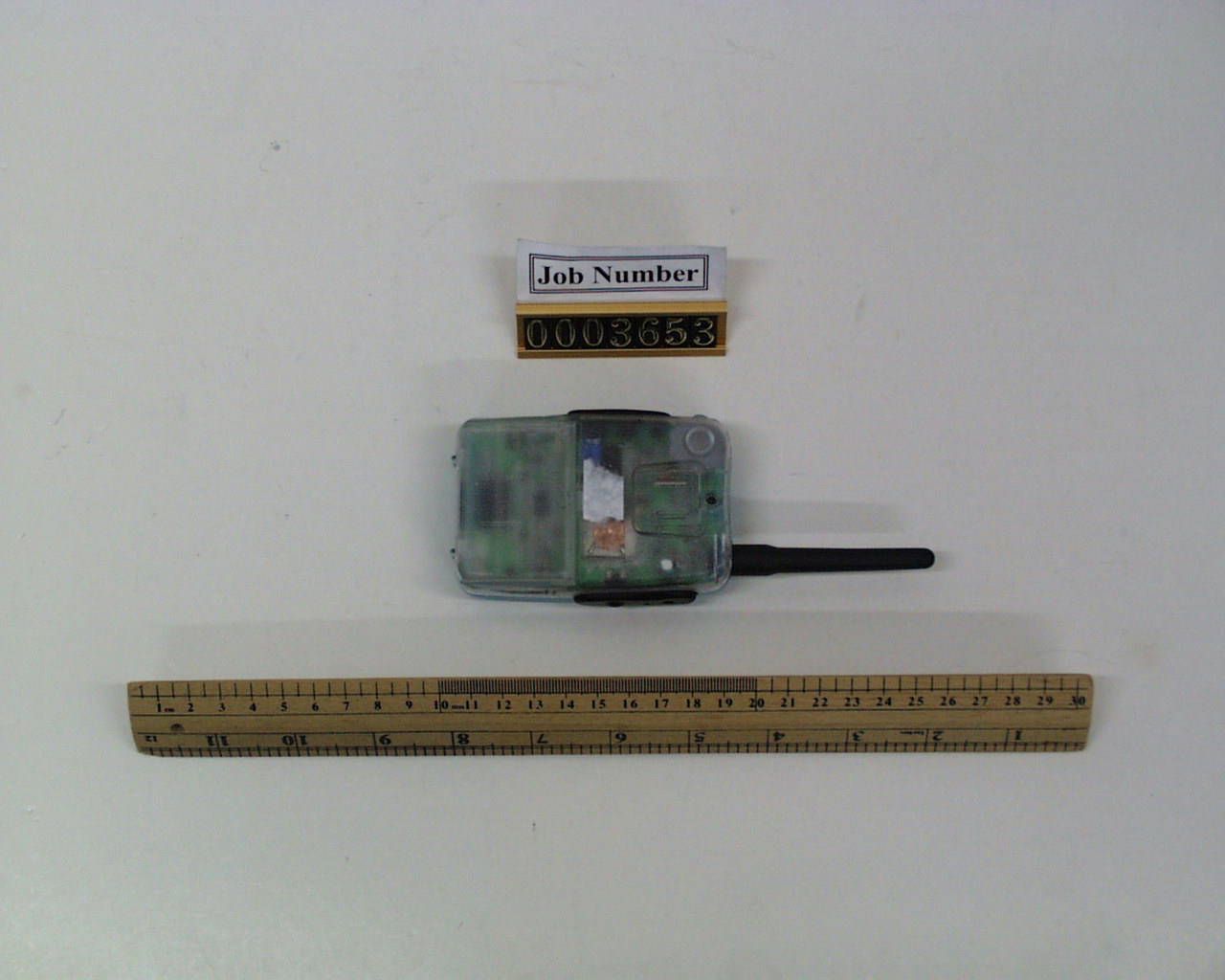
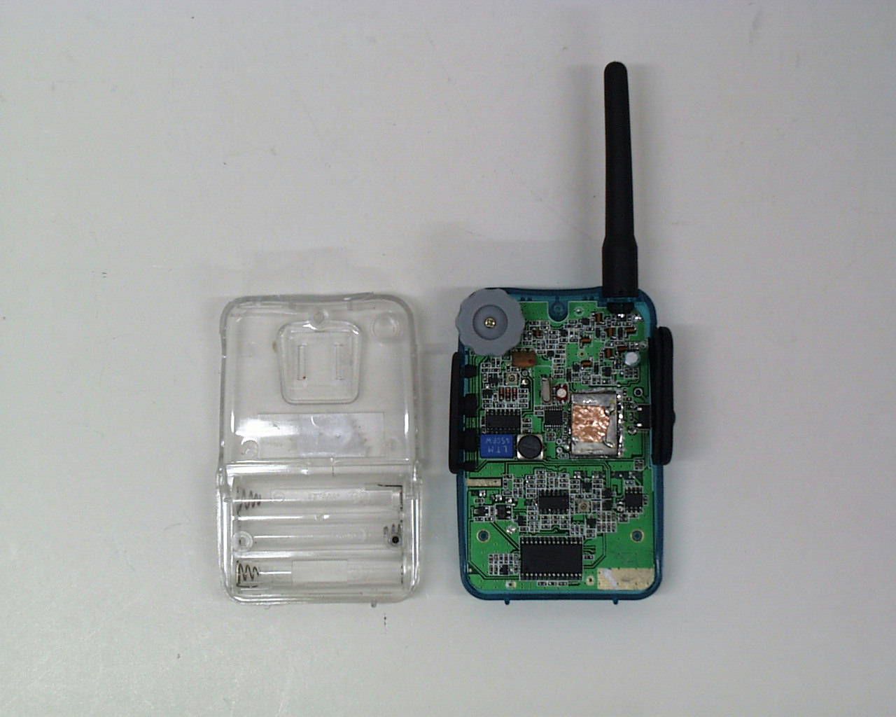
Document Text
Text extracted from the exhibit documents filed with the FCC. Open a document above to read the original.
Parts List/Tune Up Info
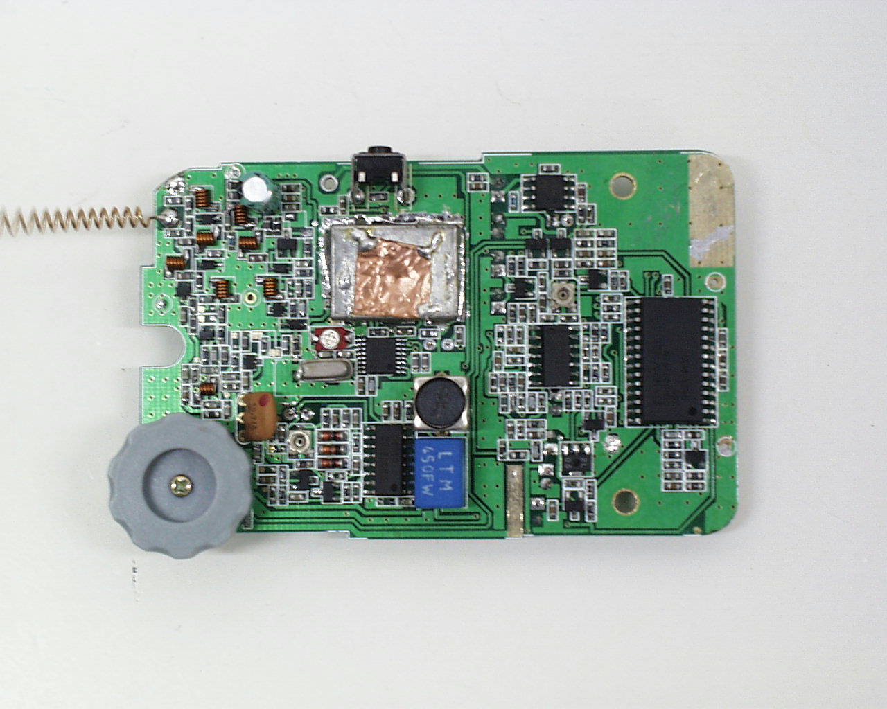
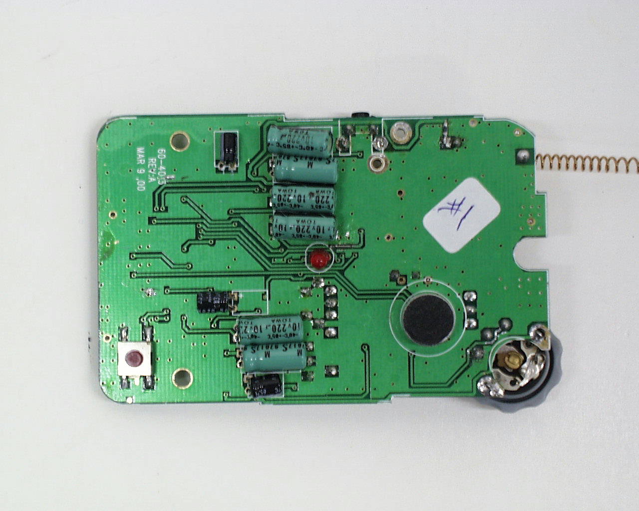
1 Alignment Procedures Both RX and TX sections of 60-4019 need to be aligned for optimum performance. Steps and testing equipment are listed as follows: A: Adjust VCO control voltage VT The LO frequency is mainly controlled by the VD1, C203, L201, C204, C210 and C209, Initially the LO frequency is incorrect. By adjusting the air-coil L201, the LO frequency can be controlled. 1. Press PTT, adjust L201 until the voltage of VT point is 1.4+/- 0.1V. 2. Waxing to L201 and L202 3. Press PTT, slightly adjust L021 until the voltage of VT point is 2.0+/-0.1V. 4. Re-waxing L201. 5. Cover and Solder the VCO shielding case 6. Press PTT, re-check the voltage of VT : it must be 2.0+/-0.3V. Release PTT : it must be >= 0.4V. 7. Cover the hole on the shielding case with the copper – sheet . Tuning component: L201 Equipment:Test jig with pin connected to VT Voltage meter Personnel:Skilful Press PTT B. VCO output frequency and TX power The reference frequency of the PLL is generated by the crystal X1. Since each crystal characteristic has a bit difference. We need to use the variable capacitor VC1 to control the accuracy of the PLL. We need to connect the board ANT output through connector J201 to the spectrum analyser to check the frequency accuracy (=<300Hz) and TX power ( >=15dBm). Tuning component:VC1 Equipment:Spectrum analyser with high stability time base Personnel:Skilful Press PTT C: Quadrature coil tuning During the demodulation process, the audio signal is recovered by the quadrature coil L8. By adjusting the quadrature coil, the audio output with minimum distortion can be obtained. For reference, In MAX volume, adjust L4 get the MAX audio output, then turn the volume to a audio output as 0.6V, slightly adjust L4 to get the MAX audio output. DUT Spectrum analyser or Frequency Counter with accuracy ≤ 1ppm J201 4.5V Power Supply DUT Voltage meter VT 4.5V Power Supply 2 Tuning component : L8 Equipment:Test jig with pin connected to SPK CRO Signal generator w ith output set to the desired channel (w ith 1kHz internal modulation source and 1.5kHz FM deviation). The output level should set to 1mV. Personnel:Non-skilful D: RX sensitivity turning Adjusting L7 has effect on RX sensitivity. Input RF signal –110dBm, adjust L7 to reach the SINAD over 21.5dBm. Tuning component:L7 Equipment:Test jig with pin connected to speaker terminals Signal generator at –110dBm with 1kHz modulation source of 1.5kHz FM deviation. SINAD meter Personnel:Skilful E: Squelch Control tuning The squelch function of 60-4019 function is realised by rectifying the demodulated noise signal. If the rectified noise level is higher than the threshold. A logic level will be generated to the MCU to determine the on and off of speaker. Hence by adjusting the level input to the rectifier, the squelch level can be controlled. 60-4019 needs to adjust VR1 to set to a squelch level of about 12dB audio SINAD at about –120dBm RF input level. In such condition, the speaker should just be fully turned on. Tuning component:Adjust VR1 to reach that the squelch SINAD @threshold is 9-12dB. Equipment:Test jig with pin connected to speaker terminals Signal generator at –120dBm with 1kHz modulation source of 1.5kHz FM deviation. SINAD meter Personnel:Skilful RF Signal Generator DUTSINAD Meter RF Signal Generator Speaker DUT Terminal CRO SPK 4.5V Power Supply J201 J201 RF Signal Generator DUTSINAD Meter 4.5V Power Supply Speaker Terminal J201 3 F : Modulation 60-4019 has its internal build-in amplifier and limiter. Acoustic signal pick up by the microphone will be adjusted to the appropriate signal format before modulating the TX carrier. The FM deviation is required to be limited within 2.5KHz. By adjusting VR2, the FM deviation can then be controlled. Tuning component:VR2 Equipment:Test jig with pin connected to T7 Communication test set or modulation analyser Audio signal generator Personnel:Skilful || Press PTT 4.5V Power Supply Audio Generator 1KH Z @ 100mV T 7 DUTJ201 MODULATION Analyser or Communication test set 4.5 V Power Supply 1 μ F
Test Report
• The test results rep orted in this rep ort shall refer only to the samp le actually tested and shall not refer or be deemed a refer to bulk from which such a samp le may be said to have been obtained. • This rep ort shall not be rep roduced excep t in full without p rior authorization from Intertek Testing Services Hong Kong Limit ed • For Terms And Conditions of the services, it can be p rovided up on request. FCC ID: AAO6004019 Inte rte k Te sting Se rvice s Hong Kong Ltd. 2/F., Garment Centre, 576 Castle Peak Road, Kowloon, Hong Kong. Tel: (852) 2173 8888 Fax: (852) 2745 8306 RadioShack, A Division of Tandy Corp. Application For Certification (FCC ID: AAO6004019) June 12, 2000 WO# 0003653 WN/at June 12, 2000 INTERTEK TESTING SERVICES FCC ID: AAO6004019 i SUMMARY OF CONTENTS LIST OF EXHIBITS EXHIBIT 1 :General Description EXHIBIT 2 :System Test Configuration EXHIBIT 3 :RF Power Output EXHIBIT 4 :Modulation Characteristics EXHIBIT 5 :Occupied Bandwidth EXHIBIT 6 :Emission Spurious EXHIBIT 7 :Frequency Stability EXHIBIT 8 :Technical Specifications EXHIBIT 9 :Product Labelling EXHIBIT 10 :Photographs EXHIBIT 11: Instruction Manual INTERTEK TESTING SERVICES FCC ID: AAO6004019 ii MEASUREMENT/TECHNICAL REPORT Application : RadioShack, A Division of Tandy Corp. Trade Name/Model No : RadioShack 60-4019 Date: May 24, 2000 Sample Receipt Date: June 4, 2000 This report concerns (check one:)Original Grant X Class II Change Equipment Type: Family Radio Service, FRS Deferred grant requested per 47 CFR 0.457(d)(1)(ii)? Yes No X If yes, defer until: date Company Name agrees to notify the Commission by: date of the intended date of announcement of the product so that the grant can be issued on that date. Report prepared by:Wilson Loke Intertek Testing Services. 2/F., Garment Centre, 576 Castle Peak Road, Kowloon, Hong Kong. Phone: 852-2173-8575 Fax:852-2745-8306 INTERTEK TESTING SERVICES FCC ID: AAO6004019 iii Table of Contents 1.0 General Description ................................................................................................................ 2 1.1 Product Description ............................................................................................................2 1.2 Ralated Submittal(s) Grants ................................................................................................ 3 1.3 Test Methodology ...............................................................................................................3 1.4 Test Facility......................................................................................................................... 3 2.0 System Test Configuration ...................................................................................................... 5 2.1 Justification ......................................................................................................................... 5 2.2 EUT Exercising Software .................................................................................................... 6 2.3 Special Accessories .............................................................................................................6 2.4 Equipment Modification ..................................................................................................... 6 3.0 RF Power Output (Section 2.985(a)) ..................................................................................... 8 4.0 Modulation Characteristics (Section 95.637(a)) ................................................................. 12 4.1 Modulation Frequency Response ...................................................................................... 13 4.2 Modulation Limiting Characteristic................................................................................... 15 5.0 Occupied Bandwidth (Section 95.633(c)) ............................................................................ 18 6.0 Spurious Emission (Section 95.635) ..................................................................................... 20 6.1 Field Strength of Spurious Radiation ................................................................................ 21 7.0 Frequency Stability (Section 95.627) ................................................................................... 26 7.1 Frequency Tolerance ......................................................................................................... 27 7.2 Frequency Stability - Temperature.................................................................................... 29 7.3 Frequency Stability - Voltage............................................................................................ 31 8.0 Technical Specifications ........................................................................................................ 34 8.1 Block Diagram................................................................................................................... 35 8.2 Schematic Diagram............................................................................................................ 36 9.0 Product Labelling .................................................................................................................. 38 9.1 Label Artwork & Location ................................................................................................ 39 10.0 Equipment Photographs ..................................................................................................... 41 11.0 Instruction Mannal .............................................................................................................. 43 INTERTEK TESTING SERVICES FCC ID: AAO6004019 iv List of attached file Exhibit typeFile DescriptionFilename Cover LetterLetter of Agencyletter.pdf Operation DescriptionTechnical Descriptiondescri.pdf Test ReportBandwidth Plotbw.pdf Test ReportModulation Frequency Responsemfr.pdf Test ReportModulation Limit Characteristicmlc.pdf Test ReportSpurious Emissionspurious.…
Text truncated - open the document above for the full version.
Contact Information
Applicant
Elizabeth Granados(Regulatory Affairs Manager)
Technical Contact
Intertek Testing Services Hong Kong Ltd.Wilson Loke
[email protected]852-21738575
2/f., Garment Centre, · Kowloon · Hong Kong
Non-Technical Contact
Intertek Testing Services Hong Kong Ltd.Wilson Loke
[email protected],852-21738575
Test Firm
Intertek Testing Services Hong KongBilly Chow
Technical Specifications
| # | Rule Parts | Frequency Range | Power Output | Emission | Tolerance |
|---|---|---|---|---|---|
| 1 | 95B | 462.5625 MHz - 462.5625 MHz | 26.00 mW | 10K0F3E | 0.0002500000 % |
Other Applications from RadioShack Corporation

AAO2302500
Feb 10, 2015Bluetooth Power Bank
Equipment Class
DXX - Part 15 Low Power Communication Device Transmitter
AAO4300124C
May 02, 2013900MHz Wireless Intercom
Equipment Class
DXT - Part 15 Low Power Transceiver, Rx Verified
AAO1200876
Nov 30, 2011Universal FM Transmitter
Equipment Class
DXX - Part 15 Low Power Communication Device Transmitter
AAO1200962
Aug 02, 2011Universal FM Transmitter
Equipment Class
DXX - Part 15 Low Power Communication Device Transmitter
AAO1500044T
Apr 02, 20112.4GHz Digital Wireless Rear Speaker Kit - Transmitter
Equipment Class
DSS - Part 15 Spread Spectrum Transmitter