AAO6301123Remote Door Bell (Receiver)
RadioShack Corporation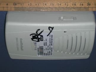
Click to zoom
Application Details
- Equipment Class
- CRR - Superregenerative Receiver
- Date of Grant
- Jun 30, 2002
- Application Purpose
- Original Equipment
- Date of Application
- Jun 30, 2002
- Equipment Note
- Remote Door Bell (Receiver)
- Frequency Range
- 433.92000000 - 433.92000000
- Company
- RadioShack Corporation
- Country
- United States
Documents & Files
Document Text
Text extracted from the exhibit documents filed with the FCC. Open a document above to read the original.
Users Manual
© 2002 RadioShack Corporation. All Rights Reserved. RadioShack and RadioShack.com are trademarks used by RadioShack Corporation. 63-1123OWNER’S MANUAL — Please read before using this equipment. Thank you for purchasing the RadioShack Single Bell Wireless Door Chime. It works as a doorbell, remote pager, or an alert. You can add an optional external sensor to have a chime that alerts you when someone walks into a room. The door chime’s three- position channel switch helps prevent other transmitters or radio devices from sounding the chime. /1706+0)"6*'" 64#05/+66'4" 1. Remove the transmitter from the holder. 2. Use the holder as a template to mark two screw holes on the wall. 3. Remove the holder from the mounting surface and drill two 3 / 16 inch diameter holes. Insert one of the supplied anchors into each hole. 4. Drive a screw through the holder into each hole. 5. The transmitter can be slid in and out of the holder. To lock the transmitter, fix it with a size M2.6 screw at the bottom of the holder. +056#..+0)" $#66'4+'5"#0&" 5'.'%6+0)"%*#00'.5 The door chime requires three AAA batteries in the transmitter and three C batteries in the receiver. For best performance and longest life, we recommend RadioShack alkaline batteries. . .. . +0"6*'"64#05/+66'4 1. Slide the transmitter's battery compartment door in the direction of the arrow to remove it. 2. Use a small flat-blade screwdriver to slide the switch inside the battery compartment to the desired channel for the transmitter. 3. Install three AAA batteries as indicated by the polarity symbols (+ and –) marked inside. 4. Replace the compartment door. If the transmitter's LED indicator dims, replace the batteries. +0"6*'"4'%'+8'4 1. Slide the receiver's battery compartment door in the direction of the arrow to remove it. 2. Slide the switch inside the battery compartment to select the same channel for the receiver as is selected for the transmitter. ± 3. Install three C batteries as indicated by the polarity symbols (+ and –) marked inside. 4. Replace the compartment door. If the receiver's LED flashes with a short beep tone, replace its batteries. # "+/2146#06" # If an icon appears at the end of a paragraph, go to the box on that page with the corresponding icon for pertinent information. R ̋ — Warning ∞ ∞∞ ∞ — Hint . .. . — Caution ± — Note # — Important Receiver Transmitter Slide ON/OFF to ON so that when BELL is pressed on the transmitter, a door chime sounds. BELL — Press BELL to hear the door chime. Indicator — Lights when BELL is pressed. . "%#76+10" . • Use only fresh batteries of the required size and type. Always remove old or weak batteries. They can leak chemicals that destroy electronic circuits • Do not mix old and new batteries, different types of batteries (standard, alkaline, or rechargeable), or rechargeable batteries of different capacities. . "%#76+10" . • Use only fresh batteries of the required size and type. Always remove old or weak batteries. They can leak chemicals that destroy electronic circuits • Do not mix old and new batteries, different types of batteries (standard, alkaline, or rechargeable), or rechargeable batteries of different capacities. ±"016'"±" The channel settings must be the same for the transmitter and the receiver. If the door chime occasionally sounds without anyone pressing BELL, change the channel settings for both the transmitter and receiver. 5KPING"$GNN"9KTGNGUU"&QQT"%JKOG 63-1123.fm Page 1 Thursday, June 6, 2002 12:41 PM 63-1123 AO0113AAA1 06A02 Printed in China RadioShack Corporation Fort Worth, Texas 76102 12'4#6+10 Slide ON/OFF on the receiver to ON . When BELL is pressed on the transmitter, the transmitter’s indicator lights and the door chime sounds. ± ':6'40#."5'0514" There are two holes on the back of the transmitter that can be used to connect an optional external sensor (avilable at your local RadioShack store). 6*'"(%%"9#065";17" 61"-019 This equipment has been tested and found to comply with the limits for a Class B digital device, pursuant to Part 15 of the FCC Rules . These limits are designed to provide reasonable protection against harmful interference in a residential installation. This equipment generates, uses and can radiate radio frequency energy and, if not installed and used in accordance with the instructions, may cause harmful interference to radio communications. However, there is no guarantee that interference will not occur in a particular installation. If this equipment does cause harmful interference to radio or television reception, which can be determined by turning the equipment off and on, the user is encouraged to try to correct the interference by one or more of the following measures: • Reorient or relocate the receiving antenna. • Increase the separation between the equipment and receiver. • Consult your local RadioShack store or an experienced radio/TV technician for help. • If you cannot eliminate the interference, the FCC requires that you stop using your door chime. Changes or modifications not expressly approved by RadioShack may cause interference and void the user’s authority to operate the equipment. 52'%+(+%#6+105 Frequency ........................ 433.92 MHz ± 600KHz Transmitter current consumption............... <10mA Receiver current consumption...<2mA @ standby < 85mA @ sound playing Receiver battery low.......................... 2.4V ± 0.1V Receiver audio power............... > 80dBA @ 25cm Transmitter operating temperature ..................................–20 ° C to 60 ° C (–4 ° F to 140 ° F) Specifications are typical; individual units might vary. Specifications are subject to change without notice. ±"016'"±" •Press BELL until the transmitter’s indicator lights. Otherwise, the receiver may not work properly. • If you don't want to hear the door chime, slide ON/OFF on the receiver to OFF. Limited One-Year Warranty This product is warranted by RadioShack against manufacturing defects in material and workman- ship under normal use for o…
Text truncated - open the document above for the full version.
External Photos
Test SetupFCCID : AAO6301123 Model : 63-1123 External Photo -front External Photo - rear Test SetupFCCID : AAO6301123 Model : 63-1124 External Photo –front External Photo –rear
Internal Photos
Test SetupFCCID : AAO6301123 Model : 63-1123 Internal Photo - 1 Internal Photo - 2 Test SetupFCCID : AAO6301123 Model : 63-1123 Internal Photo – 3 Internal Photo - 4 Test SetupFCCID : AAO6301123 Model : 63-1124 Internal Photo – 1 Internal Photo – 2 Test SetupFCCID : AAO6301123 Model : 63-1124 Internal Photo – 3 Internal Photo – 4
Operational Description
63-1123 Circuit Theory Receiver The receiver is a super-regenerative receiver. The pre-amplifier formed by Q1 amplified the received RF signal from the antenna. The amplified signal is then being fed to the super-regenerative circuit formed by Q2. The frequency of the super-generative circuit can be adjusted by tuning the variable capacitor VC1. The received RF signal is demodulated by the super-regenerative circuit and then being fed to the data amplifiers which consist of Q3, Q4 and Q5. The demodulated data is amplified by the data amplifiers and then being to the MCU (pin 10 of U1). Once the MCU decoded the received data, it will send a door chime to the audio amplifier Q8. There is a low battery circuit formed by Q13 to detect the battery voltage. The low battery level can be adjusted by tuning variable resistor VR1. The factory setting was at 2.4V. There is a 3V regulator (U2) that provides stable supply voltage to MCU control circuit. 63-1124 Circuit Theory Receiver The receiver is a super-regenerative receiver. The pre-amplifier formed by Q1 amplified the received RF signal from the antenna. The amplified signal is then being fed to the super-regenerative circuit formed by Q2. The frequency of the super-generative circuit can be adjusted by tuning the variable capacitor VC1. The received RF signal is demodulated by the super-regenerative circuit and then being fed to the data amplifiers which consist of Q3, Q4 and Q5. The demodulated data is amplified by the data amplifiers and then being to the MCU (pin 10 of U1). Once the MCU decoded the received data, it will either send a door chime to the audio amplifier Q8 or enable music IC (U4) by apply a logic zero to pin 16 of U1. When Q7 is turned on by the MCU, U4 is powered by Q7 and then send out a song to audio buffer amplifier formed by Q12. At the same time, the power switch formed by Q10 and Q9 is also turned on to enable the audio amplifier Q8. Therefore, either the door chime from the MCU or music from the music IC can be applied to the speaker. There is a low battery circuit formed by Q13 to detect the battery voltage. The low battery level can be adjusted by tuning variable resistor VR1. The factory setting was at 2.4V. There is a 3V regulator (U2) that provides stable supply voltage to MCU control circuit.
Test Report
• The test results reported in this test report shall refer only to the sample actually tested and shall not refer or be deemed to refer to bulk from which such a sample may be said to have been obtained. • This report shall not be reproduced except in full without prior authorization from Intertek Testing Services Hong Kong Limited Intertek Testing Services Hong Kong Ltd. 2/F., Garment Centre, 576 Castle Peak Road, Kowloon, Hong Kong. Tel: (852) 2173 8888 Fax: (852) 2745 8306 RadioShack Corporation Application For Certification (FCC ID: AAO6301123) Superregenerative Receiver WO# 0206163 WL/Sandy June 14, 2002 INTERTEK TESTING SERVICES FCC ID: AAO6301123 i LIST OF EXHIBITS INTRODUCTION EXHIBIT 1:General Description EXHIBIT 2:System Test Configuration EXHIBIT 3:Emission Results EXHIBIT 4:Equipment Photographs EXHIBIT 5:Product Labelling EXHIBIT 6:Technical Specifications EXHIBIT 7:Instruction Manual EXHIBIT 8:Miscellaneous Information INTERTEK TESTING SERVICES FCC ID: AAO6301123 ii MEASUREMENT/TECHNICAL REPORT RadioShack Corporation - MODEL:RadioShack 63-1124 RadioShack 63-1123 FCC ID: AAO6301123 This report concerns (check one:)Original Grant X Class II Change _____ Equipment Type: Superregenerative Receiver (example: computer, printer, modem, etc.) Deferred grant requested per 47 CFR 0.457(d)(1)(ii)?Yes No X If yes, defer until: date Company Name agrees to notify the Commission by: date of the intended date of announcement of the product so that the grant can be issued on that date. Transition Rules Request per 15.37?Yes No X If no, assumed Part 15, Subpart B for unintentional radiator - the new 47 CFR [12-18-01 Edition] provision. Report prepared by:Wilson Loke Intertek Testing Services Hong Kong Ltd. 2/F., Garment Centre, 576, Castle Peak Road, Kowloon, Hong Kong. Phone:852-2173-8575 Fax:852-2371-0521 INTERTEK TESTING SERVICES FCC ID: AAO6301123 iii Table of Contents 1.0 General Description............................................................................................................2 1.1 Product Description............................................................................................................2 1.2 Related Submittal(s) Grants.................................................................................................2 1.3 Test Methodology...............................................................................................................3 1.4 Test Facility........................................................................................................................3 2.0 System Test Configuration.................................................................................................5 2.1 Justification.........................................................................................................................5 2.2 EUT Exercising Software....................................................................................................5 2.3 Special Accessories..............................................................................................................5 2.4 Equipment Modification......................................................................................................6 2.5 Measurement Uncertainty......................................................................................................6 2.6 Support Equipment List and Description..................................................................................6 3.0 Emission Results.................................................................................................................8 3.1 Field Strength Calculation....................................................................................................9 3.2 Radiated Emission Configuration Photograph.....................................................................10 3.3 Radiated Emission Data....................................................................................................11 4.0 Equipment Photographs....................................................................................................14 5.0 Product Labelling..............................................................................................................16 6.0 Technical Specifications....................................................................................................18 7.0 Instruction Manual............................................................................................................20 8.0 Miscellaneous Information...............................................................................................22 8.1 Stabilization Waveform.....................................................................................................23 8.2 Discussion of Pulse Desensitization....................................................................................24 8.3 Calculation of Average Factor...........................................................................................25 8.4 Emissions Test Procedures................................................................................................26 INTERTEK TESTING SERVICES FCC ID: AAO6301123 iv List of attached file Exhibit typeFile Descriptionfilename Test ReportTest Reportreport.pdf Operation DescriptionTechnical Descriptiondescri.pdf Test Setup PhotoRadiated Emissionradiated photos.doc External PhotoExternal Photoexternal photos.doc Internal PhotoInternal Photointernal photos.doc Block DiagramBlock Diagramblock.pdf SchematicsCircuit Diagramcircuit.pdf ID Label/LocationLabel Artwork and Locationlabel.pdf User ManualUser Manualmanual.pdf Test ReportStabilization Waveformsuperreg.pdf INTERTEK TESTING SERVICES FCC ID: AAO6301123 1 EXHIBIT 1 GENERAL DESCRIPTION INTERTEK TESTING SERVICES FCC ID: AAO6301123 2 1.0General Description 1.1Product Description The Equipment Under Test (EUT) is a Receiver operating at 433.92MHz. The EUT is powered by 4.5V d.c. (3 x 1.5V “C” …
Text truncated - open the document above for the full version.
Test Setup Photos
Test SetupFCCID : AAO6301123 Radiated -front Radiated - rear
Contact Information
Applicant
Elizabeth Granados(Regulatory Affairs Manager)
Technical Contact
Intertek Testing Services Hong Kong Ltd.Wilson Loke
[email protected]852 2173 8575
2/F, Garment Centre · Kowloon · Hong Kong
Non-Technical Contact
Intertek Testing Services Hong Kong Ltd.Wilson Loke
[email protected]852 2173 8575
Test Firm
Intertek Testing Services Hong KongBilly Chow
Technical Specifications
| # | Rule Parts | Frequency Range | Power Output |
|---|---|---|---|
| 1 | 15B | 433.92 MHz - 433.92 MHz | - |
Other Applications from RadioShack Corporation

AAO2302500
Feb 10, 2015Bluetooth Power Bank
Equipment Class
DXX - Part 15 Low Power Communication Device Transmitter
AAO4300124C
May 02, 2013900MHz Wireless Intercom
Equipment Class
DXT - Part 15 Low Power Transceiver, Rx Verified
AAO1200876
Nov 30, 2011Universal FM Transmitter
Equipment Class
DXX - Part 15 Low Power Communication Device Transmitter
AAO1200962
Aug 02, 2011Universal FM Transmitter
Equipment Class
DXX - Part 15 Low Power Communication Device Transmitter
AAO1500044T
Apr 02, 20112.4GHz Digital Wireless Rear Speaker Kit - Transmitter
Equipment Class
DSS - Part 15 Spread Spectrum Transmitter