AAOAWS1475T900MHz Wireless Speaker
RadioShack Corporation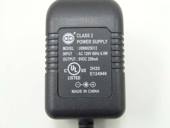
Click to zoom
Application Details
- Equipment Class
- DXX - Part 15 Low Power Communication Device Transmitter
- Date of Grant
- Dec 27, 2005
- Application Purpose
- Original Equipment
- Date of Application
- Dec 27, 2005
- Equipment Note
- 900MHz Wireless Speaker
- Frequency Range
- 915.60000000 - 918.40000000
- Company
- RadioShack Corporation
- Country
- United States
Documents & Files
Document Text
Text extracted from the exhibit documents filed with the FCC. Open a document above to read the original.
Users Manual
Please read this user’s guide before installing, setting up, or using your new product. AWS-1475 900MHz Wireless Indoor /Outdoor Mnon Speaker Thank you for purchasing your Accurian 900MHz Wireless Indoor/Outdoor Mono Speaker. speaker transmitter 12V DC adaptor 9V DC adaptor RCA cable 3.5mm plug adaptor 6.3mm plug adaptor user’s guide what’s included Connect the 9V DC adaptor to the transmitter’s DC jack, then plug the other end into a standard AC outlet. powering the transmitter Each transmitter has three channels, select the desired channel to match the receiver’s channel. Make sure that the transmitter’s channel is the same as the receiver’s channel. setting the channel FCC Information This equipment has been tested and found to comply with the limits for a Class B digital device, pursuant to Part 15 of the FCC Rules. These limits are designed to provide reasonable protection against harmful interference in a residential installation. This equipment generates, uses, and can radiate radio frequency energy and, if not installed and used in accordance with the instructions, may cause harmful interference to radio communications. However, there is no guarantee that interference will not occur in a particular installation. If this equipment does cause harmful interference to radio or television reception, which can be determined by turning the equipment off and on, the user is encouraged to try to correct the interference by one or more of the following measures: • Reorient or relocate the receiving antenna. • Increase the separation between the equipment and receiver. • Connect the equipment into an outlet on a circuit different from that to which the receiver is connected. Consult your local RadioShack store or an experienced radio/TV technician for help. If you cannot eliminate the interference, the FCC requires that you stop using your speaker. Changes or modifications not expressly approved by RadioShack may cause interference and void the user’s authority to operate the equipment. This device complies with Part 15 of the FCC Rules. Operation is subject to the following two conditions: (1) This device may not cause harmful interference, and (2) This device must accept any interference received, including interference that may cause undesired operation. speaker transmitter G -VOLUME Rotate in the direction of the arrow until it clicks to turn on the speaker. The green led lights. Then adjust it to a comfortable listening level. To turn off, rotate it clockwise until it clicks. BASS To increase or decrease bass notes. Transmitter Carrier Frequency ................................................................................915.6 - 918.4 MHz Power Source ........................................................................................................................... Unregulated 9V DC, Center Tip set to positive (+), 250mA Modulation Method ................................................................................FM Modulation Frequency Response .................................................................... 80 Hz – 20 kHz (6 dB) Measurement (WHD) ................................................................4½ x 2½ x 41/8 Inches Speaker Power Source .............................................................................................................12V DC Sensitivity .....................................................................................< 2μV (with 20 dB S/N) S/N Radio (@-50 dBm) ..........................................................................70 dB (A weight) Audio Distortion ............................................................................................................ <2% Max. Audio output ..................................................................................................... >=5W Measurement (WHD) ................................................................. 82/3 x 11 x 8¼ Inches Specifications are typical; individual units might vary. Specifications are subject to change and improvement without notice. Actual product may vary from the product images in this document. specifications NOTE channel 39V DC adaptor DC 9V jack Caution: Do not attempt to recharge alkaline batteries or regular batteries. Warning: Do no try to recharge the non-rechargeable batteries, or the batteries would explode! The speakers’ DC 12V jack is for charging rechargeable batteries and powering the speaker. 1. Turn off the speaker. 2. Remove the battery cover. 3. Slide ON/OFF inside the battery compartment to ON. 4. Insert eight C rechargeable batteries in the battery compartment, matching the polarity symbols (+ and -) marked inside. 5. Connect one end of the 12V DC adaptor to the DC 12V jack and plug the other end to a standard AC outlet. 6. When charging is completed, unplug the DC adaptor from the power source, and disconnect it form the speaker’s DC jack. recharging Ni-Cd or Ni-MH batteries transmitterspeaker You can connect your audio source (such as MP3, CD and DVD) to the transmitter with the supplied RCA cable. 1. Connect the RCA cable’s color jacks to your transmitter by matching the color. 2. Plug the other ends into your audio source’s output jacks. If the output jack of your audio source is 3.5mm or 6.3mm, connect the RCA cable to the 3.5mm plug adaptor or/and 6.3mm plug adapter for the connection. connecting to y0ur audio source You can power the speaker with the 12V DC adaptor. To power the speaker with AC power, connect one end of the 12V DC adapter to the receiver, then plug the other end into a standard AC outlet. The green led on the transmitter turns on when its built- in Automatic Level Detection circuit detects the music or signal from the audio source. When the audio source stops for more than 30 seconds, the transmitter will automatically shut down and enter the standby mode. powering the speaker with AC power 1. Lift up the battery cover on the bottom of the speaker. 2. If the batteries are non-recharg…
Text truncated - open the document above for the full version.
Block Diagram
Block Diagram for 40-1475 900MHz Indoor /Outdoor Mono Speaker (transmitter) Addy 10/24/05 TES revision B Compresso r Left Right BUF VCO BUF PA A ntenna PLL Crystal16MHz MCU uPD64A-888 VOX detect 1 p in 3 p ins PLL &control Resonator 4MHz 3 p ins Regulator & Power control 1 p in Code Selector:S1 short to ground fortransmitte r 1 p in 915.6MHz to918.4MHz S1T8825B01 GL6552 Q5 &Q7 Audio-in 12 Channel Selecto r 3 DC Socket 3.6V 5V
External Photos
INTERTEK TESTING SERVICE Report No.: 05218352 FCC ID: AAOAWS1475T Equipment Photographs Model : AWS-1475 (External) INTERTEK TESTING SERVICE Report No.: 05218352 FCC ID: AAOAWS1475T Equipment Photographs Model : AWS-1475 (External) INTERTEK TESTING SERVICE Report No.: 05218352 FCC ID: AAOAWS1475T Equipment Photographs Model : AWS-1475 (External)
ID Label/Location Info
Size: 35x60 mm ART NO. REV ECN NO. MODLE ZONE DESCRIPTION DRAFTDATE A PART NO. DWG. NO. PART NAME DEST APPROVED CHECKED DRAFT PLS RETURN IMMEDIATELY AFT FILMED SCALE AWS-1475 U.S.A Rating Label-TX Merry 1:1 generated label A/W Merry DATE 10/13/05 TANDY RADIOSHACK LIMITED A Division of RadioShack Corporation 10/13/05 Rating label Date code label 900MHz Wireless Indoor/Outdoor Mono Speaker This device complies with Part 15 of the FCC Rules. Operation is subject to the following two conditions: (1) this device may not cause harmful interference, and (2) this device must accept any interference received, including interference that may cause undesired operation. Power: 9VDC, 250mA, Plug Type "M” FCC ID: AAOAWS1475T Model No. AWS-1475 Manufactured in China for Innovation One, Inc., 350 N. Henderson St., Ft. Worth, TX 76102 Rating label L01475P02A TM AL1279AAA1 F10623A
Internal Photos
INTERTEK TESTING SERVICE Report No.: 05218352 FCC ID: AAOAWS1475T Equipment Photographs Model : AWS-1475 (Internal) INTERTEK TESTING SERVICE Report No.: 05218352 FCC ID: AAOAWS1475T Equipment Photographs Model : AWS-1475 (Internal) INTERTEK TESTING SERVICE Report No.: 05218352 FCC ID: AAOAWS1475T Equipment Photographs Model : AWS-1475 (Internal) INTERTEK TESTING SERVICE Report No.: 05218352 FCC ID: AAOAWS1475T Equipment Photographs Model : AWS-1475 (Internal)
Operational Description
Circuit Description of 40-1475 900MHz Wireless Indoor/Outdoor Mono Speaker Issued by: Addy 09/26/05Revision APage 2 of 10 TRANSMIT SECTION Compressor The audio signal from RCA jack (JK1 & JK2) feeds to the compressor U1. After the audio signal has been compressed, it delivers to the buffer amplifier (Q6) and pre-emphasis by a RC network (C2, R24 and R25). Then, the signal is routed to the voltage control oscillator (VCO) section. Auto Level Control (ALC) To prevent the transmitter from over-modulation, U1 provided a built-in ALC circuitry. The ALC attack time and recovery time is control by C6. The ALC starting point is controlled by the potential divider R1 and R2. VOX detection To detect if there is any signal presenting at the input terminal for the transmitting purpose, a VOX detection circuitry is built with Q5 and Q7. It amplifies the signal from the compressor output (pin 12) and direct feeds to the pin 11 of the MCU. When there is signal presenting at pin 11 of the MCU, it’s output pin 20 goes high. It turns on the power supply of the RF transmitter section. After that it polls the data to the phase lock loop (PLL) IC U401 and starts the transmission. Oscillator and Modulator The oscillation frequency is derived from a single 16MHz crystal by means of a phase locked loop (PLL). The voltage control oscillator (VCO) is formed by Q404; L404 and D401.Frequency modulation is provided by a varactor diode VD401 when the audio signal is applied through the resistor R460. RF Power Amplifier and switching circuitry Q405 and Q406 are adopted as the power amplifier to drive the antenna through the low pass filter (L401, L402, C402, C403 and C450).
Test Report
• The test results reported in this test report shall refer only to the sample actually tested and shall not refer or be deemed to refer to bulk from which such a sample may be said to have been obtained. • This report shall not be reproduced except in full without prior authorization from Intertek Testing Services Hong Kong Limited • For Terms And Conditions of the services, it can be provided upon request. • The evaluation data of the report will be kept for 3 years from the date of issuance. Intertek Testing Services Hong Kong Ltd. 2/F., Garment Centre, 576 Castle Peak Road, Kowloon, Hong Kong. Tel: (852) 2173 8888 Fax: (852) 2785 5487 Website: www.hk.intertek-etlsemko.com RadioShack Corporation Application For Certification (FCC ID: AAOAWS1475T) Transmitter 05218352 LC/el December 14, 2005 INTERTEK TESTING SERVICES FCC ID: AAOAWS1475T i LIST OF EXHIBITS INTRODUCTION EXHIBIT 1: General Description EXHIBIT 2 : System Test Configuration EXHIBIT 3: Emission Results EXHIBIT 4: Equipment Photographs EXHIBIT 5: Product Labelling EXHIBIT 6: Technical Specifications EXHIBIT 7: Instruction Manual EXHIBIT 8: Miscellaneous Information INTERTEK TESTING SERVICES FCC ID: AAOAWS1475T ii MEASUREMENT / TECHNICAL REPORT RadioShack Corporation − MODEL: AWS-1475 FCC ID: AAOAWS1475T December 14, 2005 This report concerns (check one:) Original Grant X Class II Change Equipment Type: Low Power Transmitter (example: computer, printer, modem, etc.) Deferred grant requested per 47 CFR 0.457(d)(1)(ii)? Yes No X If yes, defer until: date Company Name agrees to notify the Commission by: date of the intended date of announcement of the product so that the grant can be issued on that date. Transition Rules Request per 15.37? Yes No X If no, assumed Part 15, Subpart C for intentional radiator − the new 47 CFR [10-01-04 Edition] provision. Report prepared by: Alfred Lo Intertek Testing Services 2/F., Garment Center, 576 Castle Peak Road, Kowloon, Hong Kong. Phone: 852-2173-8545 Fax: 852-2371-0914 INTERTEK TESTING SERVICES FCC ID: AAOAWS1475T iii Table of Contents 1.0 General Description ..........................................................................................2 1.1 Product Description.....................................................................................2 1.2 Related Submittal(s) Grants .......................................................................2 1.3 Test Methodology .......................................................................................3 1.4 Test Facility .................................................................................................3 2.0 System Test Configuration...............................................................................5 2.1 Justification .................................................................................................5 2.2 EUT Exercising Software ............................................................................5 2.3 Special Accessories....................................................................................5 2.4 Equipment Modification ..............................................................................6 2.5 Measurement Uncertainty...........................................................................6 2.6 Support Equipment List and Description ....................................................6 3.0 Emission Results...............................................................................................8 3.1 Field Strength Calculation...........................................................................9 3.2 Radiated Emission Configuration Photograph .........................................11 3.3 Radiated Emission Data ...........................................................................12 3.4 Conducted Emission Configuration Photograph ......................................14 3.5 Conducted Emission Data ........................................................................15 4.0 Equipment Photographs.................................................................................17 5.0 Product Labelling............................................................................................19 6.0 Technical Specifications.................................................................................21 7.0 Instruction Manual ...........................................................................................23 8.0 Miscellaneous Information .............................................................................25 8.1 Measured Bandwidth ................................................................................26 8.2 Discussion of Pulse Desensitization .........................................................27 8.3 Calculation of Average Factor ..................................................................28 8.4 Emissions Test Procedures ......................................................................29 INTERTEK TESTING SERVICES FCC ID: AAOAWS1475T iv List of attached file Exhibit Type File Description Filename Test Report Test Report report.pdf Operation Description Technical Description descri.pdf Test Setup Photo Radiated Emission radiated photos.pdf Test Setup Photo Conducted Emission conducted photos.pdf Test Report Conducted Emission Test Result conducted.pdf Test Report Bandwidth Plot bw.pdf External Photo External Photo external photos.pdf Internal Photo Internal Photo internal photos.pdf Block Diagram Block Diagram block.pdf Schematics Circuit Diagram circuit.pdf ID Label / Location Label Artwork and Location label.pdf User Manual User Manual manual.pdf INTERTEK TESTING SERVICES FCC ID: AAOAWS1475T 1 EXHIBIT 1 GENERAL DESCRIPTION INTERTEK TESTING SERVICES FCC ID: AAOAWS1475T 2 1.0 General Description 1.1 Product Description The Equipment Under Test (EUT) is a 900MHz wireless transmitter for it corresponding speaker. Transmitter carriers are generated by the VCO & PLL and it is modulated by the compressed audi…
Text truncated - open the document above for the full version.
Test Report
Band edge plot Report: 05218352 Channel 1 Channel 3 FCC ID: AAOAWS1475T Band edge plot Report: 05218352 Channel 1 Channel 3 FCC ID: AAOAWS1475T
Test Report
Report No.: 05218352 Transmitting mode (Channel 1) Ctrl No.: PAGE 1 Tested By:Hong, Report No.:0521835 Scan Settings (1 Range) |--------- Frequencies -----------||----------- Receiver Settings ------------| Start Stop Step IF BW Detector M-Time Atten Preamp OpRge 150k 30M 5k 10k PK+AV 10ms AUTO LN OFF 60dB Final Measurement: x QP / + AV Meas Time: 1 s Subranges: 16 Acc Margin: 20dB Transducer No. Start Stop Name 21 9k 30M EW0698 0 10 20 30 40 50 60 70 80 90 dBuV 100 0.15 MHz 30 110 F15Q F15A NA FCC ID: AAOAWS1475T Report No.: 05218352 Transmitting mode (Channel 1) Ctrl No.: NA FCC ID: AAOAWS1475T Tested By:Hong, Report No.:0521835 Scan Settings (1 Range) |--------- Frequencies -----------||----------- Receiver Settings ------------| Start Stop Step IF BW Detector M-Time Atten Preamp OpRge 150k 30M 5k 10k PK+AV 10ms AUTO LN OFF 60dB Final Measurement Results: no Results Report No.: 05218352 Transmitting mode (Channel 3) Ctrl No.: PAGE 1 Tested By:Hong, Report No.:0521835 Scan Settings (1 Range) |--------- Frequencies -----------||----------- Receiver Settings ------------| Start Stop Step IF BW Detector M-Time Atten Preamp OpRge 150k 30M 5k 10k PK+AV 10ms AUTO LN OFF 60dB Final Measurement: x QP / + AV Meas Time: 1 s Subranges: 16 Acc Margin: 20dB Transducer No. Start Stop Name 21 9k 30M EW0698 0 10 20 30 40 50 60 70 80 90 dBuV 100 0.15 MHz 30 110 F15Q F15A NA FCC ID: AAOAWS1475T Report No.: 05218352 Transmitting mode (Channel 3) Ctrl No.: NA FCC ID: AAOAWS1475T Tested By:Hong, Report No.:0521835 Scan Settings (1 Range) |--------- Frequencies -----------||----------- Receiver Settings ------------| Start Stop Step IF BW Detector M-Time Atten Preamp OpRge 150k 30M 5k 10k PK+AV 10ms AUTO LN OFF 60dB Final Measurement Results: no Results
Test Setup Photos
INTERTEK TESTING SERVICE Report No:05218352 Configuration Photographs Worst-Case Radiated Emissions (Front View) Model : AWS-1475 Fig.1 FCC ID: AAOAWS1475T INTERTEK TESTING SERVICE Report No:05218352 Configuration Photographs Worst-Case Radiated Emissions (Back View) Model : AWS-1475 Fig.2 FCC ID: AAOAWS1475T
Test Setup Photos
INTERTEK TESTING SERVICE Report No.: 05218352 FCC ID: AAOAWS1475T Equipment Photographs Model : AWS-1475 (External) INTERTEK TESTING SERVICE Report No.: 05218352 FCC ID: AAOAWS1475T Equipment Photographs Model : AWS-1475 (External) INTERTEK TESTING SERVICE Report No.: 05218352 FCC ID: AAOAWS1475T Equipment Photographs Model : AWS-1475 (External)
Contact Information
Applicant
Elizabeth Granados(Regulatory Affairs Manager)
Technical Contact
Intertek Testing Services Hong Kong Ltd.Alfred Lo
[email protected]852-2173-8545
2/F., Garment Centre, · Kowloon · Hong Kong
Non-Technical Contact
Intertek Testing Services Hong Kong Ltd.Alfred Lo
[email protected]852-2173-8545
Test Firm
Intertek Testing Services Hong KongBilly Chow
Technical Specifications
| # | Rule Parts | Frequency Range | Power Output |
|---|---|---|---|
| 1 | 15C | 915.6 MHz - 918.4 MHz | - |
Other Applications from RadioShack Corporation

AAO2302500
Feb 10, 2015Bluetooth Power Bank
Equipment Class
DXX - Part 15 Low Power Communication Device Transmitter
AAO4300124C
May 02, 2013900MHz Wireless Intercom
Equipment Class
DXT - Part 15 Low Power Transceiver, Rx Verified
AAO1200876
Nov 30, 2011Universal FM Transmitter
Equipment Class
DXX - Part 15 Low Power Communication Device Transmitter
AAO1200962
Aug 02, 2011Universal FM Transmitter
Equipment Class
DXX - Part 15 Low Power Communication Device Transmitter
AAO1500044T
Apr 02, 20112.4GHz Digital Wireless Rear Speaker Kit - Transmitter
Equipment Class
DSS - Part 15 Spread Spectrum Transmitter