ACEC120ATV Listener
Clarity, A Division of Plantronics, Inc.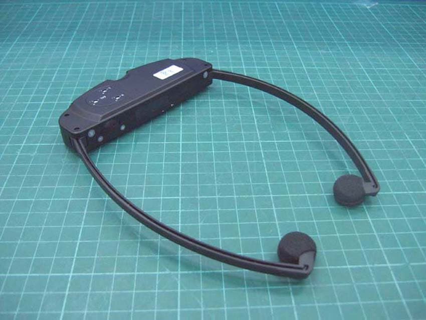
Click to zoom
Application Details
- Equipment Class
- DXT - Part 15 Low Power Transceiver, Rx Verified
- Date of Grant
- Mar 15, 2007
- Application Purpose
- Original Equipment
- Date of Application
- Mar 15, 2007
- Equipment Note
- TV Listener
- Frequency Range
- 2.80000000 - 2.80000000
- Country
- United States
Documents & Files
Document Text
Text extracted from the exhibit documents filed with the FCC. Open a document above to read the original.
Users Manual
Use Artwork For:Product Color:Printed Material: Issued for: Revision: C Implement: Artwork Provided: Printing: Color Scheme: Others: Others: Paper Stock:Color of Stock: Cut: Binding/Folding:Others: Prototype/Sample(s): Prior to production sample(s) approval required by Clarity: Special Instructions: Weight of Stock: Others: Others: Size: 5"x8" Prepared by: John Hawbaker Quantity: Number of samples to be submitted for approval: 3 Colors: Product: C120 Product Manual Vendor: Reason for Revision: added battery warning per regulatory ("risk of explosion..." text) Supplied By: Pms colors are: Date: 01-18-07 APP-USA CTAP FTRI FTRI COMBO color of lens color of button color of LED housing color APP-USA CTAP FTRI FTRI COMBO APP-USA User Guide Quick Guide Product Graphics Product Label Battery Warning Label Warning Label Product Inlay Function Inlay Template Product Sticker Battery Sticker Box Sticker Addendum Gift Box Product Directory Others: CTAP FTRI FTRI COMBO APP-USA U.K. FTRI FTRI COMBO ITALY JAPAN CTAP APP-USA RADIO SHACK CANADA BELL SOUTH EnglishFrenchSpanishPortugueseJapaneseItalian RevisionCreation ImmediatelyAs Running Change Laser Output Film PosFilm NegsLinoCDZipEmailPDFjpg LithoSilk ScreenDigital Press Xerox 1/0 Color (color on one side only) 1/1 color (color on two sides) 2/0 colors (two colors on one side only) BlackWhite 4 Color Process (CMYK) Spot Color (PMS) Gloss VarnishDull Varnish Glossc2s (coated 2 sides) c1s (coated 1 side) Matte CoverPaperCardCardboardCorrugated Board Transparent Self Adhesive Sticker Paper Self Adhesive Sticker Mylar Self Adhesive Sticker Mylar Inlay Die-Cut Radius Corners Trim FoldParallel Fold Accordion Fold Saddle Stitch (Stapled) Perfect Bound ProvidedNot Provided YESNO E N G L I S H E S P A ~ N O L C120 TM User Guide Clarity ® Wireless TV Amplifier CONTENTS Parts checklist ...................................................................................4 Quick Reference Guide ..................................................................5 Features ................................................................................................6 Clarity Power Control .................................................................6 Telephone Ring Notification ...........................................................6 Public IR Address Usage ...............................................................6 Setup Guidelines C120 Transmitter ..........................................................................7 C120 Headset ..............................................................................11 Troubleshooting ..............................................................................14 Technical Specifications ..............................................................15 Regulatory Compliance ...............................................................16 IMPORTANT SAFETY INFORMATION Hearing Safety The C120 is intended to reproduce sounds at a high volume. Damage to your hearing is a possibility if used improperly. To prevent any possible damage to your hearing, please observe the following guidelines: 1. Turn the volume all the way down on the headset before putting it on. 2. When adjusting the volume to a comfortable level, start at the minimum volume and slowly turn the volume up. This will ensure the volume is set at the minimum level needed to hear clearly. Medical Device Safety Before using C120 TV Amplifier in the area of a pacemaker or other medical device, please consult a physician or the manufacturer of the medical device. This will help determine if this product can be used in conjunction with other medical devices in the area. 45 C120 Quick Reference Guide PARTS CHECKLIST 5. AC Adapter 4. Microphone 6. Rechargeable Batteries (2) 7. User Guide 2. Transmitter 1. Headset 9. RCA Stereo Cable 10. RCA 3.5 mm Stereo Cable 8. Flathead Screwdriver 1. Headset 2. Transmitter 3. Headset Pouch 4. Microphone 5. AC Adapter 6. Rechargeable Batteries (2) 7. User Guide 8. Flathead Screwdriver 9. RCA Cable (dual red and white plugs) 10. RCA – 3.5mm Cable 11. Phone Line Cord 11. Phone Line Cord 3. Headset Pouch QUICK START GUIDELINES 1. Plug in AC adapter. 2. Place battery in headset and place headset in C120 base to charge battery overnight. 3. Connect RCA (red and white) cables. a. IF the television has two RCA (red and white) ports labeled “OUT,” or a 3.5mm audio jack, set the “STEREO/MONO” switch to “STEREO.” b. IF the television has only one RCA (white) port, set “STEREO/MONO” switch to “MONO.” 4. For telephone ring notification, connect the phone cord from the wall to “LINE” and connect cord from “PHONE” to telephone. 5. To POWER-ON headset, place on head. As the arms are spread apart, the unit powers on. The C120 must be fully charged for 8 hours before first use. STOP 2 2 OFF ON OFF ON 5 LR L (WHITE) R (RED) STEREO RCA JACKS TV BACK VIEW RCA 3.5mm cable (provided) (if TV only has a 3.5mm audio port) STEREO / MONO STEREO / MONO L/MONO TV C120 L R DC12VLINE PHONE STEREOMONO MIC 1 3 3b 3a 4 4 3 67 SETTING UP THE C120 TRANSMITTER Important Setup Guidelines The C120 TV Amplifier transmitter may be placed on top of a television or shelf. Do not place objects in between the transmitter base and the headset receiver, as it will block the signal to the headset. It is important to read the following guidelines to ensure the proper function of your headset. 1. For the clearest signal, place the base at eye level or above. As illustrated in Fig. 1, the clearest signal emitted from the base is in a straight line, directly in front of the base. The base must be clearly visible from where you will be using the headset. 2. Sunlight can cause interference with the product and cause problems such as buzz, static, or hiss. As a result, this product cannot be placed in direct sunlight or be used outdoors. 3. The headset must be located in the same room as the base and no more than 38 feet from the base. Multiple headsets may be used with a si…
Text truncated - open the document above for the full version.
External Photos
Photo 1: External photo of EUT C120 Photo 2: External photo of EUT C120 Photo 3: External photo of EUT C120 Photo 4: External photo of EUT C120 Photo 5: External photo of Series C120 Photo 6: External photo of Series C120 Photo 7: External photo of Microphone C120 Photo 8: External photo of Audio cable C120 Photo 9: External photo of Audio cable C120 Photo 10: External photo of Battery C120 Photo 11: External photo of Battery C120 Photo 12: External photo of Battery C120 Photo 13: External photo of Adapter Photo 14: External photo of Adapter
ID Label/Location Info
4cm 5.5cm FCC ID Label Location
Internal Photos
Photo 1: Internal photo of EUT C120 Photo 2: Internal photo of EUT Photo 3: Internal photo of EUT C120 Photo 4: Internal photo of EUT C120 Photo 5: Internal photo of EUT C120 Photo 6: Internal photo of EUT C120 Photo 7: Internal photo of EUT C120 Photo 8: Internal photo of EUT C120
Test Report
FCC ID. : ACEC120A Report No.: EME-070093 Page 1 of 19 EMC TEST REPORT Report No. : EME-070093 Model No. : C120, C110, C115 Issued Date : Feb. 13, 2007 Applicant : Clarity, a division of Plantronics 4289 Bonny Oaks Drive, Suit 106, Chattanooga TN37406 Test By : Intertek Testing Services Taiwan Ltd. No. 11, Ko-Tze-Nan Chia-Tung Li, Shiang-Shan District, Hsinchu, Taiwan This test report consists of 19 pages in total. It may be duplicated completely for legal use with the allowance of the applicant. It shall not be reproduced except in full, without the written approval of Intertek Laboratory. The test result(s) in this report only applies to the tested sample(s). Kevin Chen Project Engineer Reviewed By Jerry Liu FCC ID. : ACEC120A Report No.: EME-070093 Page 2 of 19 Table of Contents Summary of Tests ............................................................................................................. 3 1. General information...................................................................................................... 4 1.1 Identification of the EUT........................................................................................ 4 1.2 Additional information about the EUT ................................................................... 4 1.3 Peripherals equipment ............................................................................................ 5 2. Test specifications.........................................................................................................6 2.1 Test standard ........................................................................................................... 6 2.2 Operation mode ...................................................................................................... 6 2.3 Test equipment........................................................................................................ 7 3. Conducted emission test FCC 15.207 .......................................................................... 8 3.1 Operating environment ........................................................................................... 8 3.2 Test setup & procedure ........................................................................................... 8 3.3 Emission limit......................................................................................................... 8 3.4 Conducted emission data FCC 15.207 ................................................................... 9 4. Radiated emission test FCC 15.223.............................................................................11 4.1 Operating environment ..........................................................................................11 4.2 Test setup & procedure ..........................................................................................11 4.3 Radiated emission limit ........................................................................................ 13 FCC ID. : ACEC120A Report No.: EME-070093 Page 3 of 19 Summary of Tests TV Listener -Model: C120 FCC ID: ACEC120A Test Reference Results Conducted Emission of AC Power 15.207 Pass Radiated Emission test 15.223, 15.209 Pass FCC ID. : ACEC120A Report No.: EME-070093 Page 4 of 19 1. General information 1.1 Identification of the EUT Manufacturer : Clarity, a division of Plantronics Product : TV Listener Model No. : C120 FCC ID. : ACEC120A Frequency Range : 2.3MHz & 2.8MHz Channel Number : 2 channels Frequency of each channel : 2.3MHz & 2.8MHz Type of Modulation : FM Power Supply : 100-240Vac, 50/60Hz with adapter (Model: DSA-5P-12FUS 120030) Power Cord : N/A Sample Received : Feb. 05, 2007 Test Date(s) : Feb. 09, 2007 ~ Feb. 13, 2007 1.2 Additional information about the EUT The EUT is a TV Listener, and was defined as information technology equipment. Intertek verified the model listed as below is series model to C120 (EUT). The difference please refer to the following table: Model Number Difference C120 Earphone with switch, 2.3MHz, 2.8MHz C110 Earphone without switch, 2.3MHz, 2.8MHz C115 Earphone with switch, 2.3MHz, 2.8MHz For more detail features, please refer to Users manual as file name “Installation guide.pdf” FCC ID. : ACEC120A Report No.: EME-070093 Page 5 of 19 1.3 Peripherals equipment Peripherals Manufacturer Product No. Serial No. FCC ID Telephone TENTEL K-903S 0514000940 FCC DoC Approved Telephone TENTEL K-903S 0514000477 FCC DoC Approved iPOD Apple 5U606C4KUPRN/A FCC DoC Approved Exchange Board Teltone 250-00193-07 94948 FCC DoC Approved FCC ID. : ACEC120A Report No.: EME-070093 Page 6 of 19 2. Test specifications 2.1 Test standard The EUT was performed according to the procedures in FCC Part 15 Subpart C Section 15.223. 2.2 Operation mode The EUT was operated in continuously transmitting mode. FCC ID. : ACEC120A Report No.: EME-070093 Page 7 of 19 2.3 Test equipment Equipment Brand Frequency range Model No. Intertek ID No. Next Cal. Date EMI Test Receiver Rohde & Schwarz9kHz~2.75GHz ESCS 30 EC303 04/27/2007 Spectrum Analyzer Rohde & Schwarz9kHz~30GHz FSP 30 EC353 08/06/2007 Spectrum Analyzer Rohde & Schwarz20Hz~40GHz FSEK 30 EC365 11/12/2007 Loop Antenna RolfHeine 20Hz~30MHz LA-285 EC357 05/29/2007 Bilog Antenna SCHWARZBECK25MHz~1.7GHz VULB 9160EC368 05/07/2009 Pre-Amplifier MITEQ 100MHz~26.5GHz919981 EC373 02/13/2008 Controller HDGmbH N/A HD 100 EP317-1 N/A Antenna Tower HDGmbH N/A MA 240 EP317-2 N/A Turn Table HDGmbH N/A DS 420S EP317-3 N/A LISN Rohde & Schwarz9KHz~30MHz ESH3-Z5 EC344 01/15/2008 Note: The above equipments are within the valid calibration period. FCC ID. : ACEC120A Report No.: EME-070093 Page 8 of 19 3. Conducted emission test FCC 15.207 3.1 Operating environment Temperature: 23 Relative Humidity: 54 % Atmospheric Pressure: 1023 hPa 3.2 Test setup & procedure (1) RJ11 10m x 1 (2) Audio cable 1.5m x 1 (3) Microphone Line 2m x1 (4) RJ11 10m x1 The EUT are connected to the main power through a line impedance stabilization network (LISN). This pro…
Text truncated - open the document above for the full version.
Test Setup Photos
Photo 1: Radiated Emission Test set-up photo C120 Photo 2: Radiated Emission Test set-up photo C120
Test Setup Photos
Photo 1: Conducted Emission Test Set-up photo C120 Photo 2: Conducted Emission Test Set-up photo C120
Contact Information
Applicant
JAMIE VAN DEN BERGH(CEO)
Technical Contact
Intertek Testing Services Taiwan Ltd.Jerry Liu
[email protected]886 3 519 1411
11 ln, Ko Tze Nan, Chia-Tung Li · Taiwan
Non-Technical Contact
Intertek Testing Services Taiwan Ltd.
[email protected]886 3 519 1411
Test Firm
Intertek Testing Services Taiwan Ltd.Alpha Liu
Technical Specifications
| # | Rule Parts | Frequency Range | Power Output |
|---|---|---|---|
| 2 | 15C | 2.8 MHz - 2.8 MHz | - |
Other Applications from Clarity, A Division of Plantronics, Inc.

ACEPAL101V1
Jun 03, 2013Mobile phone
Equipment Class
DSS - Part 15 Spread Spectrum Transmitter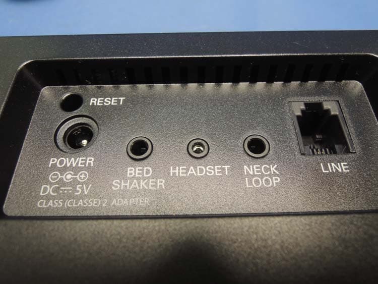
ACEENSEMBLE
Nov 29, 2012Corded Telephone with TAM and WiFi Feature
Equipment Class
DTS - Digital Transmission System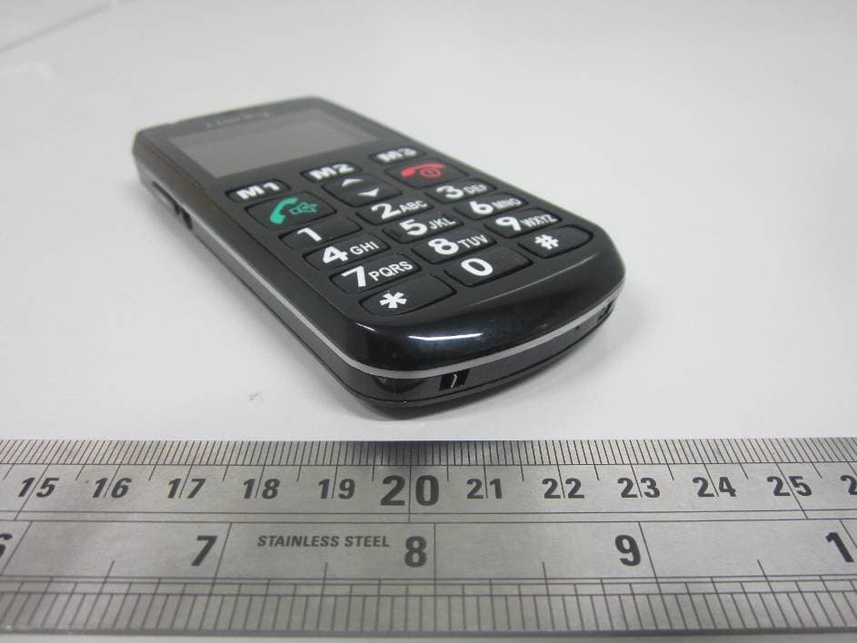
ACEPAL101
Jan 24, 2012GSM Senior Mobile Phone
Equipment Class
DSS - Part 15 Spread Spectrum Transmitter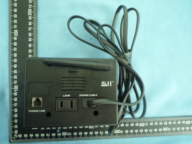
ACEAL11RTXS
Jun 28, 2010Alert Master Home Alert System
Equipment Class
DSR - Part 15 Remote Control/Security Device Transceiver
ACED100TXS
Jun 28, 2010Doorbell
Equipment Class
DSC - Part 15 Security/Remote Control Transmitter