ACEC42305.8GHZ CORDLESS PHONE
Clarity, A Division of Plantronics, Inc.
Click to zoom
Application Details
- Equipment Class
- DSS - Part 15 Spread Spectrum Transmitter
- Date of Grant
- Mar 10, 2008
- Application Purpose
- Original Equipment
- Date of Application
- Mar 06, 2008
- Equipment Note
- 5.8GHZ CORDLESS PHONE
- Frequency Range
- 5725.80900000 - 5848.88900000
- Country
- United States
Documents & Files
Document Text
Text extracted from the exhibit documents filed with the FCC. Open a document above to read the original.
Users Manual
User Guide 5.8 GHz Amplified Cordless Speakerphone With Caller ID & Call Waiting (Supports up to 3 additional handsets) E S P A Ñ O L F R A N Ç A I S E N G L I S H POWER IN USE CHARGE PAGE RINGER STYLE VOLUME B O O S T MENU TALK CL/FL C4220 ABC 1 2 GHI 4 JKL 5 MNO 6 PQRS WXYZ TUV 7 8 0 9 DEF 3 * # RD/P C4220 TM TABLE OF CONTENTS Getting Started Safety Instruction ..........................................................................4 Parts Checklist ..............................................................................7 Quick Reference Guide ...............................................................8 Installation ........................................................................................12 Telephone Operation Basic Handset Operation ..........................................................13 Basic Base Operation .....................................................................17 Other Features on Handset ......................................................18 Date and Time .............................................................................19 Initial Setup ......................................................................................21 Phonebook ...................................................................................23 Caller ID .......................................................................................27 Troubleshooting ..............................................................................30 Technical Specifications .............................................................32 FCC Requirements and Regulations .......................................33 Warranty and Service ..................................................................36 Introduction Thank you for purchasing the C4220 5.8 GHz amplified cordless phone, from Clarity. Using our patented Digital Clarity Power, the C4220 clearly amplifies incoming sound up to 50 dB while cutting out background noise. This User Guide and Quick Start Guide will provide you with the information you need to use your C4220 effectively, easily and safely. Read this manual thoroughly before using this telephone. Keep the manual near the phone for easy reference. 4 SAVE THESE INSTRUCTIONS IMPORTANT SAFETY INSTRUCTIONS When using your telephone equipment, basic safety precautions should always be followed to reduce the risk of fire, electric shock and injury to persons including the following: 1. Read and understand all instructions. 2. Follow all warnings and instruc- tions marked on the telephone. 3. Do not use this telephone near a bath tub, wash basin, kitchen sink or laundry tub, in a wet basement, near a swimming pool or anywhere else there is water. 4. Avoid using a telephone (other than a cordless type) during a storm. There may be a remote risk of electrical shock from lightning. 5. Do not use the telephone to report a gas leak in the vicinity of the leak. 6. Unplug this telephone from the wall outlets before cleaning. Do not use liquid cleaners or aerosol cleaners on the telephone. Use a damp cloth for cleaning. 7. Place this telephone on a stable surface. Serious damage and/or injury may result if the telephone falls. 8. Do not cover the slots and open- ings on this telephone. This telephone should never be placed near or over a radiator or heat register. This tele- phone should not be placed in a built-in installation unless proper ventilation is provided. 9. Operate this telephone using the electrical voltage as stated on the base unit or in the owner’s manual. If you are not sure of the voltage in your home, consult your dealer or local power company. 10. Do not place anything on the power cord. Install the telephone where no one will step or trip on the cord. 11. Do not overload wall outlets or extension cords as this can increase the risk of fire or electrical shock. 12. Never push any objects through the slots in the telephone. They can touch dangerous voltage points or short out parts that could result in a risk of fire or electrical shock. Never spill liquid of any kind on the telephone. 13. To reduce the risk of electrical shock, do not take this phone apart. Opening or removing covers may expose you to dangerous voltages or other risks. Incorrect reassembly can cause electric shock when the appliance is subsequently used. 14. Unplug this product from the wall outlet and refer servicing to the manufacturer under the following conditions: A. When the power supply cord or plug is frayed or damaged. B. If liquid has been spilled into the product. C. If the telephone has been exposed to rain or water. D. If the telephone does not operate normally by following the operating instructions. Adjust only those controls that are covered by the operating 5 IMPORTANT SAFETY INSTRUCTIONS SAVE THESE INSTRUCTIONS instructions. Improper adjust- ment may require extensive work by a qualified technician to restore the telephone to normal operation. E. If the telephone has been dropped or the case has been damaged. F. If the telephone exhibits a distinct change in performance. 15. Never install telephone wiring during a lightning storm. 16. Never install telephone jacks in wet locations unless the jack is specifi- cally designed for wet locations. 17. Never touch uninsulated telephone wires or terminals unless the tele- phone line has been disconnected at the network interface. 18. Use caution when installing or modifying telephone lines. 19. Use only the power cord and batteries indicated in the manual. Do not dispose of batteries in a fire. They may explode. Check with local codes for possible special disposal instructions. 20. Plug the AC adaptor into the outlet that is nearest and most accessible to the telephone. Exposure to high volume sound levels may damage your hearing. Although there is no single volume setting that is appropriate for everyone, you should always use the handset with the volume set at moderate levels and avoid pro - longed exposure to high…
Text truncated - open the document above for the full version.
Users Manual
User Guide 5.8 GHz Amplified Cordless Speakerphone /Answering Machine With Caller ID & Call Waiting (Supports up to 3 additional handsets) BOOST TALK MENU CL/FL RD/P ABC GHI PQRS WXYZ JKL TUV DEF MNO ON OFF DEL REC OGM PLAY OGM FLASH REDIAL BOOST MUTE POWER IN USE CHARGE PLAY STOP REW F FWD RINGER ON/OFF 1 1 2 4 7 8 9 0 5 6 3 4 5 6 9 8 0 7 2 3 * * # # ABC DEF GHI PQRS WXYZ JKL TUV MNO C4230 E S P A ñ O L F R A N ç A I S E N G L I S H C4230 TM TABLE OF CONTENTS Getting Started Safety Instruction ..........................................................................4 Parts Checklist...............................................................................7 Quick Reference Guide ...............................................................8 Installation.........................................................................................13 Telephone Operation ....................................................................14 Basic Handset Operation ..........................................................14 Basic Base Operation .....................................................................18 Other Features on Handset ......................................................21 Date and Time .............................................................................23 Initial Setup.......................................................................................24 Phonebook ...................................................................................26 Caller ID .......................................................................................30 Telephone Answering Machine .................................................33 Access from handset ..................................................................35 Access from a Remote Location ..............................................40 Troubleshooting ..............................................................................42 Technical Specifications .............................................................44 FCC Requirements and Regulations .......................................45 Warranty and Service ..................................................................48 Introduction Thank you for purchasing the C4230, 5.8 GHz amplified cordless phone, from Clarity. Using our patented Digital Clarity Power, the C4230 clearly amplifies incoming sound up to 50 dB while cutting out background noise. This phone has many features including a digital answering machine and speakerphone. This User Guide and Quick Start Guide will provide you with the information you need to use your C4230 effectively, easily and safely. Read this manual thoroughly before using this telephone. Keep the manual near the phone for easy reference. 4 SAVE THESE INSTRUCTIONS SAFETY INSTRUCTIONS When using your telephone equipment, basic safety precautions should always be followed to reduce the risk of fire, electric shock and injury to persons including the following: 1. Read and understand all instructions. 2. Follow all warnings and instruc- tions marked on the telephone. 3. Do not use this telephone near a bath tub, wash basin, kitchen sink or laundry tub, in a wet basement, near a swimming pool or anywhere else there is water. 4. Avoid using a telephone (other than a cordless type) during a storm. There may be a remote risk of electrical shock from lightning. 5. Do not use the telephone to report a gas leak in the vicinity of the leak. 6. Unplug this telephone from the wall outlets before cleaning. Do not use liquid cleaners or aerosol cleaners on the telephone. Use a damp cloth for cleaning. 7. Place this telephone on a stable surface. Serious damage and/or injury may result if the telephone falls. 8. Do not cover the slots and open- ings on this telephone. This telephone should never be placed near or over a radiator or heat register. This tele- phone should not be placed in a built-in installation unless proper ventilation is provided. 9. Operate this telephone using the electrical voltage as stated on the base unit or in the owner’s manual. If you are not sure of the voltage in your home, consult your dealer or local power company. 10. Do not place anything on the power cord. Install the telephone where no one will step or trip on the cord. 11. Do not overload wall outlets or extension cords as this can increase the risk of fire or electrical shock. 12. Never push any objects through the slots in the telephone. They can touch dangerous voltage points or short out parts that could result in a risk of fire or electrical shock. Never spill liquid of any kind on the telephone. 13. To reduce the risk of electrical shock, do not take this phone apart. Opening or removing covers may expose you to dangerous voltages or other risks. Incorrect reassembly can cause electric shock when the appliance is subsequently used. 14. Unplug this product from the wall outlet and refer servicing to the manufacturer under the following conditions: A. When the power supply cord or plug is frayed or damaged. B. If liquid has been spilled into the product. C. If the telephone has been exposed to rain or water. D. If the telephone does not operate normally by following the operating instructions. Adjust only those controls that are covered by the operating instructions. Improper adjust- ment may require extensive 5 SAFETY INSTRUCTIONS SAVE THESE INSTRUCTIONS work by a qualified technician to restore the telephone to normal operation. E. If the telephone has been dropped or the case has been damaged. F. If the telephone exhibits a distinct change in performance. 15. Never install telephone wiring during a lightning storm. 16. Never install telephone jacks in wet locations unless the jack is specifi- cally designed for wet locations. 17. Never touch uninsulated telephone wires or terminals unless the tele- phone line has been disconnected at the network interface. 18. Use caution when installing or modifying telephone lines. 19. Use only the …
Text truncated - open the document above for the full version.
Cover Letter(s)
Appendix B1 Letter of Agency for FCC Certification August 14, 2007 To whom it may concern, Letter of Agency I, an officer of Clarity, A Division of Plantronics, Inc do hereby authorize Intertek Testing Services (Mr. Ken Sit/ Mr. Tommy Leung) to act on our behalf in front of the Federal Communications Commission with respect to all matters relating to certification of equipment under Part 15 and/or Part 95 of the FCC Rules until further notice. I further certify that no party (as defined in §1.2002(b) of CFR 47, 2004) to this application, including myself, is subject to a denial of federal benefits, that includes FCC benefits, pursuant to Section 5301 of the Anti-Drug Abuse Act of 1988, 21 U.S.C., 862. Regards, Christy Swafford Quality Analyst Phone 423-629-3512 Fax 423-622-0414 [email protected]
Cover Letter(s)
August 14, 2007 To whom it may concern, Request for Permanent Confidentiality Under FCC Part 15 Certification FCC ID: ACEC4230 Request is hereby submitted by Clarity, A Division of Plantronics, Inc to withhold permanently from public review certain portions of the application for equipment certification for the referenced FCC identifiers. This request for confidentiality is made pursuant to 47 CFR § 0.457(d) and 0.459 of the FCC Rules. In particular, the following sections of the application are to be kept permanently confidential and Clarity, A Division of Plantronics, Inc reserves the right to discern which parties can obtain access to these information: • Schematics [FILENAME: ACEC4230_circuit_C4220.pdf, ACEC4230_circuit_C4230.pdf] • Detailed Block diagrams [FILENAME: ACEC4230_block_C4220.pdf, ACEC4230_block_C4230.pdf] • Detailed Operational/Functional Description [FILENAME: ACEC4230_descri_C4220.pdf,ACEC4230_descri_C4230.pdf] The rationale for request for confidentiality is as followings: This information represents intellectual property of Clarity, A Division of Plantronics, Inc and it is subject to competition. We have invested considerable time and materials in research and development to produce the referenced product. Disclosure of the permanently confidential portions of this application to competitors would not only give them significant competitive advantages in developing similar products, but would also disclose successful implementation of unpublished, leading edge technology developed by us. If you have questions or need further information, please contact the undersigned. Regards, Christy Swafford Quality Analyst Phone 423-629-3512 Fax 423-622-0414 [email protected]
Cover Letter(s)
Revision: 02 Page 32 of 39 10. C4230 Basic Operation (Base and Handset) 10.1 Registration Before the handset can make a call, it has to register to a base unit. This can be done either manually or automatically. For C4230, the following identification codes are generated during power up. A. Handset IPEI (International Portable Equipment Identity) code: Bits (0 -> 5) - 000000; Bits (6 -> 15) - EMC (Equipment Manufacturer’s Code) code (DSPG 0x010); Bits (16 -> 35) - PESN (Portable Equipment Serial Number) (524K combinations) B. Base RFPI (Radio Fixed Part Identity) code: Bits (0 -> 7) - Frequency information; Bits (8 -> 9) - 00; Bits (10 -> 19) - EMC code (DSPG 0x010); Bits (20 -> 36) – FPN (Fixed Part Number) (65K combinations); Bits (37 -> 39) - 000. These codes are registered to each other during registration process. In addition, a 128 bit authentication code (made up of four 32 bits short authentication code) is generated randomly through the registration process. These codes are checked when the handset/base communicate with each other. Registration (Manual Method): Press the handset “MENU” button or the “MENU” softkey. Press “UP” / “DOWN” button to scroll to “Initial Setup”. Press “SELECT” softkey. LCD will show the selection arrow pointing at “REGISTRATION”. Press and hold the base “PAGE” switch for ~2 seconds until the “INUSE” LED on the base blinks. Press the “SELECT” softkey on the handset. The base and handset will start the registration process. Registration (Automatic Method): Connect AC power to the base unit first.
External Photos
INTERTEK TESTING SERVICES External Photos - Model: C4220 FCC ID: ACEC4230 external photos - 1 of 2 INTERTEK TESTING SERVICES External Photos - Model: C4220 FCC ID: ACEC4230 external photos - 2 of 2
External Photos
INTERTEK TESTING SERVICES External Photos - Model: C4230 FCC ID: ACEC4230 external photos - 1 of 2 INTERTEK TESTING SERVICES External Photos - Model: C4230 FCC ID: ACEC4230 external photos - 2 of 2
ID Label/Location Info
C4220 Rev.1 09/07/2007 32mm x 12mm 8.3mm 9V DC 500 mA USE ONLY WITH CLASS (CLASSE) 2 POWER SOURCE 70255 70255 IC:1186C-C4230 C4220 Rev.1 09/07/2007 25mm x 6mm IC:1186C-C4230 19mm x 7.5mm Braille Label C4220 Rev.1 09/07/2007
ID Label/Location Info
C4230 Rev.1 09/07/2007 10.7mm 55mm x 40mm 70255 USE ONLY WITH CLASS (CLASSE) 2 POWER SOURCE 9V DC 500 mA 70255 C4230 Rev.0 08/18/2007 AA SIZE 1.5V AA SIZE 1.5V AA SIZE 1.5V AA SIZE 1.5V C4230 Rev.0 08/18/2007 C4230 Rev.0 08/18/2007 IC:1186C-C4230 25mm x 6mm IC:1186C-C4230 19mm x 7.5mm C4230 Rev.0 08/18/2007 Braille Label C4230 Rev.1 09/07/2007
Internal Photos
INTERTEK TESTING SERVICES Internal photos - Model: C4230 FCC ID: ACEC4230 internal photos - 1 of 14 Base Unit assembly Base Unit Main PCB comp side INTERTEK TESTING SERVICES Internal photos - Model: C4230 FCC ID: ACEC4230 internal photos - 2 of 14 Base Unit Main PCB solder side (View 1) Base Unit Main PCB solder side (View 2) INTERTEK TESTING SERVICES Internal photos - Model: C4230 FCC ID: ACEC4230 internal photos - 3 of 14 Base Unit DAM Display front side Base Unit DAM Display rear side INTERTEK TESTING SERVICES Internal photos - Model: C4230 FCC ID: ACEC4230 internal photos - 4 of 14 Base Unit, Lamp Flasher Port front side Base Unit, Lamp Flasher Port rear side INTERTEK TESTING SERVICES Internal photos - Model: C4230 FCC ID: ACEC4230 internal photos - 5 of 14 Base Unit Keypad front side Base Unit Keypad rear side INTERTEK TESTING SERVICES Internal photos - Model: C4230 FCC ID: ACEC4230 internal photos - 6 of 14 Base Unit Page Key front side Base Unit Page Key rear side INTERTEK TESTING SERVICES Internal photos - Model: C4230 FCC ID: ACEC4230 internal photos - 7 of 14 Base Unit Function LED front side Base Unit Function LED rear side INTERTEK TESTING SERVICES Internal photos - Model: C4230 FCC ID: ACEC4230 internal photos - 8 of 14 Base Unit Oscillator PCB comp side (View 1) Base Unit Oscillator PCB comp side (View 2) INTERTEK TESTING SERVICES Internal photos - Model: C4230 FCC ID: ACEC4230 internal photos - 9 of 14 Base Unit Oscillator PCB comp side (View 3) INTERTEK TESTING SERVICES Internal photos - Model: C4230 FCC ID: ACEC4230 internal photos - 10 of 14 Handset assembly Handset Main PCB comp side INTERTEK TESTING SERVICES Internal photos - Model: C4230 FCC ID: ACEC4230 internal photos - 11 of 14 Handset Main PCB display side (View 1) Handset Main PCB display side (View 2) INTERTEK TESTING SERVICES Internal photos - Model: C4230 FCC ID: ACEC4230 internal photos - 12 of 14 Handset Function LED front side Handset Function LED rear side INTERTEK TESTING SERVICES Internal photos - Model: C4230 FCC ID: ACEC4230 internal photos - 13 of 14 Handset Oscillator PCB comp side (View 1) Handset Oscillator PCB comp side (View 2) INTERTEK TESTING SERVICES Internal photos - Model: C4230 FCC ID: ACEC4230 internal photos - 14 of 14 Handset Oscillator PCB comp side (View 3)
RF Exposure Info
INTERTEK TESTING SERVICES FCC ID:ACEC4230 RF exposure - 2 of 2 For Maximum Permissible Exposure (MPE) evaluation of the base unit, the maximum power density at 20 cm from this mobile transmitter shall be less than the General Population / Uncontrolled MPE limit in OET Bulletin 65. For the base unit of tested model of C4220, the maximum field strength measured (FS) was 118.9 dBμV/m. The distance (D) between the antenna and the equipment under test (EUT) was 3 meters. And the maximum source-based time-averaging duty factor in four-handsets operation is 39.2%. From these data, the exposed power density at a distance (R) of 20cm from the center of radiation of the antenna can be calculated according to OET Bulletin 65 as follow: The radiated power = (FS*D) 2 / 30 = 232.87 mW The radiated (EIRP) source-based time-averaging output power = (232.87 * 0.392) mW = 91.29 mW The power density at 20 cm from the antenna = EIRP / 4πR 2 = 0.0182 mW cm -2 In the frequency range of 1,500 - 100,000MHz, the MPE limit is 1.0 mWcm -2 for general population and uncontrolled exposure. As the measured power density at 20cm from the transmitter is lower than the MPE limit, the compliance to the MPE limit can be ensured by indicating the minimum 20cm separation between the transmitter's radiating structures and body of the user or nearby persons. The following RF exposure statement is proposed to be included in the user manual: “ FCC RF Radiation Exposure Statement Caution: To maintain compliance with the FCC’s RF exposure guidelines, place the base unit at least 20cm from nearby persons.”
RF Exposure Info
INTERTEK TESTING SERVICES FCC ID:ACEC4230 RF exposure - 1 of 2 For Maximum Permissible Exposure (MPE) evaluation of the base unit, the maximum power density at 20 cm from this mobile transmitter shall be less than the General Population / Uncontrolled MPE limit in OET Bulletin 65. For the base unit of tested model of C4230, the maximum field strength measured (FS) was 112.6 dBμV/m. The distance (D) between the antenna and the equipment under test (EUT) was 3 meters. And the maximum source-based time-averaging duty factor in four-handsets operation is 39.2%. From these data, the exposed power density at a distance (R) of 20cm from the center of radiation of the antenna can be calculated according to OET Bulletin 65 as follow: The radiated power = (FS*D) 2 / 30 = 54.59 mW The radiated (EIRP) source-based time-averaging output power = (54.59 * 0.392) mW = 21.40 mW The power density at 20 cm from the antenna = EIRP / 4πR 2 = 0.0043 mW cm -2 In the frequency range of 1,500 - 100,000MHz, the MPE limit is 1.0 mWcm -2 for general population and uncontrolled exposure. As the measured power density at 20cm from the transmitter is lower than the MPE limit, the compliance to the MPE limit can be ensured by indicating the minimum 20cm separation between the transmitter's radiating structures and body of the user or nearby persons. The following RF exposure statement is proposed to be included in the user manual: “ FCC RF Radiation Exposure Statement Caution: To maintain compliance with the FCC’s RF exposure guidelines, place the base unit at least 20cm from nearby persons.”
RF Exposure Info
©2005 A Test Lab Techno Corp. Page 1 of 62 This report shall not be reproduced except in full, without the written approval of A Test Lab Techno Corp. Rev.02 This document may be altered or revised by A Test Lab Techno. Corp. personnel only, and shall be noted in the revision section of the document A Test Lab Techno Corp. Changan Lab:No. 140 -1, Changan Street, Bade City, Taoyuan County, Taiwan R.O.C. Te l:886-3-271-0188 / Fax:886-3-271-0190 SAR EVALUATION REPORT Test Report No. : 0708FS17 Applicant : Clarity, a Division of Plantronics, Inc. FCC ID : ACEC4230 Trade Name : Clarity Model Name : C4230 Battery Type : Ni-MH Battery (3.6V,780mAh) EUT Type : 5.8GHz Frequency Hopping Spread Spectrum Cordless Phone with Caller ID Dates of Test : Jan. 02 ~ Jan. 03, 2008 Test Environment : Ambient Temperature: 22 ±3 ° C Relative Humidity:40 - 70 % Test Specification : Standard C95.1-1999 IEEE Std. 1528-2003 Max. SAR : 0.992 W/kg Head SAR 1.520 W/kg Body SAR FCC Rule Part(s) : 2.1093;FCC/OET Bulletin 65 Supplement C [July 2001] SAR Measurement Requirements For 3-6GHz:FCC Test Lab : Changan Lab 1. The test operations have to be performed with cautious behavior, the test results are as attached. 2. The test results are under chamber environment of A Test Lab Techno Corp. A Test Lab Techno Corp. does not assume responsibility for any conclusions and generalizations drawn from the test results with regard to other specimens or samples. 3. The measurement report has to be written approval of A Test Lab Techno Corp. It may only be reproduced or published in full. Country Huang 20080128 Sam Chuang 20080128 Test Report No:0708FS17 Page 2 of 62 ©2005 A Test Lab Techno Corp. Rev.02 Contents 1. Description of Equipment Under Test (EUT)............................................................................................... 3 2. Other Accessories ......................................................................................................................................... 5 3. Introduction .................................................................................................................................................... 8 4. SAR Definition ................................................................................................................................................ 9 5. SAR Measurement Setup ............................................................................................................................ 10 6. System Components ................................................................................................................................... 12 6.1 DASY4 E-Field Probe System ............................................................................................................ 12 6.2 Data Acquisition Electronic (DAE) System.......................................................................................... 14 6.3 Robot................................................................................................................................................... 15 6.4 Measurement Server .......................................................................................................................... 15 6.5 Device Holder for Transmitters ........................................................................................................... 15 6.6 Phantom - SAM v4.0 ........................................................................................................................... 16 6.7 Data Storage and Evaluation .............................................................................................................. 16 7. Test Equipment List..................................................................................................................................... 19 8. Tissue Simulating Liquids .......................................................................................................................... 20 8.1 Liquid Confirmation ............................................................................................................................. 21 9. Measurement Process................................................................................................................................. 23 9.1 Device and Test Conditions ................................................................................................................ 23 9.2 System Performance Check ............................................................................................................... 24 9.3 Dosimetric Assessment Setup ............................................................................................................ 25 9.4 Spatial Peak SAR Evaluation.............................................................................................................. 27 10. Measurement Uncertainty ........................................................................................................................... 28 11. SAR Test Results Summary........................................................................................................................ 30 11.1 Head SAR ........................................................................................................................................... 30 11.2 Body SAR_ 15mm space .................................................................................................................... 31 11.3 Body SAR_ Belt clip ............................................................................................................................ 31 11.4 Setup photo......................................................................................................................................... 32 11.5 Std. C95.1-1999 RF Exposure Limit ................................................................................................... 35 12. Conclusion ..............................................…
Text truncated - open the document above for the full version.
Test Report
INTERTEK TESTING SERVICES Maximum 20dB RF Bandwidth Plots FCC ID: ACEC4230 20dB - 1 of 2 Plot B2A(C4220) Plot B2B (C4220) A0 INTERTEK TESTING SERVICES Maximum 20dB RF Bandwidth Plots FCC ID: ACEC4230 20dB - 2 of 2 Plot B2C(C4220) A0
Test Report
INTERTEK TESTING SERVICES Maximum 20dB RF Bandwidth Plots FCC ID: ACEC4230 20dB - 1 of 2 Plot B2A(C4230) Plot B2B (C4230) A0 INTERTEK TESTING SERVICES Maximum 20dB RF Bandwidth Plots FCC ID: ACEC4230 20dB - 2 of 2 Plot B2C(C4230) A0 INTERTEK TESTING SERVICES Maximum 20dB RF Bandwidth Plots FCC ID: ACEC4230 20dB - 1 of 2 Plot H2A(C4230) Plot H2B (C4230) A0 INTERTEK TESTING SERVICES Maximum 20dB RF Bandwidth Plots FCC ID: ACEC4230 20dB - 2 of 2 Plot H2C(C4230) A0
Test Report
INTERTEK TESTING SERVICES Average Channel Occupancy Time Plots FCC ID: ACEC4230 avetime - 1 of 3 Plot B5A(C4230) Plot B5B (C4230) INTERTEK TESTING SERVICES Average Channel Occupancy Time Plots FCC ID: ACEC4230 avetime - 2 of 3 Plot B5C(C4230) Plot H5A(C4230) INTERTEK TESTING SERVICES Average Channel Occupancy Time Plots FCC ID: ACEC4230 avetime - 3 of 3 Plot H5B (Single-slot operation) (C4230) Plot H5C (Single-slot operation) (C4230)
Test Report
INTERTEK TESTING SERVICES Minimum Number Hopping Frequencies Plots FCC ID: ACEC4230 chno - 1 of 7 Plot B3A(C4230) Plot B3B(C4230) INTERTEK TESTING SERVICES Minimum Number Hopping Frequencies Plots FCC ID: ACEC4230 chno - 2 of 7 Plot B3C(C4230) Plot B3D (C4230) INTERTEK TESTING SERVICES Minimum Number Hopping Frequencies Plots…
Text truncated - open the document above for the full version.
Contact Information
Applicant
JAMIE VAN DEN BERGH(CEO)
Test Firm
Intertek Testing Services Hong KongBilly Chow
Technical Specifications
| # | Rule Parts | Frequency Range | Power Output |
|---|---|---|---|
| 2 | 15C | 5.73 GHz - 5.85 GHz | 196.00 mW |
Other Applications from Clarity, A Division of Plantronics, Inc.

ACEPAL101V1
Jun 03, 2013Mobile phone
Equipment Class
DSS - Part 15 Spread Spectrum Transmitter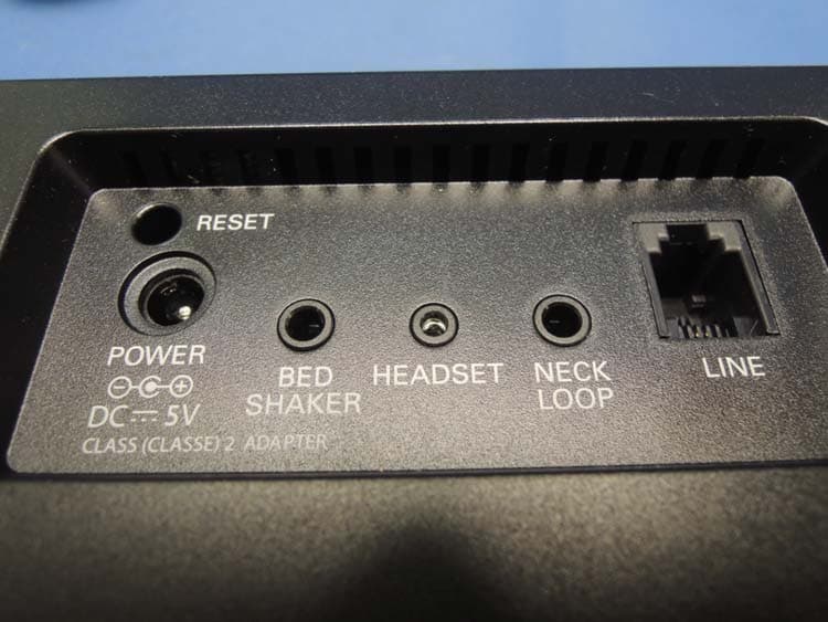
ACEENSEMBLE
Nov 29, 2012Corded Telephone with TAM and WiFi Feature
Equipment Class
DTS - Digital Transmission System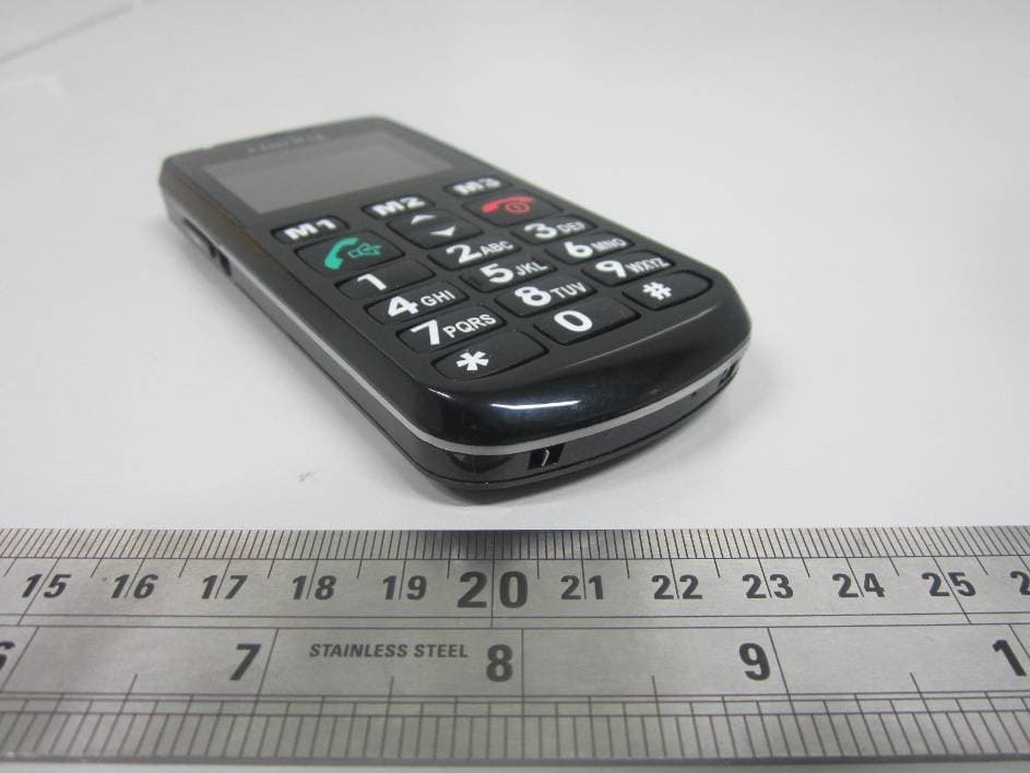
ACEPAL101
Jan 24, 2012GSM Senior Mobile Phone
Equipment Class
DSS - Part 15 Spread Spectrum Transmitter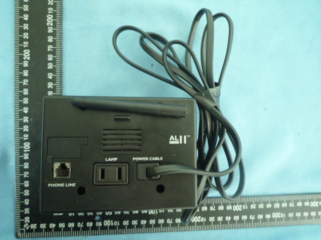
ACEAL11RTXS
Jun 28, 2010Alert Master Home Alert System
Equipment Class
DSR - Part 15 Remote Control/Security Device Transceiver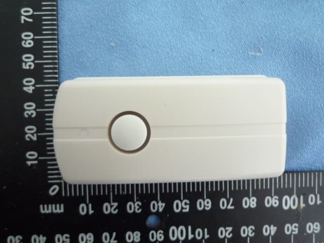
ACED100TXS
Jun 28, 2010Doorbell
Equipment Class
DSC - Part 15 Security/Remote Control Transmitter