ACECLS45I2.4GHz 40 Channel Analog Modulation Cordless Phone
Clarity, A Division of Plantronics, Inc.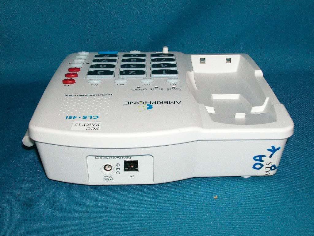
Click to zoom
Application Details
- Equipment Class
- DXT - Part 15 Low Power Transceiver, Rx Verified
- Date of Grant
- Nov 07, 2003
- Application Purpose
- Original Equipment
- Date of Application
- Nov 07, 2003
- Equipment Note
- 2.4GHz 40 Channel Analog Modulation Cordless Phone
- Frequency Range
- 2474.00000000 - 2475.95000000
- Country
- United States
Documents & Files
Document Text
Text extracted from the exhibit documents filed with the FCC. Open a document above to read the original.
Users Manual
© 2003 Plantronics, Inc. 76513.000 B 9/03 ∆ CLS • 45i Dual Speaker Amplified Cordless Phone with Call-Waiting Caller ID Ameriphone products are manufactured by Walker, a Division of Plantronics, Inc. 12082 Western Avenue Garden Grove, CA 92841 VOICE (800) 874-3005 or (714) 897-0808 TTY (800) 772-2889 or (714) 897-1111 FAX (714) 897-4703 email: [email protected] www.ameriphone.com Operating Instructions English• Francais • Español ii When using your telephone equipment, basic safety precautions should always be followed to reduce the risk of fire, electric shock and injury to persons including the following: 1. Read and understand all instructions. 2. Follow all warnings and instructions marked on the telephone. 3. Do not use this telephone near a bathtub, wash basin, kitchen sink or laundry tub, in a wet basement, near a swimming pool or anywhere else where there is water. 4. Avoid using a telephone (other than a cordless type) during a storm.There may be a remote risk of electrical shock from lightning. 5. Do not use the telephone to report a gas leak in the vicinity of the leak. 6. Unplug this telephone from the wall outlets before cleaning. Do not use liquid cleaners or aerosol cleaners on the telephone. Use a damp cloth for cleaning. 7.Place this telephone on a stable surface. Serious damage and/or injury may result if the telephone falls. 8. Do not cover the slots and openings on this telephone. It should never be placed near or over a radiator or heat register.This telephone should not be placed in a built-in installation unless proper ventilation is provided. 9. Operate this telephone using the electrical voltage as stated on the base unit or the owner’s manual. If you are not sure of the voltage in your home, consult your dealer or local power company. 10. Do not place anything on the power cord. Install the telephone where no one will step or trip on the cord. 11. Do not overload wall outlets or extension cords as this can increase the risk of fire or electrical shock. 12. Never push any objects through the slots in the telephone.They can touch dangerous voltage points or short out parts that could result in a risk of fire or electrical shock. Never spill liquid of any kind on the telephone. 13. To reduce the risk of electrical shock, do not take this phone apart. Opening or removing covers may expose you to dangerous voltages or other risks. Incorrect reassembly can cause electric shock when the appliance is subsequently used. 14. Unplug this product from the wall outlets and refer servicing to the manufacturer under the following conditions: A. When the power supply cord or plug is frayed or damaged. B. If liquid has been spilled into the product. C.If the telephone has been exposed to rain or water. D.If the telephone does not operate normally by following the operating Important Safety Instructions iii instructions. Adjust only those controls that are covered by the operating instructions. Improper adjustment may require extensive work by a qualified technician to restore the telephone to normal operation. E. If the telephone has been dropped or the case has been damaged. F.If the telephone exhibits a distinct change in performance. 15. Never install telephone wiring during a lightning storm. 16. Never install telephone jacks in wet locations unless the jack is specifically designed for wet locations. 17. Never touch un-insulated telephone wires or terminals unless the telephone line has been disconnected at the network interface. 18. Use caution when installing or modifying telephone lines. 19. Use only the power cord and batteries indicated in this manual. Do not dispose of batteries in a fire.They may explode. Check with local codes for possible special disposal instructions. Save These Instructions ADDITIONAL SAFETY NOTES FOR CANADIAN USERS The following items are included as part of the CS-03 Requirements.The standard connecting arrangement for the equipment is CA11A.This product meets the applicable Industry Canada technical specifications. NOTICE:The Canadian Department of Communications label identifies certified equipment.This certification means that the equipment meets certain telecommu- nications network protective operational and safety requirements.The Department does not guarantee that the equipment will operate to the user’s satisfaction. Before installing this equipment, users should ensure that it is permissible to be connected to the facilities of the local telecommunications company.The equipment must also be installed using an acceptable method of connection. In some cases, the company’s inside wiring associ- ated with a single line individual service may be extended by means of a certified connector assembly (telephone extension cord). The customer should be aware that com- pliance with the above conditions may not prevent degradation of service in some situations. Repairs to certified equipment iv Safety Instructions (continued) should be made by an authorized Canadian maintenance facility designated by the supplier. Any repairs or alterations made by the user to this equipment, or equipment malfunctions, may give the telecommunications company cause to requestthe user disconnect the equipment. Users should ensure for their own protection that the electrical ground connections of the power utility, telephone lines and internal metallic water pipe system, if present, are connected together.This precaution may be particu- larly important in rural areas. CAUTION: Users should not attempt to make such connections themselves, but should contact the appropriate electric inspection authority, or electrician, as appropriate. The Ringer Equivalent Number is an indication of the maximum number of terminals allowed to be connected to a telephone interface.The termination on an interface may consist of any combina- tion of devices subject only to the requirement that the sum of the Ringer Equivalent Number of all the devices not exceed five. Save These …
Text truncated - open the document above for the full version.
Users Manual
disconnect the equipment until the problem is resolved. This telephone equipment is not intended to be repaired and it contains no repairable parts. Opening the equipment or any attempt to perform repairs will void the warranty. For service or repairs, call 1-800-874-3005. Connection to party line service is subject to state tariffs. Contact the state public utility commission, public service commis- sion or corporation commission for information. If your home has specially wired alarm equipment connected to the telephone line, ensure the installation of this tele- phone equipment does not disable your alarm equipment. If you have questions about what will disable alarm equipment, consult your telephone company or a qualified installer. This telephone equipment is hearing aid compatible. We recommend the installation of an AC surge arrester in the AC outlet to which this equipment is connected.The telephone companies report that electrical surges, typically lighting transients, are very destructive to customer terminal equip- ment connected to AC power sources Customer-Owned Coin/Credit Card Phones To comply with state tariffs, the telephone company must be given notification prior to connection. In some states, the state public utility commission, public service commission or corporation commission must give prior approval of connection. Part 15 of FCC Rules Information This device complies with part 15 of the FCC Rules. Operation is subject to the following two conditions: 1. This device may not cause harmful interference, and 2. this device must accept any interfer- ence received, including interference that may cause undesired operation. Your telephone equipment has been tested and found to comply with the limits of a Class B digital device, pursuant to Part 15 of FCC rules.These limits are designed to provide reasonable protection against harmful interference in residential installation. This equipment generates, uses, and can radiate radio frequency energy and, if not installed and used in accordance with the instructions, may cause harmful interfer- ence to radio communications. However, there is no guarantee that interference 27 will not occur in a particular installation; if this equipment does cause harmful inter- ference to radio or television reception, which can be determined by turning the equipment off and on, you are encouraged to try to correct the interference by one of the following measures: 1. Where it can be done safely, reorient the receiving television or radio antenna. 2. To the extent possible, relocate the television, radio or other receiver with respect to the telephone equip- ment. (This increases the separation between the telephone equipment and the receiver) 3. Connect the telephone equipment into an outlet on a circuit difference from that to which the television, radio, or other receiver is connected. 4. Consult the dealer or an experienced radio/TV technician for help. CAUTION: Changes or modifications not expressly approved by the manufac- turer responsible for compliance could void the user’s authority to operate the equipment. THE PARTY RESPONSIBLE FOR PROD- UCT COMPLIANCE: Ameriphone Products by Walker®, A Division of Plantronics, Inc. 12082 Western Avenue Garden Grove, CA 92841 Telephone: 800-874-3005 Industry Canada Technical Specifications This product meets the applicable Industry Canada technical specifications. Before installing this equipment, users should ensure that it is permissible to be connected to the facilities of the local telecommunications company.The equip- ment must also be installed using an acceptable method of connection. In some cases, the company's inside wiring associ- ated with a single line individual service may be extended by means of a certified connector assembly (telephone extension cord).The customer should be aware that compliance with the above conditions may not prevent degradation of service in some situations. Repairs to certified equipment should be made by an authorized Canadian mainte- nance facility designated by the supplier. Any repairs or alterations made by the user to this equipment, or equipment malfunctions, may give the telecommunica- tions company cause to request the user to disconnect the equipment. Users should ensure for their own pro- tection that the electrical ground connec- tions of the power utility, telephone lines and internal metallic water pipe system, if present, are connected together.This 28 Regulatory Compliance Important Information for Customers (continued)
Block Diagram
Revision: 01 Page 13 of 33 RF Module (Base) Block Diagram Revision: 01 Page 14 of 33 RF Module (Handset) Block Diagram
External Photos
External photos FCC ID: ACECLS45I External photos FCC ID: ACECLS45I
ID Label/Location Info
FCC ID:ACECLS45I MADE IN CHINA Ameriphone® Model: CLS45i IC: 1186C-CLS45I CLS45i Rev.2 10/06/2003 CLS45i Rev.2 10/06/2003 AA SIZE 1.5V AA SIZE 1.5V AA SIZE 1.5V AA SIZE 1.5V CLS-45i DUAL SPEAKER CORDLESS AMPLIFIED TELEPHONE Complies with 47CFR Part 68 Technical Requirements Reg. No.: US: ACEW909BCLS45I FCC ID: ACECLS45I IC: 1186C-CLS45I IC REN: 0.4 REN: 0.9B USOC Jack: RJ11C This device complies with Part 15 of the FCC rules. Operation is subject to the following two conditions: (1) This device may not cause harmful interference, and (2) This device must accept any interference received, including interference that may cause undesired operation. Privacy of communications may not be ensured when using this phone. Four batteries: Base: use only AA alkaline batteries; Handset: use only 3.6V 750mAhAA NiMH battery pack AC/DC Adapter: Ameriphone #950 9VDC500mA 12082 Western Ave., Garden Grove, CA 92841 Voice: (800) 874-3005 - TTY: (800) 772-2889 Ameriphone products are manufactured by Walker, a Division of Plantronics Inc., Precision engineered in the USA; made in China; Patent Pending MFG. CODE: HAC L46802 9/03 I.T.E. 70255 A 2/3 GP75AAH3BMJZ GPI International Ltd.
Internal Photos
Internal photos FCC ID: ACECLS45I Base assembly (View 1) Base assembly (View 2) Internal photos FCC ID: ACECLS45I Base assembly (View 3) Base Main PCB comp side (View 1) Internal photos FCC ID: ACECLS45I Base Main PCB comp side (View 2) Base Main PCB comp side (View 3) Internal photos FCC ID: ACECLS45I Base Main PCB solder side Base keypad front side Internal photos FCC ID: ACECLS45I Base keypad rear side (View 1) Base keypad rear side (View 2) Internal photos FCC ID: ACECLS45I Base Oscillator PCB comp side Base Oscillator PCB solder side Internal photos FCC ID: ACECLS45I Handset assembly Handset Main PCB comp side (View 1) Internal photos FCC ID: ACECLS45I Handset Main PCB comp side (View 2) Handset Main PCB display side Internal photos FCC ID: ACECLS45I Handset Oscillator PCB comp side Handset Oscillator PCB solder side
Operational Description
Revision: 01 Page 1 of 33 CLS-45i CIRCUIT DESCRIPTION CONTENT 1. Introduction 2. Functional Blocks of CLS-45i Handset 3. CLS-45i Handset Unit Circuit Block Description 4. Functional Blocks of CLS-45i Base unit 5. CLS-45i Base Unit Circuit Block Description 6. Functional Blocks of the RF Module 7. RF Module Circuit Block Description 8. CLS-45i Basic Operation (Base) 9. CLS-45I Basic Operation (Handset) 10. CLS-45I Basic Operation (Base and Handset) 11. Test Mode Operation Revision: 01 Page 2 of 33 1. Introduction The model CLS-45i is a 40 channel (2.4GHz) cordless telephone. This unit is made up of two parts: a. A Handset unit. b. A Base unit. 2. Functional Blocks of CLS-45i Handset The block diagram of CLS-45i handset unit is as shown below. It is made up of the following parts: 2.1 Keyboard Matrix, Switches and Function LED 2.2 MCU and MCU Interface 2.3 RF Module 2.4 Compander 2.5 Data Shaper 2.6 Charge and Control 2.7 Low Battery Detector 2.8 Buzzer 2.9 Audio Circuit Revision: 01 Page 3 of 33 CLS-45i Handset Block Diagram Revision: 01 Page 4 of 33 3. CLS-45i Handset Unit Circuit Block Description 3.1 Keyboard Matrix, Switches and Function LED The keyboard consists of the following keys: • CALL ID – for Caller ID operation • DELETE ( BACK) – for menu operation • FLASH (EXIT) –– provides timed On/Off hook function • TALK – for On/Off hook control • UP/DOWN – for menu operation • REDIAL (FWD ) – redials the last number or provides a pause during dialing. • 1, 2, 3, 4, 5, 6, 7, 8, 9, *, 0, # – numeric keys • CHANNEL (SETUP) – for changing RF carrier frequency • SPEAKER – for On/Off hook control in speakerphone mode • INTERCOM (ENTER) – for base and handset communication • AMPLIFY – provides amplifier On/Off hook function • MEM – for memory program and dialing The keyboard is connected to Pins 84 to 94, 97 of the MCU (MCU1). The switches consist of the followings: • RINGER ON/OFF – turns On/Off the ringer buzzer This is connected to pins 97 and 88 of MCU. The jacks consist of the followings: • HEADSET – for connection of an external microphone and receiver • AUDIO – for connection of an external speaker • REMOTE – for connection of an external switch. This is connected to pins 97 and 90 of MCU. The function LEDs consist of the followings: • NEWCALL/INUSE (NCALL1 – RED) – Located under the lens on the top right hand corner. On/Off when handset is Off-hook/On-hook. Blinks when there is New Call to be reviewed. • AMPLIFIER (AMP1 – RED) – Located under the “AMPLIFY” key. On/Off when the receiver amplifier extra gain is On/Off. • SPEAKERPHONE (SPK1 – RED) – On/Off when the speakerphone is On/Off. Located under the “SPEAKERPHONE” key. • BACKLIGHT (LED1 – LED14, LED15 - Amber) – Located under the Revision: 01 Page 5 of 33 keyboard and LCD backlight. On for a short time when any key is pressed • RINGER (RING1 - Red) – Located under the red lens on the back of the unit. Flashes when the telephone line rings These LEDs are controlled by pins 91, 98, 96, 66 and 99 of MCU. The display format of the LCD is as shown below. The display is controlled by pins 13 – 70 of MCU. 3.2 MCU and MCU Interface The controller of the handset is MCU1. The frequency of the crystal used is 32.768 KHz. It controls the functions of the handset through the keyboard interface and signals from the base unit. The data to and from the base goes through pin 69 (data from base) and pin 71 (data to base). 3.3 RF Module For operation and frequency see RF module section. It receives the PLL data through pins 5, 6, 7 from MCU pins 93, 94 and 95. The antenna located at the top of the unit and is permanent attached to RF module through a copper wire. 3.4 Compander A compander U3 is used for improving the S/N of transmit and receive audio signals. 3.5 Data Shaper The information which sent from base unit is recovered by the amplifier Q306 and Q305. Revision: 01 Page 6 of 33 3.6 Charge and Control ZD1, D304, D305, D306, D307, Q1 provide polarity and over-voltage protection during battery charging. The charge signal is detected by pin 84 of the MCU. When the handset is put into the base cradle, a negative pulse is sent to pin 74 of the MCU. 3.7 Low Battery Detector The battery voltage is detected by U4 and Q14. The signal is sent to pin 67 of MCU. 3.8 Buzzer Q3 is the buzzer signal amplifier and driven by the MCU pins 72. 3.9 Audio Circuit When operating in receiver mode, speech signal is picked up by the internal microphone MIC1 and sent to the telephone line through amplifier U1B, the compander U3 and the RF module. The incoming speech is received through the RF module, the compander, the amplifier U1A, and amplifier U6. When AMPLIFIER is On,, extra gain is inserted in this audio path by speakerphone IC U11, and tone control U1C and U1D. When operating in speakerphone mode, speech signal is picked up by MIC1 and sent to the telephone line through U11, the compander U3 and the RF module. The incoming speech is received through the RF module, the compander, the amplifier U11, and amplifier U5. The tone control and amplifier functions are disabled when in speakerphone mode. The headset jack is for external receiver and microphone. The audio jack is for external speaker when in receiver mode. Revision: 01 Page 7 of 33 4. Functional Blocks of CLS-45i Base Unit The block diagram of CLS-45i base unit is as shown below. It is made up of the following parts: l Power Supply l MCU and MCU Interface l RF Module l Compander l Data Shaper l Charge and Control l Telephone Line Interface l Ring Signal Detector l Base Ringer l Keyboard Matrix, Switches and Function LED Revision: 01 Page 8 of 33 CLS-45i Base Unit Block Diagram Revision: 01 Page 9 of 33 5. CLS-45i Base Unit Circuit Block Description 5.1 Power Supply The base unit is powered by an AC adapter (9V dc). The voltage regulator (BU5) regulates the input DC to 5V. This provides power to every part of the unit. When there is no AC power, BQ10 and BQ11 are turned on to connect the backup batteries …
Text truncated - open the document above for the full version.
Test Report
• The test results reported in this report shall refer only to the sample actually tested and shall not refer or be deemed to refer to bulk from which such a sample may be said to have been obtained. • This report shall not be reproduced except in full without prior authorization form Intertek Testing Services Limited FCC ID: ACECLS45I Intertek Testing Services Hong Kong Ltd. 2/F., Garment Centre, 576 Castle Peak Road, Kowloon, Hong Kong. Tel: (852) 2173 8888 Fax: (852) 2741 1693 Website: www.hk.intertek-etlsemko.com Walker Equipment Corporation Application For Certification 2.4GHz 40 Channel Analog Modulation Cordless Phone with Caller ID and Dual Speakerphone (FCC ID: ACECLS45I) 03153661 TL/ Ann Choy October 14, 2003 INTERTEK TESTING SERVICES FCC ID: ACECLS45I i LIST OF EXHIBITS INTRODUCTION EXHIBIT 1: General Description EXHIBIT 2: System Test Configuration EXHIBIT 3: Emission Results EXHIBIT 4: Equipment Photographs EXHIBIT 5: Product Labelling EXHIBIT 6: Technical Specifications EXHIBIT 7: Instruction Manual EXHIBIT 8: Security Code Information INTERTEK TESTING SERVICES FCC ID: ACECLS45I ii MEASUREMENT/TECHNICAL REPORT Walker Equipment Corporation - MODEL: CLS-45i FCC ID: ACECLS45I This report concerns (check one:) Original Grant X Class II Change Equipment Type : Cordless Telephone (example : computer, modem, transmitter, etc.) Deferred grant requested per 47 CFR 0.457(d)(1)(ii)? Yes No X If yes, defer until : date Company Name agrees to notify the Commission by: date of the intended date of announcement of the product so that the grant can be issued on that date. Transition Rules Request per 15.37 ? Yes No X If no, assumed Part 15, Subpart C for intentional radiator - the new 47 CFR [08-20-02 Edition] Provision. Report prepared by: Tommy Leung Intertek Testing Services. 2/F., Garment Centre, 576 Castle Peak Road, Kowloon, Hong Kong. Phone : 852-2173-8538 Fax: 852-2741-1693 INTERTEK TESTING SERVICES FCC ID: ACECLS45I iii Table of Contents 1.0 General Description.....................................................................................................2 1.1 Product Description..................................................................................................2 1.2 Related Submittal(s) Grants....................................................................................3 1.3 Test Methodology.....................................................................................................3 1.4 Test Facility...............................................................................................................3 2.0 System Test Configuration........................................................................................5 2.1 Justification................................................................................................................5 2.2 EUT Exercising Software........................................................................................5 2.3 Support Equipment List and Description...............................................................6 2.4 Measurement Uncertainty.......................................................................................7 2.5 Equipment Modification...........................................................................................7 3.0 Emission Results.........................................................................................................9 3.1 Field Strength Calculation.....................................................................................10 3.2 Radiated Emission Configuration Photograph - Base Unit..............................11 3.3 Radiated Emission Data - Base Unit...................................................................12 3.4 Radiated Emission Configuration Photograph - Handset.................................15 3.5 Radiated Emission Data - Handset......................................................................16 3.6 Radiated Emission on the bandedge...................................................................19 3.7 Line Conducted Configuration Photograph - Base Unit....................................21 3.8 Line Conducted Emission Data - Base Unit........................................................22 4.0 Equipment Photographs..........................................................................................25 5.0 Product Labelling.......................................................................................................27 6.0 Technical Specifications..........................................................................................29 7.0 Instruction Manual.....................................................................................................31 8.0 Security Code Information.......................................................................................33 INTERTEK TESTING SERVICES FCC ID: ACECLS45I iv List of attached file Exhibit type File Description filename Test Report Test Report report.pdf Operation Description Technical Description descri.pdf Test Setup Photo Radiated Emission for Base config photos.doc Test Setup Photo Radiated Emission for Handset config photos.doc Test Report Emission Plot emission.pdf Test Setup Photo Conducted Emission config photos.doc Test Report Conducted Emission Test Result conduct.pdf External Photo External Photo external photos.doc Internal Photo Internal Photo internal photos.doc Block Diagram Block Diagram block.pdf Schematics Circuit Diagram circuit.pdf ID Label/Location Label Artwork and Location label.pdf User Manual User Manual manual.pdf User Manual FCC Information fcc information.pdf INTERTEK TESTING SERVICES FCC ID: ACECLS45I 1 EXHIBIT 1 GENERAL DESCRIPTION INTERTEK TESTING SERVICES FCC ID: ACECLS45I 2 1.0 General Description 1.1 Product Description The CLS-45i is a 2.4GHz 40 Channel Analog Modulation Cordless Phone with Caller ID and Dual Speakerphone. The unit is capable of either tone or pulse dialing. The internal pow…
Text truncated - open the document above for the full version.
Test Report
Report No.:03153661 Talk Mode Ctrl No.:N/A PAGE 1 Tested By:Hong, Report No.:03153661 Scan Settings (1 Range) |--------- Frequencies -----------||----------- Receiver Settings ------------| Start Stop Step IF BW Detector M-Time Atten Preamp OpRge 150k 30M 5k 10k PK+AV 10ms AUTO LN OFF 60dB Final Measurement: x QP / + AV Meas Time: 1 s Subranges: 16 Acc Margin: 20dB Transducer No. Start Stop Name 21 9k 30M EW0698 0 10 20 30 40 50 60 70 80 90 dBuV 100 0.15 MHz 30110 F15Q F15A Report No.:03153661 Talk Mode Ctrl No.:N/A Tested By:Hong, Report No.:03153661 Scan Settings (1 Range) |--------- Frequencies -----------||----------- Receiver Settings ------------| Start Stop Step IF BW Detector M-Time Atten Preamp OpRge 150k 30M 5k 10k PK+AV 10ms AUTO LN OFF 60dB Final Measurement Results: Frequency QP Level QP Limit MHz dBuV dBuV no Results Frequency AV Level AV Limit MHz dBuV dBuV 23.00000 29.0 50.0 * limit exceeded
Test Setup Photos
The Worst Case Configuration Photographs FCC ID: ACECLS45I Radiated Emission – Base Front View Rear View The Worst Case Configuration Photographs FCC ID: ACECLS45I Radiated Emission – Handset Front View Rear View The Worst Case Configuration Photographs FCC ID: ACECLS45I Conducted Emission Front View Rear View The Worst Case Configuration Photographs FCC ID: ACECLS45I Conducted Emission Side View
Test Setup Photos
The Worst Case Configuration Photographs FCC ID: ACECLS45I Radiated Emission – Base Front View Rear View The Worst Case Configuration Photographs FCC ID: ACECLS45I Radiated Emission – Handset Front View Rear View The Worst Case Configuration Photographs FCC ID: ACECLS45I Conducted Emission Front View Rear View The Worst Case Configuration Photographs FCC ID: ACECLS45I Conducted Emission Side View
Contact Information
Applicant
JAMIE VAN DEN BERGH(CEO)
Technical Contact
Intertek Testing Services Hong Kong Ltd.Tommy Leung
[email protected]852-2173-8538
2/F., Garment Centre, · Kowloon, · Hong Kong
Non-Technical Contact
Intertek Testing Services Hong Kong Ltd.Tommy Leung
[email protected]852-2173-8538
Test Firm
Intertek Testing Services Hong KongBilly Chow
Technical Specifications
| # | Rule Parts | Frequency Range | Power Output |
|---|---|---|---|
| 2 | 15C | 2.47 GHz - 2.48 GHz | - |
Other Applications from Clarity, A Division of Plantronics, Inc.

ACEPAL101V1
Jun 03, 2013Mobile phone
Equipment Class
DSS - Part 15 Spread Spectrum Transmitter
ACEENSEMBLE
Nov 29, 2012Corded Telephone with TAM and WiFi Feature
Equipment Class
DTS - Digital Transmission System
ACEPAL101
Jan 24, 2012GSM Senior Mobile Phone
Equipment Class
DSS - Part 15 Spread Spectrum Transmitter
ACEAL11RTXS
Jun 28, 2010Alert Master Home Alert System
Equipment Class
DSR - Part 15 Remote Control/Security Device Transceiver
ACED100TXS
Jun 28, 2010Doorbell
Equipment Class
DSC - Part 15 Security/Remote Control Transmitter