ACELAMPFLASHERLamp Flasher Transmitter
Clarity, A Division of Plantronics, Inc.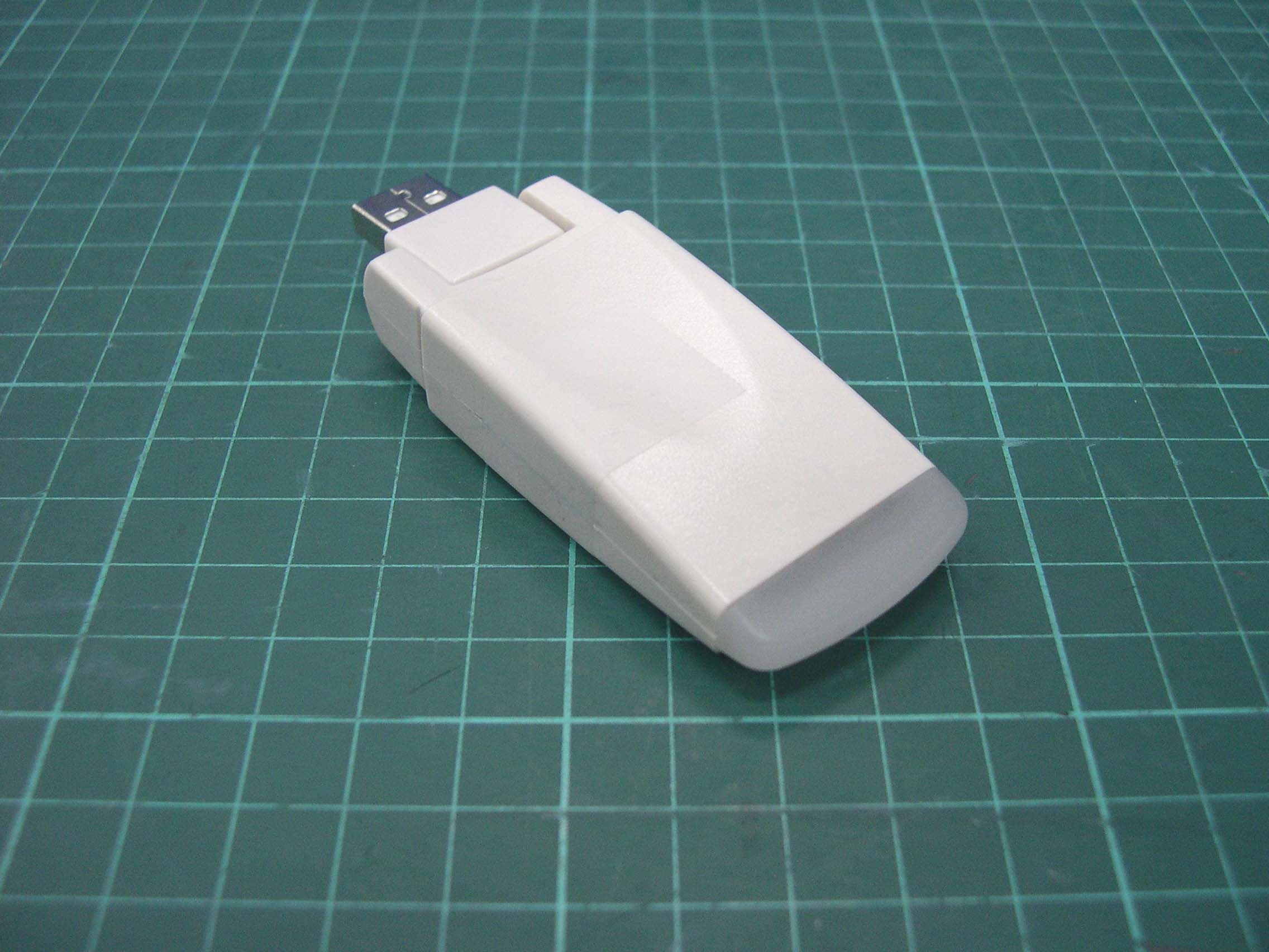
Click to zoom
Application Details
- Equipment Class
- DXX - Part 15 Low Power Communication Device Transmitter
- Date of Grant
- Sep 13, 2005
- Application Purpose
- Original Equipment
- Date of Application
- Sep 13, 2005
- Equipment Note
- Lamp Flasher Transmitter
- Frequency Range
- 315.00000000 - 315.00000000
- Country
- United States
Documents & Files
Document Text
Text extracted from the exhibit documents filed with the FCC. Open a document above to read the original.
Users Manual
Clarity Professional C2210 Notification Accessories User Guide The Bed Shaker and Lamp Flasher provide additional notification for the telephone ringer and alarm clock alert. The following instructions will assist you in connecting these accessories to the C2210. BED SHAKER The Bed Shaker vibrates to alert you of an incoming call or an alarm clock alert. Installation 1. Insert the Bed Shaker plug into the Bed Shaker jack on the top-end of the telephone. (Fig. 1) 2. Place the Bed Shaker under your mattress or pillow. Fig. 1 LAMP FLASHER The Lamp Flasher alerts you of an incoming call by flashing a nearby lamp. Installation 1. Remove the Lamp Transmitter cover. (Fig. 2) 2. Insert the Lamp Transmitter into the Lamp Transmitter jack on the right side of the telephone. (Fig. 3) 3. Insert the Lamp Flasher Power Switch into a nearby electrical outlet. (Fig. 4) NOTE: The Lamp Flasher system has an operating range of 30 feet. 4. Insert the electrical plug of a nearby lamp into the Lamp Flasher Power Switch. 5. Make sure the ON light on the Lamp Flasher Power Switch is lit up. (Fig. 5) NOTE: The On/Off switch on the connected lamp must be on for the system to work. 6. Press the ON/OFF button on the Lamp Flasher Power Switch or press and hold the blue Lamp button on the telephone to turn the connected lamp On and Off. Fig. 2 Fig. 3 Fig. 4 Fig. 5 Federal Communications Commissions Requirements Warning: Changes or modifications to this unit not expressly approved by the party responsible for compliance could void the user’s authority to operate the equipment. This device complies with Part 15 of the FCC Rules. Operation is subject to the following two conditions: (1) this device may not cause harmful interference, and (2) this device must accept any interference received, including interference that may cause undesired operation. The user’s manual or instruction manual for an intentional or unintentional radiator shall caution the user that changes or modifications not expressly approved by the party responsible for compliance could void the user’s authority to operate the equipment. NOTE: This equipment has been tested and found to comply with the limits for a Class B digital device, pursuant to Part 15 of the FCC Rules. These limits are designed to provide reasonable protection against harmful interference in a residential installation. This equipment generates, uses and can radiate radio frequency energy and, if not installed and used in accordance with the instructions, may cause harmful interference to radio communications. However, there is no guarantee that interference will not occur in a particular installation. If this equipment does cause harmful interference to radio or television reception, which can be determined by turning the equipment off and on, the user is encouraged to try to correct the interference by one or more of the following measures: • Reorient or relocate the receiving antenna. • Increase the separation between the equipment and receiver. • Connect the equipment into an outlet on a circuit different from that to which the receiver is needed. • Consult the dealer or an experienced radio/TV technician for help. Warranty and Service Power Specifications Clarity Service Center Frequency: 315 Mhz 4289 Bonny Oaks Drive Voltage: 115 Vac/60Hz Chattanooga, Tennessee 37406 Current: 8A/Max USA Tel: (800) 426-3738 Fax: (800) 325-8871 ©2005 Clarity, a Division of Plantronics, Inc. All Rights Reserved. Clarity, Clarity Professional, the amplification device, Clarity and The amplification device combined, Amplifying Your Life, and Clarity Power are trademarks of Plantronics, Inc. Guide Professionnel D'Utilisateur D'Accessoires De l'Avis C2210 De Clarté Le clignoteur de dispositif trembleur et de lampe de lit fournissent l'avis additionnel pour l'alerte de sonnerie de téléphone et de réveille-matin. Les instructions suivantes vous aideront en reliant ces accessoires au C2210. DISPOSITIF TREMBLEUR DE LIT The Bed Shaker vibrates to alert you of an incoming call or an alarm clock alert. Installation 1. Insérez la prise de dispositif trembleur de lit dans le cric de dispositif trembleur de lit sur l'dessus- extrémité du téléphone. (Fig. 1) 2. Placez le dispositif trembleur de lit sous votre matelas ou oreiller. Fig. 1 CLIGNOTEUR DE LAMPE Le clignoteur de lampe vous alerte d'un appel d'arrivée par clignotant une lampe voisine. Installation 1. Enlevez la couverture d'émetteur de lampe. (Fig. 2) 2. Insérez l'émetteur de lampe dans le cric d'émetteur de lampe du bon côté du téléphone. (Fig. 3) 3. Insérez le commutateur de puissance de clignoteur de lampe dans une sortie électrique voisine. (Fig. 4) NOTE: Le système de clignoteur de lampe a une plage de fonctionnement de 30 pieds. 4. Insérez la prise électrique de lampe voisine dans le commutateur de puissance de clignoteur de lampe. 5. Assurez-vous que DESSUS le léger sur le commutateur de puissance de clignoteur de lampe est allumé. (Fig. 5) NOTE: DessusOutre de passage sur la lampe reliée doit être dessus pour que le système travaille. 6. MaintenezOUTRE du bouton sur le commutateur ou la pression de puissance de clignoteur de lampe et tenez le bouton bleu de lampe au telephone pour tourner la lampe reliée marche- arrêt. Fig. 2 Fig. 3 Fig. 4 Fig. 5 Exigences De La Commission Fédérale Des Communications (FCC) Avertissement : Les changements ou les modifications à cette unité pas expressément approuvée par la partie responsable de la conformité ont pu vider l'autorité de l'utilisateur pour actionner l'équipement. Ce dispositif est conforme à la partie 15 des règles de FCC. L'opération est sujette aux deux conditions suivantes : (1) ce dispositif peut ne pas causer l'interférence nocive, et (2) ce dispositif doit accepter n'importe quelle interference reçue, y compris l'interférence qui peut causer l'opération peu désirée. Le manuel d'utilisateur ou le manuel d'instruction pour un radiateur intentionnel ou involontaire avertira l'utilisateur qui c…
Text truncated - open the document above for the full version.
External Photos
Report No.: EME-050119 Photo 1: External photo of EUT Tx Lamp Flasher Report No.: EME-050119 Photo 2: External photo of EUT Tx Lamp Flasher Report No.: EME-050119 Photo 3: External photo of EUT Tx Lamp Flasher Report No.: EME-050119 Photo 4: External photo of EUT Tx Lamp Flasher
ID Label/Location Info
Report No.: EME-050119 ID Location FCC ID: ACELAMPFLASHER; IC: 1186C-LFlasher
Internal Photos
Report No.: EME-050119 Photo 1: Internal photo of EUT Tx Lamp Flasher Report No.: EME-050119 Photo 2: Internal photo of EUT Tx Lamp Flasher Report No.: EME-050119 Photo 3: Internal photo of EUT Tx Lamp Flasher
Test Report
FCC ID. : ACELAMPFLASHER Report No.: EME-050119 Page 1 of 21 EMC TEST REPORT Report No. : EME-050119 Model No. : Lamp Flasher Issued Date : May 17, 2005 Applicant : Clarity, a Division of Plantronics, Inc. 4289 Bonny Oaks Drive 106, Chattanooga, Tennessee 37406, U.S.A. Test By : Intertek Testing Services Taiwan Ltd. No. 11, Ko-Tze-Nan Chia-Tung Li, Shiang-Shan District, Hsinchu, Taiwan This test report consists of 21 pages in total. It may be duplicated completely for legal use with the allowance of the applicant. It shall not be reproduced except in full, without the written approval of Intertek Laboratory. The test result(s) in this report only applies to the tested sample(s). Kevin Chen Project Engineer Reviewed By Jerry Liu FCC ID. : ACELAMPFLASHER Report No.: EME-050119 Page 2 of 21 Table of Contents Summary of Tests ............................................................................................................. 3 1. General information...................................................................................................... 4 1.1 Identification of the EUT ....................................................................................... 4 1.2 Additional information about the EUT .................................................................. 4 1.3 Antenna description ............................................................................................... 5 1.4 Peripherals equipment............................................................................................ 5 2. Test specifications.........................................................................................................6 2.1 Test standard .......................................................................................................... 6 2.2 Operation mode...................................................................................................... 6 2.3 Test equipment ....................................................................................................... 7 3. Conducted emission test FCC 15.207 .......................................................................... 8 3.1 Operating environment .......................................................................................... 8 3.2 Test setup & procedure .......................................................................................... 8 3.3 Emission limit ........................................................................................................ 8 3.4 Conducted emission data FCC 15.207................................................................... 9 4. Radiated emission test FCC 15.231 (b) .......................................................................11 4.1 Operating environment .........................................................................................11 4.2 Test setup & procedure .........................................................................................11 4.3 Radiated emission limit ....................................................................................... 12 4.3.1 Fundamental and harmonics emission limits.................................................... 12 4.3.2 General radiated emission limit ........................................................................ 13 4.4 Calculation of Average Factor ............................................................................. 14 4.5 Radiated emission test data FCC 15.231 ............................................................. 18 4.5.1 Measurement results: Fundamental Radiated Emission Data........................... 18 4.5.2 Measurement results: frequencies above 1GHz................................................ 19 4.6 Measured bandwidth FCC 15.231(C) .................................................................. 21 FCC ID. : ACELAMPFLASHER Report No.: EME-050119 Page 3 of 21 Summary of Tests Remote Control Switch -Model: Lamp Flasher FCC ID: ACELAMPFLASHER Test Reference Results Conducted Emission of AC Power 15.207 Complies Radiated Emission test 15.231(b), 15.209 Complies Measured bandwidth 15.231(c) Complies FCC ID. : ACELAMPFLASHER Report No.: EME-050119 Page 4 of 21 1. General information 1.1 Identification of the EUT Applicant : Clarity, a Division of Plantronics, Inc. Product : Remote Control Switch Trade Name: : Clarity Professional Model No. : Lamp Flasher FCC ID. : ACELAMPFLASHER Frequency Range : 315MHz Channel Number : 1 channel Frequency of each channel : 315MHz Type of Modulation : ASK Power Supply : 115Vac, 60Hz with Adapter (Clarity, C2210) Power Cord : N/A Data Cable : RJ-11 Unshielded Cable 3meter × 1 Sample Received : Jan. 20, 2005 Test Date(s) : Jan. 20, 2005 ~ May 12, 2005 1.2 Additional information about the EUT The EUT is Home Automation. It has been designed and tested to offer safe service provided it is installed, operated, maintained and tested in strict accordance with the instructions and warnings contained in instruction manual. For more detail features, please refer to User's manual as file name “Installation guide.pdf” FCC ID. : ACELAMPFLASHER Report No.: EME-050119 Page 5 of 21 1.3 Antenna description The EUT uses a permanently connected antenna. Antenna Gain : 0dBi Antenna Type : PCB Printed Connector Type : N/A 1.4 Peripherals equipment Peripherals Manufacturer Product No. Serial No. FCC ID Telephone CLARiTY C2210 N/A FCC DoC Approved Exchange Board Teltone 250-00193-07 94948 FCC DoC Approved FCC ID. : ACELAMPFLASHER Report No.: EME-050119 Page 6 of 21 2. Test specifications 2.1 Test standard The EUT was performed according to the procedures in FCC Part 15 Subpart C Section 15.231. 2.2 Operation mode During conducted emission test, the EUT was in normal operating mode. While in other test, it worked in the status of continuously transmitting. FCC ID. : ACELAMPFLASHER Report No.: EME-050119 Page 7 of 21 2.3 Test equipment Equipment Brand Frequency range Model No. Intertek ID No. Next Cal. Dat…
Text truncated - open the document above for the full version.
Test Setup Photos
Report No.: EME-050119 Photo 1: Tx Radiated Emission Set-up Photo Lamp Flasher Report No.: EME-050119 Photo 2: Tx Radiated Emission Set-up Photo Lamp Flasher
Test Setup Photos
Report No.: EME-050119 Photo 1: Conducted Emission Set-up Photo Tx Lamp Flasher Report No.: EME-050119 Photo 2: Conducted Emission Set-up Photo Tx Lamp Flasher
Contact Information
Applicant
JAMIE VAN DEN BERGH(CEO)
Technical Contact
Intertek Testing Services Taiwan Ltd.Jery Liu
+886 3 519 1411
11, Lane 275, Ko Nan 1st Street · Hsinchu · Taiwan
Test Firm
Intertek Testing Services Taiwan Ltd.Alpha Liu
Technical Specifications
| # | Rule Parts | Frequency Range | Power Output |
|---|---|---|---|
| 1 | 15C | 315 MHz - 315 MHz | - |
Other Applications from Clarity, A Division of Plantronics, Inc.

ACEPAL101V1
Jun 03, 2013Mobile phone
Equipment Class
DSS - Part 15 Spread Spectrum Transmitter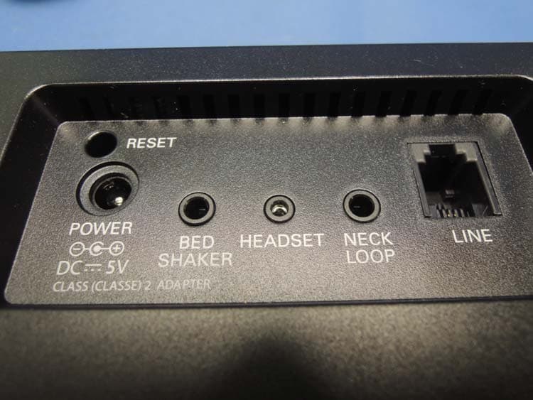
ACEENSEMBLE
Nov 29, 2012Corded Telephone with TAM and WiFi Feature
Equipment Class
DTS - Digital Transmission System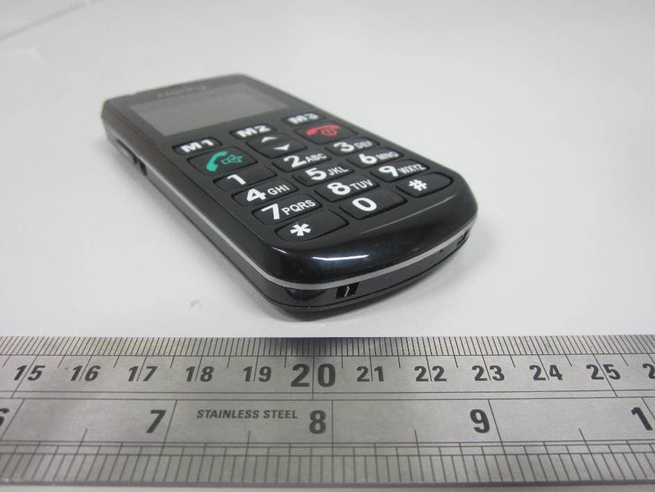
ACEPAL101
Jan 24, 2012GSM Senior Mobile Phone
Equipment Class
DSS - Part 15 Spread Spectrum Transmitter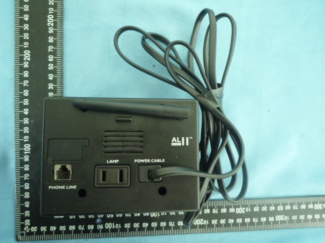
ACEAL11RTXS
Jun 28, 2010Alert Master Home Alert System
Equipment Class
DSR - Part 15 Remote Control/Security Device Transceiver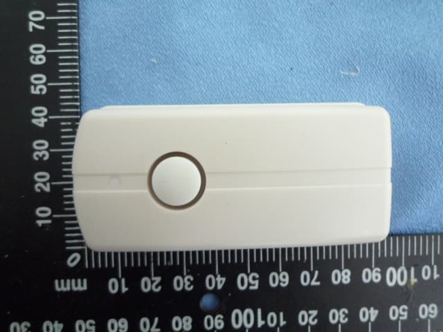
ACED100TXS
Jun 28, 2010Doorbell
Equipment Class
DSC - Part 15 Security/Remote Control Transmitter