ADB9ZW19P1079Wireless LAN module
Furuno USA Inc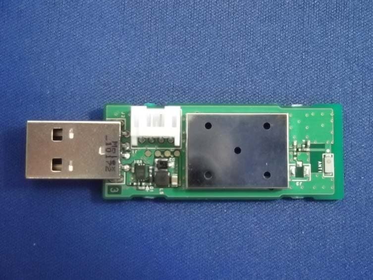
Click to zoom
Application Details
- Equipment Class
- DTS - Digital Transmission System
- Date of Grant
- Dec 23, 2011
- Application Purpose
- Original Equipment
- Date of Application
- Dec 23, 2011
- Equipment Note
- Wireless LAN module
- Frequency Range
- 2412.00000000 - 2462.00000000
- Company
- Furuno USA Inc
- Country
- United States
Documents & Files
Document Text
Text extracted from the exhibit documents filed with the FCC. Open a document above to read the original.
Users Manual
User Manual 802.11bgn WLAN MODULE MODEL WLAN-USB-01 The purpose of this manual is to explain correct way how to integrate module WLAN-USB-01 to the end product. It includes procedures that shall assist you to avoid unforeseen problems. This manual presents information that shows how module and OEM product, where module integrated, complies with regulations in certain regions. Any modifications, not expressly approved by the manufacturer could void the authority to operate in these regions. The 802.11bgn WLAN MODULE, model WLAN-USB-01 is only be professionally installed by OEM or OEM integrator. For detail information concerning type approval of this module (e.g. where this module is already pre-approved) please contact the authorized local distributor or the manufacturer. The system may only be implemented in the configuration that was authorized. Note that any changes or modifications to this equipment not expressly approved by the manufacturer could void the user’s authority to operate this equipment. Regulatory Information Operational Information Wireless Interoperability The end product integrating this module is designed to be interoperable with any wireless LAN product that is based on direct sequence spread spectrum (DSSS) and orthogonal frequency division multiplexing (OFDM) radio technology and to comply with the following standards. ・IEEE Std 802.11b Standard on 2.4GHz Wireless LAN ・IEEE Std 802.11g Standard on 2.4GHz Wireless LAN ・IEEE Std 802.11n Standard on 2.4GHz Wireless LAN Safety The end product integrating this module, like other radio devices, emits radio frequency electromagnetic energy. The level of energy emitted by this device, however, is less than the electromagnetic energy emitted by other wireless devices such as mobile phones. The end product integrating this module operates within the guidelines found in radio frequency safety standards and recommendations. These standards and recommendations reflect the consensus of the scientific community and result from deliberations of panels and committees of scientists who continually review and interpret the extensive research literature. In some situations or environments, the use of the end product integrating this module may be restricted by the proprietor of the building or responsible representatives of the applicable organization. Examples of such situations include the following: ・Using the end product integrating this module onboard airplanes, or ・Using the end product integrating this module in any other environment where the risk of interference with other devices or services is perceived or identified as being harmful. If uncertain of the policy that applies to the use of wireless devices in a specific organization or environment (an airplane, for example), ask for authorization to use the end product integrated into this module before turning it on. USA-Federal Communications Commission (FCC) This equipment has been tested and found to comply with the limits for a Class B digital device, pursuant to Part 15 of FCC Rules. These limits are designed to provide reasonable protection against harmful interference in a residential installation. This equipment generates, uses, and can radiate radio frequency energy. If not installed and used in accordance with the instructions, it may cause harmful interference to radio communications. However, there is no guarantee that interference will not occur in a particular installation. If this equipment does cause harmful interference to radio or television reception, which can be determined by tuning the equipment off and on, the user is encouraged to try and correct the interference by one or more of the following measures: -Reorient or relocate the receiving antenna. -Increase the distance between the equipment and the receiver. -Connect the equipment to outlet on a circuit different from that to which the receiver is connected. -Consult the dealer or an experienced radio/TV technician for help. This device complies with Part 15 of the FCC Rules. Operation is subject to the following two conditions: (1) This device may not cause harmful interference, and (2) This device must accept any interference received, including interference that may cause undesired operation. Any changes or modifications not expressly approved by the party responsible for compliance could void the user’s authority to operate the equipment. Labeling WLAN MODULE “WLAN-USB-01” labeled as below. FCC ID: ADB9ZW19P1079 The label with FCC ID is to be placed on the module. If FCC ID is not visible when the module is installed into the system, “Contains FCC ID: ADB9ZW19P1079” shall be placed on the outside of final host system. Caution: Exposure to Radio Frequency Radiation. This equipment complies with FCC radiation exposure limits set forth for an uncontrolled environment and meets the FCC radio frequency (RF) Exposure Guidelines in Supplement C to OET65. This equipment should be installed and operated keeping the radiator at least 20cm or more away from person’s body. This device must not be co-located or operating in conjunction with any other antenna or transmitter. Canada-Industry Canada (IC) This device complies with RSS 210 of Industry Canada. Operation is subject to the following two conditions: (1) This device may not cause interference, and (2) This device must accept any interference, including interference that may cause undesired operation of this device. L ‘ utilization de ce dispositif est autorisée seulement aux conditions suivantes : (1) il ne doit pas produire de brouillage et (2) l’ utilisateur du dispositif doit étre prêt à accepter tout brouillage radioélectrique reçu, même si ce brouillage est susceptible de compromettre le fomctionnement du dispositif. Labelling WLAN MODULE “WLAN-USB-01” labeled as below. IC: 1281B-19P1079 The label with IC No. is to be placed on the module. If IC No. is not visible when the module is installed into the system, “Contains IC: 1281B-19P1079” shall b…
Text truncated - open the document above for the full version.
Cover Letter(s)
Request for Confidentiality Date: December 13, 2011 Federal Communications Commission Authorization and Standards Division 7435 Oakland Mills Road Columbia, MD 21046 USA RE: Certification Application FCC ID: ADB9ZW19P1079 To Whom It May Concern: Pursuant to the provisions of Sections 0.457 and 0.459 of the Commission’s rules (47 CFR §§ 0.457, 0.459), we are requesting the Commission to withhold the following attachments as confidential document from public disclosure indefinitely.: Schematics Diagram Block Diagram Antenna Specification Theory of Operation Above mentioned document contains detailed system and equipment description are considered as proprietary information in operation of the equipment. The public disclosure of above documents might be harmful to our company and would give competitor an unfair advantage in the market. It is our understanding that all measurement test reports, FCC ID label format and correspondent during certification review process cannot be granted as confidential documents and those information will be available for public review once the grant of equipment authorization is issued. Sincerely, Shane Ryan Type Acceptance / Commerical Service Furuno USA Inc
Cover Letter(s)
Applicant/Grantee Furuno USA Inc FCC ID: ADB9ZW19P1079 Section 15.212 Modular Transmitters Request for Modular Approval Request for Limited Modular Approval Requirements EUT Conditions Comply (Y/N) Single Modular Approval Requirements 1 The radio elements of the modular transmitter must have their own shielding. The physical crystal and tuning capacitors may be located external to the shielded radio elements. The device is equipped with Metal shielding to cover RF section. Refer to external photos Y 2 The modular transmitter must have buffered modulation/data inputs (if such inputs are provided) to ensure that the module will comply with Part 15 requirements under conditions of excessive data rates or over- modulation. The module provides a USB interface which is digital and therefore does not allow excessive data rates or over-modulation to occur. Y 3 The modular transmitter must have its own power supply regulation. The device is equipped with Internal 3.3VDC regulator. Refer to Block Diagram. Y 4 The modular transmitter must comply with the antenna and transmission system requirements of Sections 15.203, 15.204(b) and 15.204(c). The antenna must either be permanently attached or employ a “unique” antenna coupler (at all connections between the module and the antenna, including the cable). The “professional installation” provision of Section 15.203 is not applicable to modules but can apply to limited modular approvals under paragraph (b) of this section. Device is equipped with chip antenna. Any connector is not used. Refer to Antenna specification. Y 5 The modular transmitter must be tested in a stand-alone configuration, i.e., the module must not be inside another device during testing for compliance with Part 15 requirements. Unless the transmitter module will be battery powered, it must comply with the AC line conducted requirements found in Section 15.207. AC or DC power lines and data input/output lines connected to the module must not contain ferrites, unless they will be marketed with the module (see Section 15.27(a)). The length of these lines shall be the length typical of actual use or, if that length is unknown, at least 10 centimeters to insure that there is no coupling between the case of the module and supporting equipment. Any accessories, peripherals, or support equipment connected to the module during testing shall be unmodified and commercially available (see Section 15.31(i)). The device was tested outside of the Laptop PC for full modular approval. Refer to setup photos. Y 6 The modular transmitter must be equipped The proposed FCC ID label format Y with either a permanently affixed label or must be capable of electronically displaying its FCC identification number. (A) If using a permanently affixed label, the modular transmitter must be labeled with its own FCC identification number, and, if the FCC identification number is not visible when the module is installed inside another device, then the outside of the device into which the module is installed must also display a label referring to the enclosed module. This exterior label can use wording such as the following: “Contains Transmitter Module FCC ID: XYZMODEL1” or “Contains FCC ID: XYZMODEL1.” Any similar wording that expresses the same meaning may be used. The Grantee may either provide such a label, an example of which must be included in the application for equipment authorization, or, must provide adequate instructions along with the module which explain this requirement. In the latter case, a copy of these instructions must be included in the application for equipment authorization. (B) If the modular transmitter uses an electronic display of the FCC identification number, the information must be readily accessible and visible on the modular transmitter or on the device in which it is installed. If the module is installed inside another device, then the outside of the device into which the module is installed must display a label referring to the enclosed module. This exterior label can use wording such as the following: “Contains FCC certified transmitter module(s).” Any similar wording that expresses the same meaning may be used. The user manual must include instructions on how to access the electronic display. A copy of these instructions must be included in the application for equipment authorization. is to be placed on the module. If FCC ID is not visible when the module is installed into the system, “Contains FCC ID: ADB9ZW19P1079” shall be placed on the outside of final host system. 7 The modular transmitter must comply with any specific rules or operating requirements that ordinarily apply to a complete transmitter and the manufacturer must provide adequate instructions along with the module to explain any such requirements. A copy of these instructions must be included in the application for equipment authorization. This module may only be professionally installed into fixed or mobile product by OEM or OEM integrator. Refer to “User Manual” Exhibit Y 8 The modular transmitter must comply with any applicable RF exposure requirements in its final configuration. The device complies with RF exposure compliance requirement Y A limited modular approval may be granted for single or split modular transmitters that do not comply with all of the above requirements, e.g., shielding, minimum signaling amplitude, buffered modulation/data inputs, or power supply regulation, if the manufacturer can demonstrate by alternative means in the application for equipment authorization that the modular transmitter meets all the applicable Part 15 requirements under the operating conditions in which the transmitter will be used. Limited modular approval also may be granted in those instances where compliance with RF exposure rules is demonstrated only for particular product configurations. The applicant for certification must state how control of the end product into which the module will be installed will be maintaine…
Text truncated - open the document above for the full version.
Cover Letter(s)
Agent Authorization Letter Date: December 13, 2011 UL CCS Certification Division 47173 Benicia Street Fremont, CA 94538, USA FCC ID: ADB9ZW19P1079 To Whom it may concern: The undersigned hereby authorizes Mr. Yoshinobu Asai/ Application Section of UL Japan, to act on our behalf in all manners relating to application for equipment authorization, including signing of all documents relating to these matters. Any and all acts carried out by Mr. Yoshinobu Asai of UL Japan on our behalf shall have the same effect as acts of our own. The undersigned hereby certify that I am not subject to a denial of federal benefits, that includes FCC benefits, pursuant to Section 5301 of the Anti-Drug Abuse Act of 1988, 21 U.S.C. 853(a). Further, no party, as defined in 47 CFR 1.2002(b), to the application is subject to denial of federal benefits, that includes FCC benefits. This authorization is valid for one year period from the date of this letter. This application for the subject equipment has not been submitted to another TCB for certification. In authorizing UL Japan as our agent, we still recognize that we are responsible to: a) comply with the relevant provisions of the certification program; b) make all necessary arrangements for the conduct of the evaluation, including provision for examining documentation and access to all areas, records (including internal audit reports) and personnel for the purposes of evaluation (e.g. testing, inspection, assessment, surveillance, reassessment) and resolution of complaints; c) make claims regarding certification only in respect of the scope for which certification has been granted; d) do not use our product certification in such a manner as to bring the Certification Division into disrepute and not make any statement regarding our product certification which the Certification Division may consider misleading or unauthorized; e) upon suspension or cancellation of certification, discontinue use of all advertising matter that contains any reference thereto and return any certification documents as required by the Certification Division; f) use certification only to indicate the products are certified as being in conformity with specified standards; g) endeavor to ensure that no certificate or report nor any part thereof is used in a misleading manner; h) ensure that any reference to our product certification in communication media such as documents, brochures or advertising, complies with the requirements of the Certification Division; i) keep a record of all complaints made known to the us relating to the product’s compliance with requirements of the relevant standard and to make these records available to the Certification Division when requested; j) take appropriate action with respect to such complaints and any deficiencies found in products or services that affect compliance with the requirements for certification; k) document the actions taken. Sincerely, Shane Ryan Type Acceptance / Commercial Service Furuno USA Inc
External Photos
External Photo Top Bottom
ID Label/Location Info
Lab 9m bel Layo F IC mm out FCC ID: ADB9ZW FURUNO C: 1281B-19P10 19P1079-3 W19P1079 Mod 079 3 16mm del: WLAN- 111 m USB-01 12-00001
Internal Photos
Internal Photo Top without shield
RF Exposure Info
UL Japan, Inc. Head Office EMC Lab. 4383-326 Asama-cho, Ise-shi, Mie-ken 516-0021 JAPAN Telephone : +81 596 24 8116 Facsimile : +81 596 24 8124 Applicant: Furuno USA Inc T ype of Equipment : Wireless LAN module Model No. : WLAN-USB-01 FCC ID: ADB9ZW19P1079 Furuno USA Inc declares that Model : WLAN-USB-01 ⇒ complies with FCC radiation exposure requirement specified in the FCC Rule 2.1091 (for mobile). RF Ex posure Calculations: ← The following information provides the minimum separation distance for the highest gain antenna provided with the “WLAN-USB-01“ as calculate d from FCC OET Bulletin 65 Appendix A, Table (B) Limits for General Population / Uncontrolled Exposure. This calculation is based on the highest EIRP possible from the system, considering maximum power and antenna gain, and considering a 1.0mW/cm^2 uncontrolled exposure limit. The Friis formula used was: S = (P * G) / (4* π * r 2 ) Where P = 198.15 mW (Maximum peak output power) G = 1.55 Numerical Antenna gain; equal to1.90dBi r =20.0 cm For: WLAN-USB-01S =0.06106 mW/cm 2 No. : 32EE0038-HO-A RF Exposure / MPE Calculation
Test Report
Test report No. : 32EE0038-HO-A-R1 Page : 2 of 51 Issued date : December 19, 2011 Revised date : December 20, 2011 FCC ID : ADB9ZW19P1079 UL Japan, Inc. Head Office EMC Lab. 4383-326 Asama-cho, Ise-shi, Mie-ken 516-0021 JAPAN Telephone : +81 596 24 8116 Facsimile : +81 596 24 8124 CONTENTS PAGE SECTION 1: Customer information ......................................................................................................... 3 SECTION 2: Equipment under test (E.U.T.) ........................................................................................... 3 SECTION 3: Test specification, procedures & results ............................................................................ 4 SECTION 4: Operation of E.U.T. during testing .................................................................................... 7 SECTION 5: Conducted Emission ............................................................................................................ 9 SECTION 6: Radiated Spurious Emission ............................................................................................ 10 SECTION 7: Antenna Terminal Conducted Tests ................................................................................ 11 APPENDIX 1: Data of EMI test .............................................................................................................. 12 Conducted Emission ......................................................................................................................... 12 6dB Bandwidth ................................................................................................................................. 17 Maximum Peak Output Power .......................................................................................................... 20 Radiated Spurious Emission ............................................................................................................. 21 Conducted Spurious Emission .......................................................................................................... 31 Conducted Emission Band Edge compliance ................................................................................... 44 Power Density ................................................................................................................................... 45 99%Occupied Bandwidth ................................................................................................................. 47 APPENDIX 2: Test instruments ............................................................................................................. 48 APPENDIX 3: Photographs of test setup ............................................................................................... 49 Conducted Emission ......................................................................................................................... 49 Radiated Spurious Emission ............................................................................................................. 50 Worst Case Position (Horizontal: X-axis/ Vertical:Y-axis) .............................................................. 51 Test report No. : 32EE0038-HO-A-R1 Page : 3 of 51 Issued date : December 19, 2011 Revised date : December 20, 2011 FCC ID : ADB9ZW19P1079 UL Japan, Inc. Head Office EMC Lab. 4383-326 Asama-cho, Ise-shi, Mie-ken 516-0021 JAPAN Telephone : +81 596 24 8116 Facsimile : +81 596 24 8124 SECTION 1: Customer information Company Name : Furuno Electric Co.,LTD Address : 9-52 Ashihara-cho, Nishinomiya, Hyogo, 662-8580, Japan Telephone Number : +81-798-63-1052 Contact Person : Norimasa Michiue *Remarks: Furuno USA Inc designates Furuno Electric Co., LTD as manufacturer of Wireless LAN module (WLAN- USB-01). SECTION 2: Equipment under test (E.U.T.) 2.1 Identification of E.U.T. Type of Equipment : Wireless LAN module Model No. : WLAN-USB-01 Serial No. : Refer to Section 4, Clause 4.2 Rating : DC5.0V Receipt Date of Sample : November 24, 2011 Country of Mass-production : Japan Condition of EUT : Production prototype (Not for Sale: This sample is equivalent to mass-produced items.) Modification of EUT : No Modification by the test lab 2.2 Product Description General Specification Clock frequency(ies) in the system : XTAL: 40MHz Radio Specification WLAN 11b/g/n-20 Radio Type : Transceiver Frequency of Operation : 2412-2462MHz Modulation : 11b:DSSS, 11g/n-20: OFDM Power Supply (radio part input) : DC 3.3V Antenna type : Chip antenna Antenna Gain : 1.9dBi Test report No. : 32EE0038-HO-A-R1 Page : 4 of 51 Issued date : December 19, 2011 Revised date : December 20, 2011 FCC ID : ADB9ZW19P1079 UL Japan, Inc. Head Office EMC Lab. 4383-326 Asama-cho, Ise-shi, Mie-ken 516-0021 JAPAN Telephone : +81 596 24 8116 Facsimile : +81 596 24 8124 SECTION 3: Test specification, procedures & results 3.1 Test Specification Test Specification : FCC Part 15 Subpart C: 2011, final revised on July 8, 2011 and effective August 8, 2011 Title : FCC 47CFR Part15 Radio Frequency Device Subpart C Intentional Radiators Section 15.207 Conducted limits Section 15.247 Operation within the bands 902-928MHz, 2400-2483.5MHz, and 5725-5850MHz 3.2 Procedures and results Item Test Procedure Specification Worst margin Results Remarks Conducted Emission FCC: ANSI C63.4:2003 7. AC powerline Conducted Emission measurements FCC: Section 15.207 QP 15.6dB, 0.18963MHz, N AV 19.0dB, 13.16030MHz, N Complied - IC: RSS-Gen 7.2.4 IC: RSS-Gen 7.2.4 6dB Bandwidth FCC: "Guidance on Measurement of Digital Transmission Systems Operating under Section15.247" FCC: Section 15.247(a)(2) See data. Complied Conducted IC: RSS-Gen 4.6.2 IC: RSS-210 A8.2(a) Maximum Peak Output Power FCC: "Guidance on Measurement of Digital Transmission Systems Operating under Section15.247" FCC: Section 15.247(b)(3) Complied Conducted IC: RSS-Gen 4.8 IC: RSS-210 A8.4(4) Power Density FCC: "Guidance on Measurement of Digital Transmission Systems Operating under …
Text truncated - open the document above for the full version.
Test Setup Photos
Test report No. : 32EE0038-HO-A-R1 Page : 49 of 51 Issued date : December 19, 2011 Revised date : December 20, 2011 FCC ID : ADB9ZW19P1079 UL Japan, Inc. Head Office EMC Lab. 4383-326 Asama-cho, Ise-shi, Mie-ken 516-0021 JAPAN Telephone : +81 596 24 8116 Facsimile : +81 596 24 8124 APPENDIX 3: Photographs of test setup Conducted Emission Photo 1 Photo 2 Test report No. : 32EE0038-HO-A-R1 Page : 50 of 51 Issued date : December 19, 2011 Revised date : December 20, 2011 FCC ID : ADB9ZW19P1079 UL Japan, Inc. Head Office EMC Lab. 4383-326 Asama-cho, Ise-shi, Mie-ken 516-0021 JAPAN Telephone : +81 596 24 8116 Facsimile : +81 596 24 8124 Radiated Spurious Emission Photo 1 Photo 2 Test report No. : 32EE0038-HO-A-R1 Page : 51 of 51 Issued date : December 19, 2011 Revised date : December 20, 2011 FCC ID : ADB9ZW19P1079 UL Japan, Inc. Head Office EMC Lab. 4383-326 Asama-cho, Ise-shi, Mie-ken 516-0021 JAPAN Telephone : +81 596 24 8116 Facsimile : +81 596 24 8124 Worst Case Position (Horizontal: X-axis/ Vertical:Y-axis) X-axis Y-axis Z-axis
Contact Information
Applicant
Bill Haynes(Deep Sea Product Manager)
Technical Contact
UL Japan, Inc.Takahiro Hatakeda
[email protected]81-596-24-8116
4383-326 Asama-cho, Ise-shi · Mie-ken · Japan
Test Firm
UL Japan, Inc. Head office EMC Lab.Tetsuya Hashimoto
Technical Specifications
| # | Rule Parts | Frequency Range | Power Output |
|---|---|---|---|
| 1 | 15C | 2.41 GHz - 2.46 GHz | 198.20 mW |
Other Applications from Furuno USA Inc
ADB-9ZWRTR137
Feb 18, 2026Transceiver unit for the radar sensor
Equipment Class
MRD - Marine RadarADB9ZWRTR136
Jul 01, 2024Transceiver unit for the radar sensor
Equipment Class
MRD - Marine Radar
ADB9ZWRTR128
Apr 06, 2022Transceiver unit for the radar sensor
Equipment Class
MRD - Marine Radar
ADB9ZWRTR133
Sep 26, 2021Transceiver unit for the radar sensor
Equipment Class
MRD - Marine Radar
ADB9ZWRTR129
May 23, 2021Transceiver unit for the radar sensor
Equipment Class
MRD - Marine Radar