ADB9ZWRTR128Transceiver unit for the radar sensor
Furuno USA Inc
Click to zoom
Application Details
- Equipment Class
- MRD - Marine Radar
- Date of Grant
- Apr 06, 2022
- Application Purpose
- Original Equipment
- Date of Application
- Apr 06, 2022
- Equipment Note
- Transceiver unit for the radar sensor
- Frequency Range
- 9380.00000000 - 9440.00000000
- Company
- Furuno USA Inc
- Country
- United States
Documents & Files
Document Text
Text extracted from the exhibit documents filed with the FCC. Open a document above to read the original.
Users Manual
www.furuno.com All brand and product names are trademarks, registered trademarks or service marks of their respective holders. Installation Manual RADAR SENSOR Model DRS4D X-Class SAFETY INFORMATION.................................................................................................. i SYSTEM CONFIGURATION .......................................................................................... iv EQUIPMENT LISTS......................................................................................................... v 1. INSTALLATION.......................................................................................................... 1 1.1 Installation Considerations.................................................................................................... 1 1.2 Necessary Tools and Materials............................................................................................. 3 1.3 Installation of the Antenna Unit (Radar Sensor) ................................................................... 4 2. INITIAL SETUP........................................................................................................... 9 2.1 Connections .......................................................................................................................... 9 2.2 Checks After Installation ....................................................................................................... 9 3. MAINTENANCE, TROUBLESHOOTING ................................................................. 12 3.1 Maintenance ....................................................................................................................... 12 3.2 Troubleshooting .................................................................................................................. 13 3.3 Replacement of Fuse..........................................................................................................14 3.4 Replacement of Parts .........................................................................................................14 PACKING LIST(S) ....................................................................................................... A-1 OUTLINE DRAWING(S) .............................................................................................. D-1 INTERCONNECTION DIAGRAM(S) ........................................................................... S-1 FURUNO Authorized Distributor/Dealer Printed in Japan (Elemental Chlorine Free) The paper used in this manual is elemental chlorine free. 9-52, Ashihara-cho, Nishinomiya, 662-8580, JAPAN All rights reserved. Pub. No. IME-36890-Z (DAMI) DRS4D_X-Class Z : OCT. 2021 i SAFETY INFORMATION WARNING Indicates a condition that can cause death or serious injury if not avoided. CAUTION Indicates a condition that can cause minor or moderate injury if not avoided. Warning, Caution Mandatory Action Prohibitive Action Read these safety instructions before you operate or install the equipment. WARNING Radio Frequency Radiation Hazard The radar antenna sends the electromagnetic radio frequency (RF) energy. This energy can be dangerous to you, especially your eyes. Do not look at the radiator or near the antenna when the antenna is rotating. The distances at which RF radiation levels of 100 W/m 2 , 50 W/m 2 and 10 W/m 2 exist are shown in the table below. Note: If the antenna unit is installed at a close distance in front of the wheel house, prevent the transmission in that area to protect passengers and crew from microwave radiation. See Sector Blanking in chapter 2. Distance to 100 W/m 2 point Distance to 50 W/m 2 point Distance to 10 W/m 2 point 1.7 m WARNING Do not disassemble or modify the equipment. Fire, electrical shock or serious injury can result. To prevent falls when working at heights, secure a service scaffolding or landing at the installation location of the antenna. For the power supply, use a voltage suitable for the rated voltage of the device. Using a voltage outside the rated voltage may cause a fire or equipment failure. Turn off the power at the switch- board before beginning the installa- tion. If the work is done with the power turned on, there is a risk of electric shock or fire. If the equipment is giving off smoke or fire, immediately turn off the power at the switchboard. Fire or electrical shock can result. Use the specified connection cables and fuses. Use of other cables or fuses may cause a serious accident or fire. If water leaks into the equipment turn off the power at the switch- board. Fire, electrical may result. 0.53 mN/A Do not open the equipment. The equipment uses high voltage that can cause electrical shock. Refer any repair work to a qualified technician. Wear a safety belt and hard hat when working on the antenna unit. Serious injury or death can result if someone falls from the radar mast. SAFETY INFORMATION ii CAUTIONCAUTION The data presented by this equipment is intended as a source of navigation information. The prudent navigator never relies exclusively on any one source of navigation information, for safety of vessel and crew. Observe the following compass safe distances to prevent interference to a magnetic compass. WARNING The TT function is a valuable aid to navigation. However, the navigator must check all aids available to avoid collision. - The TT automatically tracks an automatically or manually acquired radar target and calculates its course and speed, indicating them with a vector. Since the data generated by the TT depends on the selected radar targets, the radar must be optimally tuned for use with the TT, to ensure required targets will not be lost or unnecessary targets, like sea returns and noise, will not be acquired and tracked. - A target is not always a landmass, reef, ship, but can also be returns from the sea surface and from clutter. As the level of clutter changes with the environment, the operator must correctly adjust the sea and rain clu…
Text truncated - open the document above for the full version.
Cover Letter(s)
9-52 Ashihara-cho, Nishinomiya, 662-8580, Japan www.furuno.com 22 March 2022 Federal Communications Commission Equipment Authorization Branch 7435 Oakland Mills Road Columbia, MD 21046 Confidentiality Request FCC ID: ADB9ZWRTR128 Pursuant to Sections 0.457(d)(1)(ii) and 0.459 of the Commission’s Rules, Furuno USA Inc hereby requests permanent confidential treatment of information accompanying this application as outlined below: Schematics Bill of Materials/Parts List Block Diagrams Theory of Operation (Description of Circuitry and Devices) Furuno USA Inc also hereby requests short-term confidential treatment of information accompanying this application as outlined below for a period of 180 days: Internal Photos External Photos User Manual Test Set-up Photographs The above materials contain trade secrets and proprietary information not customarily released to the public. The public disclosure of these matters might be harmful to the Applicant and provide unjustified benefits to its competitors. The Applicant understands that pursuant to Rule 0.457(d)(1)(ii), disclosure of this Application and all accompanying materials will not be made before the date of the Grant for this Application. Yours sincerely, Company Officer: Akira Yamamoto Telephone Number: +81(0)798-63-1216 Email: [email protected]
Cover Letter(s)
4400 N.W. Pacific Rim Boulevard, Camas, Washington 98607-9408, U.S.A. Phone: +1 360-834-9300 Fax: +1 360-834-9400 www.furunousa.com 26, April 2021 TUV SUD BABT TCB/FCB Octagon House, Segensworth Road, Fareham, Hampshire, PO15 5RL Dear Sir or Madam, I, Shane Ryan of Furuno USA Inc , hereby authorize Akira Yamamoto and Hiroyasu Nakagawa of Furuno Electric Co., Ltd to act as our agent in all matters relating to applications for equipment authorization, including the signing of all documents relating to these matters. This authorization expires on 26 April 2023. Sincerely, Company Officer: Shane Ryan Telephone Number: (360) 834-9300 X5060 Email: [email protected]
External Photos
Labotech International Report no.: LIC 01-21-020 Date of issue: 4 June 2021 - Page 1 of 3 - Photographs of RADAR SENSOR, DRS4D X-Class 1 External view 1.1 Front view Labotech International Report no.: LIC 01-21-020 Date of issue: 4 June 2021 - Page 2 of 3 - 1.2 Rear view (showing labels) ID Label Labotech International Report no.: LIC 01-21-020 Date of issue: 4 June 2021 - Page 3 of 3 - 1.3 ID Label (Name plate) End of text
ID Label/Location Info
Labotech International Document number: LIC 01-21-035 Date of issue: 4 June 2021 Form: Q053/01 - Page 1 of 1 - Identification of Equipment for RADAR SENSOR, DRS4D X-Class (FCC Rule, 2.925) 1 ID Label The following nameplate is permanently fixed on the corresponding equipment unit. FCC ID: ADB9ZWRTR128 Material of Nameplate: Polyethylene terephthalate resin, 0.05 mm thick 2 ID Label Location ID Label is affixed on the scanner case of RADAR SENSOR. End of text ID Label
Internal Photos
Labotech International Report no.: LIC 01-21-021 Date of issue: 4 June 2021 - Page 1 of 8 - Photographs of RADAR SENSOR, DRS4D X-Class 1 Internal View 1.1 Top view (with the top cover (radome) opened, showing Scanner module RSB-143 and Transceiver module RTR-128 including the radar antenna) Scanner module RSB-143 Radar antenna Transceiver module RTR-128 (inside RSB-148) Labotech International Report no.: LIC 01-21-021 Date of issue: 4 June 2021 - Page 2 of 8 - 1.2 Top view Rotary Joint Labotech International Report no.: LIC 01-21-021 Date of issue: 4 June 2021 - Page 3 of 8 - 1.3 Top view (with Transceiver module and the radar antenna removed, and showing a fixing base) Fixing base Labotech International Report no.: LIC 01-21-021 Date of issue: 4 June 2021 - Page 4 of 8 - 1.4 Transceiver module (with the radar antenna removed and showing the microwave unit) Microwave unit Labotech International Report no.: LIC 01-21-021 Date of issue: 4 June 2021 - Page 5 of 8 - 1.5 Transceiver module (with the shield cover opened, showing IF-SPU board 03P9701) IF-SPU board 03P9701 Labotech International Report no.: LIC 01-21-021 Date of issue: 4 June 2021 - Page 6 of 8 - 1.6 Transceiver module (with IF-SPU board 03P9701 and the shielding cover over the magnetron removed) Magnetron Labotech International Report no.: LIC 01-21-021 Date of issue: 4 June 2021 - Page 7 of 8 - 1.7 Transceiver module (bottom side, showing MD-PWR board 03P9702) MD-PWR board 03P9702 Labotech International Report no.: LIC 01-21-021 Date of issue: 4 June 2021 - Page 8 of 8 - 1.8 Transceiver module (with MD-PWR board 03P9702 removed) End of text
Internal Photos
Labotech International Report no.: LIC 01-21-022 Date of issue: 4 June 2021 - Page 1 of 4 - Photographs of RADAR SENSOR, DRS4D X-Class 1 PCB 1.1 IF-SPU board 03P9701, Front side Labotech International Report no.: LIC 01-21-022 Date of issue: 4 June 2021 - Page 2 of 4 - 1.2 IF-SPU board 03P9701, Rear side Labotech International Report no.: LIC 01-21-022 Date of issue: 4 June 2021 - Page 3 of 4 - 1.3 MD-PWR board 03P9702, Front side Labotech International Report no.: LIC 01-21-022 Date of issue: 4 June 2021 - Page 4 of 4 - 1.4 MD-PWR board 03P9702, Rear side End of text
RF Exposure Info
RF Exposure Evaluation Report 1. Product Information ManufacturerFuruno Electric Co., Ltd. 9-52 Ashihara-cho, Nishinomiya city, Hyogo, 662-8580 Japan Trade nameFuruno TypeRTR-128 ModelTransceiver for RADAR SENSOR DRS4D X-Class Product DescriptionShip radar station operating in the band 9300–9500 MHz FCC IDADB9ZWRTR128 IC ID1281B-RTR128 Frequency Range9380MHz ~ 9440MHz Peak Envelope Power (PEP)4kW Antenna Gain (G p )23.0dBi Beam Width (θ)4.0° Maximum Pulse Width (τ)1.0μs Pulse Repetition Frequency (PRF) 600Hz Minimum separation distance1.7m 2. Evaluation method and Limit FCC requirements According to FCC CFR 47 part1 1.1307 (b)(3)(i)(C): The criteria listed in the following table shall be used to determine the exemption of further evaluation. R is the separation distance and is 0.7 m instructed in the installation manual. Threshold ERP * is ERP ୌ = 19.2 × 1.7 ଶ = 55.488 [W] * ERP: refer to FCC CFR 47 part1 1.1307 (b)(2) ISED requirements According to RSS-102 Issue 5 2.5.2: Exemption Limits for Routine Evaluation is defined as follows “device operates ~ at or above 6 GHz and the source-based, time-averaged maximum e.i.r.p. of the device is equal to or less than 5 W (adjusted for tune-up tolerance).” 3. Evaluation Results Calculated ERP ERP = PEP × 10^ቆ G ୮ −2.15 10 ቇ× ( τ× PRF ) × θ 360 ERP = 4000 × 10^൬ 23.0−2.15 10 ൰× ( 1.0 × 10 ି × 600 ) × 4.0 360 = 2.703 [ W ] ≤55.488 [ W ] where: PEP is converted to the mean power using the pulse width and the pulse repetition frequency. G p is converted to a gain relative to a dipole. The antenna rotates continuously over 360 degrees in the horizontal plane and illuminates the subjects only by its main lobe. Therefore, time-averaged power is derated by the beamwidth and the angle of rotation.. Calculated e.i.r.p. e. i.r.p. = PEP × 10^൬ G ୮ 10 ൰× ( τ× PRF ) × θ 360 e. i.r.p. = 4000 × 10 ቀ ଶଷ. ଵ ቁ × ( 1.0 × 10 ି × 600 ) × 4.0 360 = 5.32 [ W ] ≧5 [ W ] where: PEP is converted to the mean power using the pulse width and the pulse rSepetition frequency. The antenna rotates continuously over 360 degrees in the horizontal plane and illuminates the subjects only by its main lobe. Therefore, time-averaged power is derated by the beamwidth and the angle of rotation..
Test Report
This report shall not be reproduced except in full, without the written approval of Labotech International Co., Ltd. Test Report CFR Title 47 Sections: Part 2 (2.201, 2.202, 2.1046, 2.1047, 2.1049, 2.1051, 2.1053, 2.1055), Part 80 (80.209, 80.211, 80.213, 80.215, 80.273) for Trade name: Furuno Model: Transceiver for RADAR SENSOR DRS4D X-Class Type: RTR-128 Report no.: LIC 12-21-059 Date of issue: 4 June 2021 Labotech International Co., Ltd. 1-16, Fukazu-cho, Nishinomiya-shi, Hyogo, 663-8203 Japan Tel: +81-798-63-1094 Fax: +81-798-63-1098 URL: https://www.labotech-intl.co.jp/ Labotech International Report no.: LIC 12-21-059 Form: LQ053/10 - Page 2 of 26 - Report Summary LIC project number: LIC 04-20-0698 Test report number of initial issue: LIC 12-21-059 Date of initial issue 4 June 2021 Test report number of revised/replaced issue: -- Date of revised/replaced issue -- Test report revision/ replacement history: -- Test standard(s)/ Test specifications: CFR Title 47 Sections: 2.201 - Emission, modulation, and transmission characteristics 2.202 - Bandwidths 2.1046 - RF Power output 2.1047 - Measurements required: Modulation characteristics 2.1049 - Occupied Bandwidth 2.1051 - Spurious Emissions at antenna terminals 2.1053 - Field Strength of Spurious Radiation 2.1055 - Measurements required: Frequency Stability 80.209 - Transmitter frequency tolerances 80.211 - Emission limitations 80.213 - Modulation requirements 80.215 - Transmitter power 80.273 - Radar standards (the latest version on the first day of the testing period) Customer: Furuno Electric Co., Ltd. 9-52, Ashihara-cho, Nishinomiya city, Hyogo, 662-8580 Japan Manufacturer: Furuno Electric Co., Ltd. 9-52, Ashihara-cho, Nishinomiya city, Hyogo, 662-8580 Japan Trade name: Furuno Model: Transceiver for RADAR SENSOR DRS4D X-Class Type: RTR-128 Product function and intended use: Radio detection and ranging Number of samples tested: One Serial number: 1001-3110-0003 Power rating: 12–24 VDC, 2.3–1.1 A Modifications made to samples during testing: None Date of receipt of samples: 27 January 2021 Test period: From 3 February 2021 to 5 April 2021 Place of test: Labotech International Co., Ltd. FCC Test firm Designation Number: JP2007 FCC Test firm Registration Number: 838049 - LABOTECH EMC Center 1-16, Fukazu-cho, Nishinomiya-shi, Hyogo, 663-8203 Japan - Kishu Lab. 579-1 Umehara, Wakayama-shi, Wakayama, 640-8452 Japan Test results/Compliance: Passed. The test results of this report relate only to the samples tested. Labotech International Report no.: LIC 12-21-059 Form: LQ053/10 - Page 3 of 26 - Tested by: Atsushi Takagi, Akihiro Sakai and Yukihiro Hijiri Written by: Arisa Ogino Verified by: Tadayuki Ekawa Approved by: Date: 4 June 2021 Name: Tadayuki Ekawa Title: Head engineer, Technical Department, Labotech International Co., Ltd. Signature: Disclaimer: The test results of this report relate only to the samples tested. LIC has no responsibility for the followings except for the requirements of test standards. The thing(s) in association with the test and information pertaining to it/them, which are provided by the customer; information described in Clause 1 (except for Clause 1.1.1, (h)) of this report and information of the cable(s) used. The matter(s) specified by the customer; Test standard(s) applied, test item(s), test conditions, criteria, object(s) to be tested or excluded, operation mode(s) and connection/configuration. Labotech International Report no.: LIC 12-21-059 Form: LQ053/10 - Page 4 of 26 - Testing Laboratory Status Labotech International Co., Ltd. (hereafter called “LIC”) has been holding the following status after having been assessed according to the provisions of ISO/IEC 17025 and/or the relevant rules: (1) JAB Accredited Testing Laboratory: - accredited by Japan Accreditation Board (JAB) - Laboratory accreditation number: RTL03220 (Date of initial accreditation: 14 January 2011 (*)) - Scope of accreditation: Electrical testing - EMC, Climatic, Vibration and Radio tests (2) Telefication Listed Testing Laboratory: - listed by Telefication B. V., (The Netherlands) - Laboratory assignment number: L116 (Date of initial listing: 26 July 1999 (*)) - for testing the following product categories/ test standards: EN 60945, IEC 61162-1/-2, IEC/EN 61162-450, IEC 62288, ETSI EN 301 843-1 / -2, ETSI EN 301 489-1 / -3 / -17 (3) TÜV Appointed EMC Test Laboratory: - appointed by TÜV Rheinland Japan Ltd. - Laboratory assignment number: UA 50046428 (Date of initial appointment: 21 December 1998 (*)) - for carrying out the tests of EMC emission and immunity (4) RMRS Recognized Testing Laboratory: - recognized by Russian Maritime Register of Shipping (Russia) - Laboratory recognition number: 17.13259.170 (Date of initial recognition: 27 January 2009 (*)) - for carrying out testing in the field of: Electrical measurements and tests, EMC tests, Mechanical measurements and tests, Equipment protection degree tests, and Climatic tests for Ship’s radio and navigational equipment and IEC 60945: 2002 (5) RRR Recognized Test Laboratory: - recognized by Russian River Register (Russia) - Certificate number: 131927 (- Date of initial recognition: 31 May 2013 (*)) - for carrying out of tests of ships radio and navigation equipment (6) DNV GL Recognized Environmental Test Laboratory: - recognized by Det Norske Veritas AS, Germanischer Lloyd (Norway) - Recognition certificate number: 262.1-015854-J-12 (Date of initial recognition: 12 July 2013 (*)) - Scope of recognition: Testing according to the standards IEC 60945, IEC 61162-1/-2/-450, IEC 62288, IEC 62388 and IEC 62252 Annex E - Application: Provisions of Environmental, interface and safety testing. (7) CCS Recognized Test Agency: - recognized by China Classification Society - Recognition certificate number: DB13A00001 (Date of initial recognition: 29 January 2014 (*)) - Scope of recognition: Performance/Environmental/EMC/Special purpose/Safety precautions tests for Electrical & Electronic Product…
Text truncated - open the document above for the full version.
Test Setup Photos
Labotech International Report no.: LIC 12-21-059 Form: LQ053/10 - Page 1 of 1 - Photograph of Test Setup/Arrangement (1) For RF Power Output, Modulation Characteristics, Frequency Stability –temperature & voltage and Occupied Bandwidth Note: For the test of “Spurious Emissions at Antenna Port”, the test was conducted with the EUT outside the climatic chamber. (2) For Field Strength of Spurious Radiation End of text
Contact Information
Applicant
Bill Haynes(Deep Sea Product Manager)
Test Firm
Labotech International Co., Ltd.Fumiya Ueki
[email protected]+81 798-63-1094
Technical Specifications
| # | Rule Parts | Frequency Range | Power Output | Emission | Tolerance |
|---|---|---|---|---|---|
| 1 | 80 | 9.38 GHz - 9.44 GHz | 4000 W | 53M2P0N | 0.3000000000 % |
Other Applications from Furuno USA Inc
ADB-9ZWRTR137
Feb 18, 2026Transceiver unit for the radar sensor
Equipment Class
MRD - Marine RadarADB9ZWRTR136
Jul 01, 2024Transceiver unit for the radar sensor
Equipment Class
MRD - Marine Radar
ADB9ZWRTR133
Sep 26, 2021Transceiver unit for the radar sensor
Equipment Class
MRD - Marine Radar
ADB9ZWRTR129
May 23, 2021Transceiver unit for the radar sensor
Equipment Class
MRD - Marine Radar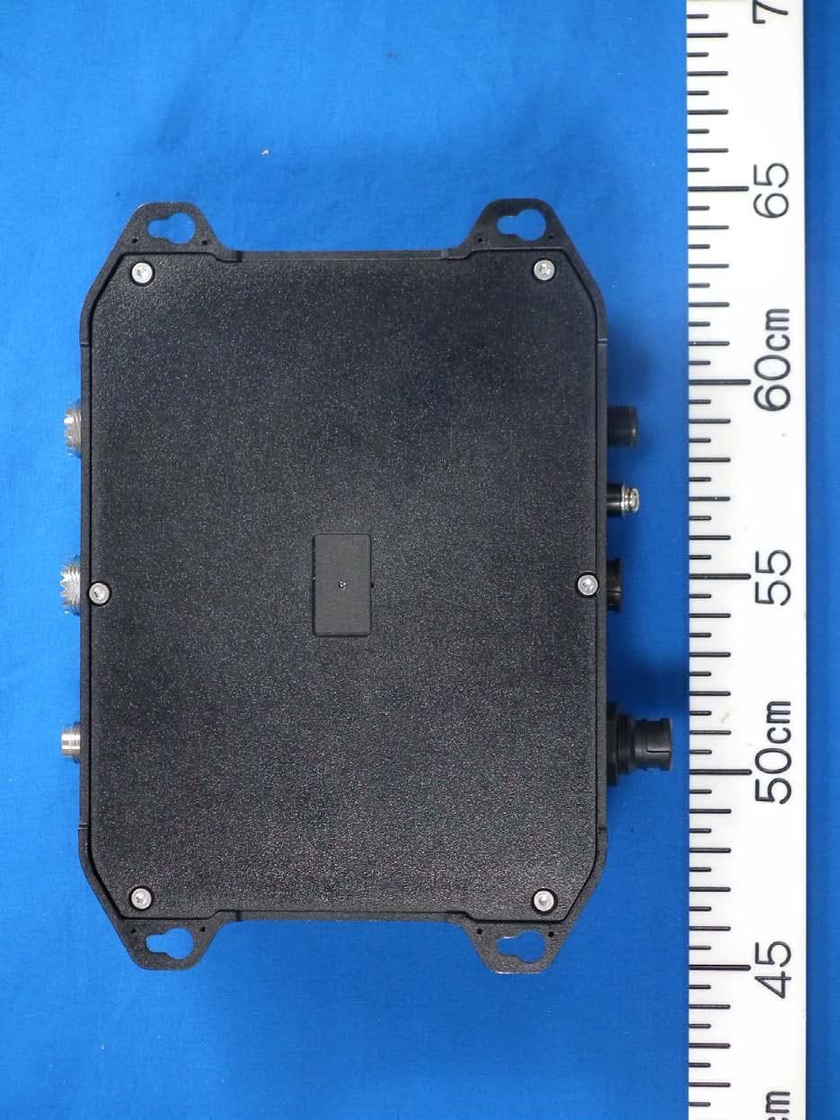
ADB9ZWFA70
May 18, 2020Class B AIS Transponder
Equipment Class
AIS - Automatic Identification Systems