ADB9ZWRTR129Transceiver unit for the radar sensor
Furuno USA Inc
Click to zoom
Application Details
- Equipment Class
- MRD - Marine Radar
- Date of Grant
- May 23, 2021
- Application Purpose
- Original Equipment
- Date of Application
- May 20, 2021
- Equipment Note
- Transceiver unit for the radar sensor
- Frequency Range
- 3020.00000000 - 3080.00000000
- Company
- Furuno USA Inc
- Country
- United States
Documents & Files
Document Text
Text extracted from the exhibit documents filed with the FCC. Open a document above to read the original.
Users Manual
www.furuno.com All brand and product names are trademarks, registered trademarks or service marks of their respective holders. Installation Manual MARINE RADAR Model FAR-2218(-BB)/2228(-BB/-NXT/-NXT-BB)/ FAR-2318/2328(-NXT)/FAR-2238S(-BB/-NXT/-NXT-BB)/ FAR-2338S(-NXT)/2328W/2338SW/2258/2268DS SAFETY INSTRUCTIONS ........................i SYSTEM CONFIGURATION ..................iv EQUIPMENT LISTS..............................xiv 1. INSTALLATION...............................1-1 1.1 Antenna Unit (X-band Radar) .............1-1 1.2 Antenna Unit (S-band Radar) ...........1-10 1.3 Monitor Unit.......................................1-18 1.4 Control Unit .......................................1-19 1.5 Power Supply Unit ............................1-25 1.6 Processor Unit ..................................1-27 1.7 Transceiver Unit................................1-28 1.8 Intelligent Hub (option)......................1-29 1.9 Switching Hub (option)......................1-30 1.10 Junction Box (option) ........................1-30 2. WIRING............................................2-1 2.1 Overview .............................................2-1 2.2 Antenna Unit for X-band, TR-UP Radar......................................2-6 2.3 Antenna Unit for X-band, TR-DOWN Radar .............................2-19 2.4 Antenna Unit for S-band, TR-UP Radar....................................2-25 2.5 Antenna Unit for S-band, TR-DOWN Radar .............................2-37 2.6 Power Supply Unit ............................2-43 2.7 Transceiver Unit................................2-50 2.8 Processor Unit ..................................2-56 2.9 Monitor Unit.......................................2-63 2.10 LAN Signal Converter .......................2-64 2.11 Junction Box (option) ........................2-68 2.12 Intelligent HUB (option).....................2-69 2.13 VDR Connection ...............................2-69 3. ADJUSTMENTS ..............................3-1 3.1How to Open the Radar Installation Menu..3-3 3.2 How to Align the Heading ...................3-3 3.3 How to Adjust the Sweep Timing ........3-4 3.4 How to Suppress Main Bang ..............3-5 3.5 Other Settings .....................................3-5 3.6 How to Control Charts.......................3-26 4. INPUT/OUTPUT DATA................... 4-1 4.1 Processor Unit ....................................4-1 4.2 Sub Monitor.........................................4-3 APPENDIX 1 JIS CABLE GUIDE ..... AP-1 APPENDIX 2DIGITAL INTERFACE.. AP-2 PACKING LISTS ................................. A-1 OUTLINE DRAWINGS ........................ D-1 INTERCONNECTION DIAGRAMS ..... S-1 The paper used in this manual is elemental chlorine free. ・FURUNO Authorized Distributor/Dealer 9-52 Ashihara-cho, Nishinomiya, 662-8580, JAPAN Printed in Japan All rights reserved. A : NOV . 2017 N21 : MAR. 25, 2021 Pub. No. IME-36520-N21 ( AKMU ) FAR-2xx8 series 0 0 0 1 9 8 1 0 4 1 2 i SAFETY INSTRUCTIONS Wear a safety belt and hard hat when working on the antenna unit. Serious injury or death can result if someone falls from the radar antenna mast. The installer must read the applicable safety instructions before attempting to operate or install the equipment. Indicates a potentially hazardous situation which, if not avoided, will result in death or serious injury. DANGER Indicates a potentially hazardous situation which, if not avoided, could result in death or serious injury. WARNING Indicates a potentially hazardous situation which, if not avoided, can result in minor or moderate injury. CAUTION Warning, Caution Prohibitive Action Mandatory Action DANGER Construct a suitable service platform from which to install the antenna unit. Serious injury or death can result if someone falls from the radar antenna mast. Do not open the equipment. This equipment uses high voltage electricity which can shock, burn or cause serious injury. Only qualified personnel can work inside the equipment. WARNING Turn off the power at the mains switchboard before beginning the installation. Fire, electrical shock or serious injury can result if the power is left on or is applied while the equipment is being installed. Be sure that the power supply is compatible with the voltage rating of the equipment. Connection of an incorrect power supply can cause fire or damage the equipment. Attach protective earth securely to the ship's body. The protective earth (grounding) is required for the AC power supply to prevent electrical shock. WARNING Use only the specified power cable. Fire or damage to the equipment can result if a different cable is used. Do not install the units (other than the antenna unit) in a dusty environment, or one where the units may get wet from rain or water splash. Dust or water in the units can result in fire, electrical shock, or damage to the equipment. SAFETY INSTRUCTIONS ii Radio Frequency Radiation Hazard *: The following numerical values, shown in the antenna types, indicate antenna length. [12]: 4 ft, [20]: 6.5 ft, [24]: 8 ft, [30]: 10 ft, [36]: 12 ft **: Unavailable on IMO-type radars FAR-2218(-BB) FAR-2318 RTR-105 (12 kW) RTR-111 (250 W) RTR-106 (25 kW) RTR-108 (25 kW) RTR-107 (30 kW) RTR-109 (30 kW) XN12CF XN20CF XN24CF FAR-2228(-BB) FAR-2328 FAR-2338S The radar antenna emits electromagnetic radio frequency (RF) energy which can be harmful, particularly to your eyes. Never look directly into the antenna aperture from a close distance while the radar is in operation or expose yourself to the transmitting antenna at a close distance. Distances at which RF radiation level of 100, 50 and 10 W/m 2 are given in the table below. If the antenna unit is installed at a close distance in front of the wheel house, your administration may require halt of transmission within a certain sector of antenna revolution. See the installation manual for how to manage blind sectors. XN12CF XN20CF XN24CF 0.6 m 0.4 m 0.3 m 1.3 m 1.0 m 0.7 m 1.4 m 0.9 m 0.6 m 2.7 m 1.7 m 1.3 m 4.4 m 3.0 m 2.5 m 9.5 m 6.8 m 5.…
Text truncated - open the document above for the full version.
Users Manual
EQUIPMENT LISTS xxiv radar’s specification. Refer to the following table to confirm your category. The radar category de- pends on the installed monitor. For BB type, a monitor unit meeting the category requirements of IMO must be prepared by the user. CategoryRadar typeANT. rotation speed CAT 1FAR-2318, FAR-2328, FAR-2328W, FAR-2338S, FAR-2338SW, FAR-2338-NXT 24 rpm CAT 1HSame models as above42 rpm CAT 2FAR-2218, FAR-2228, FAR-2238S, FAR-2238S-NXT24 rpm CAT 2HSame models as above42 rpm CAT 3FAR-2218, FAR-2228, FAR-2238S, FAR-2238S-NXT 24 rpm 1-1 1.INSTALLATION 1.1Antenna Unit (X-band Radar) 1.1.1Installation Considerations • The Antenna Unit is generally installed either on top of the wheelhouse or on the radar mast, on a suitable platform. Locate the Antenna Unit in an elevated position to permit maximum target visibility. • A line of sight from the Antenna Unit to the bow of the ship must hit the surface of the sea in not more than 500 m or twice the ship’s length, depending whichever val- ue is smaller, for all load and trim conditions. • BS/CS broadcast equipment may be subject to interference from radar waves. For BS/CS antenna installation, adjust the height and installation position of the BS/CS antenna to avoid interference from radars. • Install the Antenna Unit so that any blind sectors caused by objects (mast, etc.) are kept to a minimum. A blind sector must not exist in arc of the horizon from right ahead to 22.5° aft of the beam to either side (see the figure below). Also, individual blind sectors of more than 5°, or the total arc of both blind sectors of more than 20°, must not occur in the remaining arc (Figure 2). Note that any two blind sectors sep- arated by 3° or less are regarded as one sector. • Do not install the antenna where extreme winds may strike the port and starboard sides of the antenna. NOTICE Do not apply paint, anti-corrosive sealant or contact spray to coating or plastic parts of the equipment. Those items contain organic solvents that can damage coating and plastic parts, especially plastic connectors. less than 500 m or twice the ship's length Figure 1Figure 2 less than 3° 22.5° 22.5° 270° 90° a, b, c: less than 5° respectively a+b+c+: less than 20° a, b, c: less than 5° respectively a+b+c+: less than 20° 1. INSTALLATION 1-2 • Install the Antenna Unit away from interfering high-power energy sources and TX radio antennas. • Keep the lower edge of the Antenna Unit above the safety rail by at least 500 mm. • Install two Antenna Units as shown in the figure below. • No funnel, mast or derrick shall be within the vertical beamwidth of the Antenna Unit in the bow direction, especially zero degree ±5°, to prevent blind sectors and false echoes on the radar picture. • It is rarely possible to place the Antenna Unit where a completely clear view in all directions is available. Therefore, determine the angular width and relative bearing of any shadow sectors for their influence on the radar at the first opportunity after fitting. • Locate the antenna of an EPFS clear of the radar antenna to prevent interference to the EPFS. A separation of more than two meters is recommended. • A magnetic compass will be affected if the Antenna Unit is placed too close to the compass. Observe the compass safe distances on page ii to prevent interference to a magnetic compass. • Do not paint the radiator aperture, to ensure proper emission of the radar waves. • Ground the unit with the ground wire (supplied). • Deposits and fumes from a funnel or other exhaust vent can affect the aerial perfor- mance and hot gases may distort the radiator portion. Do not install the Antenna Unit where the temperature is more than 55 °C. • Leave sufficient space around the unit for maintenance and servicing. See the An- tenna Unit outline drawing for recommended maintenance space. • For X-band radar, an antenna switch is pro- vided on the chassis to stop the antenna. Make sure the mounting location provides easy access to the switch. more than 20° more than 1 m more than 20° more than 1 m X-band radarS-band radar ANT MOTOR SW 1. INSTALLATION 1-3 • For X-band radar, if it is necessary to lay down the radiator before you fasten it to the Antenna Unit, lay it down with the wave- guide up, to prevent dam- age to the cylinder that surrounds the waveguide. • If the de-icer is installed, a two-pole breaker (supplied locally) must also be installed. Note: For more information, please refer to IMO SN/Circ.271 "Guidelines for the in- stallation of shipborne radar equipment. 1.1.2FAR-2x18/2x28/2x38 Radars How to assemble the Antenna Unit The Antenna Unit consists of the antenna radiator and the Antenna Unit chassis, and they are packed separately. Fasten the antenna radiator to the Antenna Unit chassis as follows: 1. Coat the hatched area shown in the figure in step 2 with the supplied adhesive. 2. Remove the protective waveguide cap from the waveguide on the radiator brack- et. 3. Pass the Gasket (03-182-3186, supplied) to six sets of the Antenna fixing bolts (03-182-4188, supplied, w/two flat washers), and then coat the threads of the An- tenna fixing bolts with the supplied adhesive. Set the radiator on the radiator bracket. Lay down radiator with waveguide facing upward. Waveguide Cylinder Do not apply the adhesive to these locations. Remove this cap BEFORE fastening the radiator. Hacth: Adhesive Radiator bracket REAR view Radiator bracket Antenna Fixing Bolt (w/ two flat washers) Flat washers Gasket Coat with adhesiveCoat with adhesive Radiator BracketRadiator Bracket 1. INSTALLATION 1-4 4. Fasten the antenna radiator to the radiator bracket with the six sets of Antenna fixing bolts. Fasten the bolts in the order shown in the figure to the right. The torque must be 15.0 N•m. 5. Coat the Antenna fixing bolts fixed at step 4 with the supplied adhesive as shown in the right figure. How to hoist the Antenna Unit The Antenna Unit may be assembled before hoisting it to the mounting platform. At- tach lifting…
Text truncated - open the document above for the full version.
Users Manual
1. INSTALLATION 1-25 2. Remove the cable clamp, then remove the cable. 3. Pass the cable through the hole in the figure shown in the figure to the right, then clamp the copper part of the cable with the cable clamp removed at step 1. Note: If the RCU-016 is con- nected in series with RCU- 015, connect J522 instead of J521. 4. Close the back cover of RCU- 016. 1.5Power Supply Unit This unit can be installed on a bulkhead, wall or on the floor. 1.5.1Installation considerations Keep in mind the following points when selecting a location. • Locate the Processor Unit away from heat sources because of heat that can build up inside the cabinet. • Select a location where the vibration is minimal. • Locate the equipment away from places subject to water splash and rain. • Leave sufficient space at the sides and rear of the unit to facilitate maintenance. • A magnetic compass will be affected if the Processor Unit is placed too close to the magnetic compass. Observe the compass safe distances in the SAFETY IN- STRUCTIONS to prevent interference to a magnetic compass. J52 4 J521 Screw (M3×8) Bottom of the unit Screw (M4×8) Remove the cable clamp .Remove the cable clamp . J524 J521 Hole to pass the cable. J522 (for connection with RCU-015 ) 1. INSTALLATION 1-26 • Install the Processor Unit on the floor, or on a bulkhead referring to the following di- rections. For bulkhead, the cable entry must face the deck. • Connect the ground wire (IV-8sq, local supply) between the earth terminal on the chassis and the ship’s earth, using the supplied crimp-on-lug FV2-4 BLU. 1.5.2How to install the Power Supply Unit Use four bolts (M6, local supply) to fasten the Power Supply Unit. For bulkhead mounting, fasten two bolts for the lower notches, leaving 5 mm of thread exposed from the bolt head. Set the notches of the Power Supply Unit on the two bolts, then fas- ten two bolts for the upper bolt holes. Then secure the Power Supply Unit in place with all four bolts fastened tight- ly. Note: For bulkhead installations, the cable entry must face the deck. : Cable entry Installation on a bulkhead Installation on a floor OK OK Notches Bolt holes 1. INSTALLATION 1-27 1.6Processor Unit This unit can be installed on a bulkhead, wall or on the floor. 1.6.1Installation considerations Keep in mind the following points when selecting a location. • Locate the Processor Unit away from heat sources because of heat that can build up inside the cabinet. • Select a location where the vibration is minimal. • Locate the equipment away from places subject to water splash and rain. • Leave sufficient space at the sides and rear of the unit to facilitate maintenance. • A magnetic compass will be affected if the Processor Unit is placed too close to the magnetic compass. Observe the compass safe distances in the SAFETY IN- STRUCTIONS to prevent interference to a magnetic compass. • Allow for a service clearance of 100 mm in front of the vent hole (front and rear sides). • Install the Processor Unit on the floor, or on a bulkhead with the following direction. For bulkhead, the cable entry must face the deck. Front view 䠄Cable entrance side䠅 Rear view : Vent hole : Cable entry Installation on a bulkhead Installation on a floor OK OK 1. INSTALLATION 1-28 • Connect the ground wire (IV-8sq, local supply) between the earth terminal on the chassis and the ship’s earth, using the supplied crimp-on-lug FV2-M3 BLU. 1.6.2How to install the Processor Unit Use four bolts (M6, local supply) to fasten the Processor Unit. For bulkhead mounting, fasten two bolts for the lower notches, leaving 5 mm of thread exposed from the bolt head. Set the notches of the Proces- sor Unit on the two bolts, then fasten two bolts for the upper bolt holes. Then secure the Processor Unit in place with all four bolts fastened tight- ly. Note: For bulkhead installations, the cable entry must face the deck. 1.7Transceiver Unit The transceiver unit is required for TR-DOWN Radar. Installation considerations Keep in mind the following points when selecting a location. • Locate the unit away from heat sources because of heat that can build up inside the cabinet. • Locate the equipment away from places subject to water splash and rain. • Leave sufficient space at the sides and rear of the unit to facilitate maintenance. • Determine the location considering the length of the cable between the transceiver unit and the Antenna Unit and the cable between the transceiver unit and the Power Supply Unit. • A magnetic compass will be affected if the transceiver unit is placed too close to the magnetic compass. Observe the compass safe distances in the SAFETY IN- STRUCTIONS to prevent interference to the compass. • Be sure to connect the ground wire (between the earth terminal on the chassis and the ship’s earth). How to mount the transceiver unit Fix the unit to the mounting location with M6 bolts or 6 coach screws. See the outline drawing for mounting dimensions. Notches Bolt holes 1. INSTALLATION 1-29 1.8Intelligent Hub (option) Use the optional Intelligent Hub HUB-3000 to connect gateway network equipment. Do not connect this network to the shipborne LAN network. Further, do not connect a PC to this network, other than for maintenance. Installation considerations Keep in mind the following considerations when selecting a location. • Locate the hub away from heat sources because of heat that can build up inside the cabinet. • Select a location where the vibration is minimal. • Locate the hub away from places subject to water splash and rain. • Be sure to connect a ground (between the earth terminal on the hub and the ship’s earth). • Leave sufficient space at the sides and rear of the unit to facilitate maintenance. • A magnetic compass will be affected if the hub is placed too close to the magnetic compass. Observe the compass safe distances in the SAFETY INSTRUCTIONS to prevent interference to a magnetic compass. How to install the Intelligent Hub 1. Use two binding screws (M36, sup…
Text truncated - open the document above for the full version.
Users Manual
2. WIRING 2-16 2.2.3How to connect the cables for X-band radar (TR-UP, FAR-2258) Some parts or wiring have been omitted from the illustrations for clarity. 1. Loosen 12 bolts from both covers to remove the covers. Note 1: If the performance monitor is installed, the cable for the performance monitor is connected between the cover for the RF unit side and the RF-TB Board in the Antenna Unit. Open the cover slowly to prevent damage to the cable and connector. Note 2: Both covers have the safety chains to pre- vent falling covers. 2. Disconnect the motor drive connectors (J917, J918) and the BP connector (J911) from the RF-TB Board. If the performance monitor is installed, disconnect the per- formance monitor connector (J916). Front (Nameplate side) Front (Nameplate side) Rear (Cable entry side) Rear (Cable entry side) 12 places on both covers. Covers RF unit sideRF unit sideMotor sideMotor side Safety chain RF unit sideRF unit side J917J917 J918J918 J916J916 J911J911 RF-TB board (03P9665) 2. WIRING 2-17 3. Unfasten the two bolts circled in the figure below to enable removal of the RF unit. Then, pull RF unit to remove it with the handle. To move the RF unit, use two han- dles on the RF unit. Note: The magnetron in the transceiv- er module will demagnetize if it con- tacts ferrous material. When dismounting the transceiver module, lay it on its side or on top of non-ferrous material as shown in the figure to the right. 4. Unfasten the cable glands for the an- tenna and power cables on the rear side and remove the gasket, three flat wash- ers and remove the protector of each entrance. 5. Slide the flat washers and gasket onto the cables as shown in the figure below. HandleHandle HandleHandle RF unitRF unit RF unit sideRF unit side Transceiver module (magnetron inside) Height more than 5 cm Non-ferrous block Rear sideRear side Cable entry for antenna cable Cable entry for antenna cable Cable entry for power cable Cable entry for power cable *: For the cable without armor GlandGland Outer SheathOuter Sheath Gasket (Set on the outer sheath) Gasket (Set on the outer sheath) Inner SheathInner Sheath Shield lineShield line Flat washerFlat washer Armor*Armor* The shield line should be wound once on the flat washer. The shield line should be wound once on the flat washer. Flat washers onto outer sheathFlat washers onto outer sheath Cable entry Cable entry Shield lineShield lineFlat washerFlat washer 2. WIRING 2-18 6. Push the flat washer against the armor then sandwich in the armor between two flat washers. 7. Trim the armor so that it does not extend past the flat washers. 8. Pass the antenna and power cables through each cable entrance and attach the appropriate connectors to the appropriate cables. For how to connect the cables to WAGO connector, see "WAGO connector" on page 2-5. For pin arrangement, see the interconnection diagram at the back of this manual. Note: A terminal opener is provided on the RF-TB Board. Motor power cable 1) Pass the motor power cable as follows: 2) Connect the wires of the motor power cable to the Terminal board TB901 on the front side through the appropriate wiring clamps, according to wiring stick- er. Antenna cable 1) Pass the antenna cable as follows: 2) Connect the wires of the antenna cable to the appropriate WAGO connectors (pre-attached on the RF-TB board). Coaxial cable: TB902 on the TNC Junction Box, passing over the slide rail. Signal lines: TB801, TB802 and TB803, passing over the slide rail. Shield lines: Wing bolt, passing under the slide rail. Front sideFront side TB901TB901 1 2 3 RED BLK WHT MOTOR_H GND MOTOR_C TB901TB901 Pass through the wiring clamps. Pass through the wiring clamps. RF unit sideRF unit side TB803TB803 TB801TB801 TB802TB802 RF-TB board (03P9665) Wing bolt Shield lines • Signal lines • Coaxial cable Slide rail 2. WIRING 2-19 3) Remove the TNC junction box from the RF unit and then connect the coaxial cable of the antenna cable to the BNC case. 4) Re-mount the TNC junction box to the RF unit. 9. Apply the supplied adhesive to the threads of the cable glands, and then fasten it tightly with the hook spanner. Note: Use the wrench of the correct size referring to cable gland size below. If you do not have the hook spanner, contact your dealer. • Gland for the antenna cable: 50 • Gland for the motor cable: 42 10. Re-mount the RF unit then reconnect the motor drive connectors (J917, J918) and the BP connector (J911) to the RF-TB Board, referring to step 2 on page 2-16. Note: When mounting the RF unit, take care not to pinch the power cable with the RF unit. The power cable can be damaged. 11. If required, reconnect the performance monitor connector (J916). 12.Check that the gasket on both covers are seated properly, then close the cov- ers. The torque for the fixing bolts must be 28.0 N•m. 2.3Antenna Unit for X-band, TR-DOWN Radar 2.3.1How to fabricate the cables Three cables are connected to the Antenna Unit: the serial cable from the transceiver unit, waveguide, and de-icer power cable (option). For how to connect the WAGO connector, see "WAGO connector" on page 2-5. TTYCYSLA-10 (for serial cable) Clamp the armor with the cable clamp. RF unitRF unit TNC junction boxTNC junction box Fasten conductor with screw. Fasten conductor with screw. Fasten shield with clamp.Fasten shield with clamp. 14141414 55 14141414 55 Loosen two screws. Folded shield* on the sheath. Fabricated coaxial cable *: For 03CA00099 cable, do not fold the shield as shown in the figure to the right. 2. WIRING 2-20 DPYCY-1.5 (for the optional de-icer) • Before beginning any work on the Antenna Unit, turn off the breaker for the de-icer at the mains switchboard. (Turning off the display unit has no effect.) • The de-icer activates when the temperature becomes 0 °C, and shuts down when the temperature reaches 5 °C. Clamp the armor with the cable clamp. Flexible waveguide The connector at the antenna side is pre-attached to the flexible waveguide. The bending radius shown be…
Text truncated - open the document above for the full version.
Users Manual
2. WIRING 2-33 14.For DE-ICER INSTALLATION, connect the de-icer power cable the de-icer board 03P9573 attached on the front cover. If the de-icer is not provided, go to step 12. 1) Wrap the supplied spiral tube around the de-icer power cable, starting from the crimp-on lugs. Set a locking wire saddle (supplied) at location (6) shown in the following figure. Pass the de-icer power cable through the locking wire saddles (1) to (6) and it to the front side. 2) Pass the de-icer power cable through the cable band. Connect the cable to TB901 on the DE-ICER board (03P9573), using the supplied crimp-on lugs. 3) Set the Voltage Setting switch according to the power source for the de-icer; 115 V or 230 V. The default setting is 230 V. 4) Apply power to the de-icer then press and hold the TEST button for about ten sec- onds. Check that the heater gets hot and then release the TEST button. 5) Set the front cover to the Antenna Unit. Close the open heater and return to its original position.Take care not to hit the heater elements on the chassis or radiator. 6) Fasten the two heater elements to the chassis with the four bolts removed at step 1 on page 2-28. Fasten the base of the heater with two bolts coated with Front cover w/de-icer, inside view DEICER Board (03P9573) TB901 Voltage Setting switch [TEST] button REARREAR Spiral tube TB901 Cable bandCable band 2. WIRING 2-34 the supplied adhesive. Fasten the installation materials to each of the cover bolts. Note: If it is necessary to open the front cover after installing the DE-ICER kit, re- move the de-icer power cable from the locking wire saddle shown in the following figure then detach the cover slowly to prevent damage to the heater. 15. Reconnect the performance monitor connector (J807). 16.Check that the gasket on the front and rear cover is seated properly, then close the covers. The torque for the fixing bolts must be 28.0 N•m. Note: For the de-icer specifications, take care not to hit the heater elements on the chassis or radiator. If the heater hits something, unfasten the fixing screws for the heater to adjust the position of the heater. Then fix the heater again. 2.4.3How to connect the cables for S-band radar (TR-UP, FAR- 2268DS radar) Some parts or wiring have been omitted from the illustrations for clarity. M5 screw coated with adhesive M5 screw coated with adhesive Cover BoltCover Bolt M5 screw (Do not apply adhesive.) M5 screw (Do not apply adhesive.) Fixing Shaft Fixing Shaft SD Heater Fixing Plate SD Heater Fixing Plate FRONTFRONT Remove the de-icer power cable from the locking wire saddle to open the front cover. Remove the de-icer power cable from the locking wire saddle to open the front cover. Gland for power cable Ground terminal Antenna safety switchAntenna safety switch Gland for signal cableGland for signal cable (Not used)(Not used) 2. WIRING 2-35 1. Remove 10 bolts from the cover, right side viewed from the cable entry side, to remove the cover. Note: The safety rope is attached to this cover to prevent falling the cover. 2. Unfasten the cable glands for the antenna and power cables and remove the gas- ket, three flat washers and remove the gland cap of each entrance. The gland caps may be discarded. 3. Slide the flat washers and gasket onto the cables as shown in the figure below. 4. Pass the antenna and power cables through each cable glands and attach the appropriate connectors to the appropriate cables. For how to connect the cables to WAGO connector, see "WAGO connector" on page 2-5. For pin arrangement, see the interconnection diagram at the back of this manual. Note: For the antenna cable, pass the coaxial cable first, and then the signal cables through the cable gland not to bend the coaxial cable as possible. Antenna cable Connect the wires of the antenna cable to the appropriate WAGO connectors (pre-attached on the RF-TB board), according to wiring stickers. Safety ropeSafety rope Cover (Right side, viewed from the cable entry side) Cover (Right side, viewed from the cable entry side) Cable entry side Cable entry side GlandGland Outer SheathOuter Sheath Gasket (Set on the outer sheath.) Gasket (Set on the outer sheath.) Shield lines (Wind once on the flat washer.) Shield lines (Wind once on the flat washer.) Flat washerFlat washer Flat washers onto outer sheathFlat washers onto outer sheath Cable entry Cable entry Cable entrance side TB902TB902 TB801TB801 (A)(A) (B)(B) (C)(C) Shield linesShield lines TB802TB802 TB803TB803 Wiring stickerWiring sticker Wiring stickerWiring sticker 2. WIRING 2-36 • Signal lines: TB801, TB802 and TB803, through the wire saddles (A), (B). • Coaxial cable: TB902 on the TNC Junction Box, through the wire saddles (A), (B). Before connecting the coaxial cable, remove the TNC junction box. After connecting the coaxial cable referring to the figure shown below, re-mount the box to the RF unit. • Shield lines: Wing bolt (C). Motor power cable Connect the wires of the motor power cable to the Terminal board TB901, accord- ing to wiring sticker. 5. Apply the supplied adhesive to the threads of the cable glands, and then fasten it tightly with the hook spanner. Note: Use the wrench of the correct size referring to cable gland size below. If you do not have the hook spanner, contact your dealer. • Gland for the antenna cable: 50 • Gland for the motor power cable: 42 6. Check that the gasket on cover are seated properly, then close the cover. The torque for the fixing bolts must be 15.0 N•m. 7. Seal the cable glands for the power cable with putty. CAUTIOCAUTION High voltage is present at the No. 1 pin of TB801. Miswiring at this pin can damage the antenna unit. Fasten conductor with screw. Fasten conductor with screw. Fasten shield with clamp.Fasten shield with clamp. 14141414 55 14141414 55 Loosen two screws. Folded shield* on the sheath. Fabricated coaxial cable *: For 03CA00099 cable, do not fold the shield as shown in the figure to the right. Cable entrance side Wiring stickerWiring stic…
Text truncated - open the document above for the full version.
Contact Information
Applicant
Bill Haynes(Deep Sea Product Manager)
Test Firm
Labotech International Co., Ltd.Fumiya Ueki
[email protected]+81 798-63-1094
Technical Specifications
| # | Rule Parts | Frequency Range | Power Output | Emission | Tolerance |
|---|---|---|---|---|---|
| 2 | 8 | 3.02 GHz - 3.08 GHz | 60000 W | 56M7P0N | 0.15 % |
Other Applications from Furuno USA Inc
ADB-9ZWRTR137
Feb 18, 2026Transceiver unit for the radar sensor
Equipment Class
MRD - Marine RadarADB9ZWRTR136
Jul 01, 2024Transceiver unit for the radar sensor
Equipment Class
MRD - Marine Radar
ADB9ZWRTR128
Apr 06, 2022Transceiver unit for the radar sensor
Equipment Class
MRD - Marine Radar
ADB9ZWRTR133
Sep 26, 2021Transceiver unit for the radar sensor
Equipment Class
MRD - Marine Radar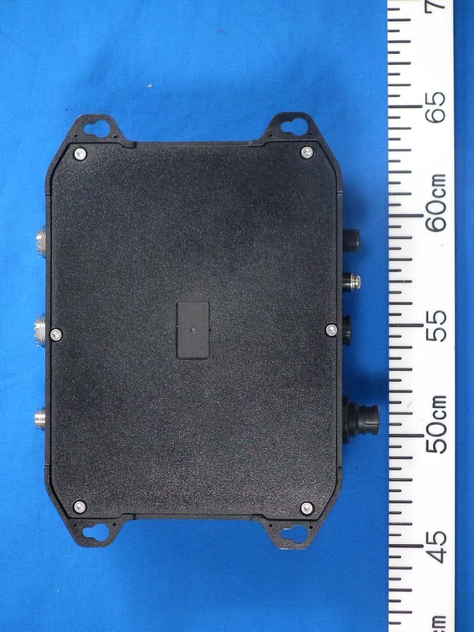
ADB9ZWFA70
May 18, 2020Class B AIS Transponder
Equipment Class
AIS - Automatic Identification Systems