ADB9ZWFA150FA150
Furuno USA Inc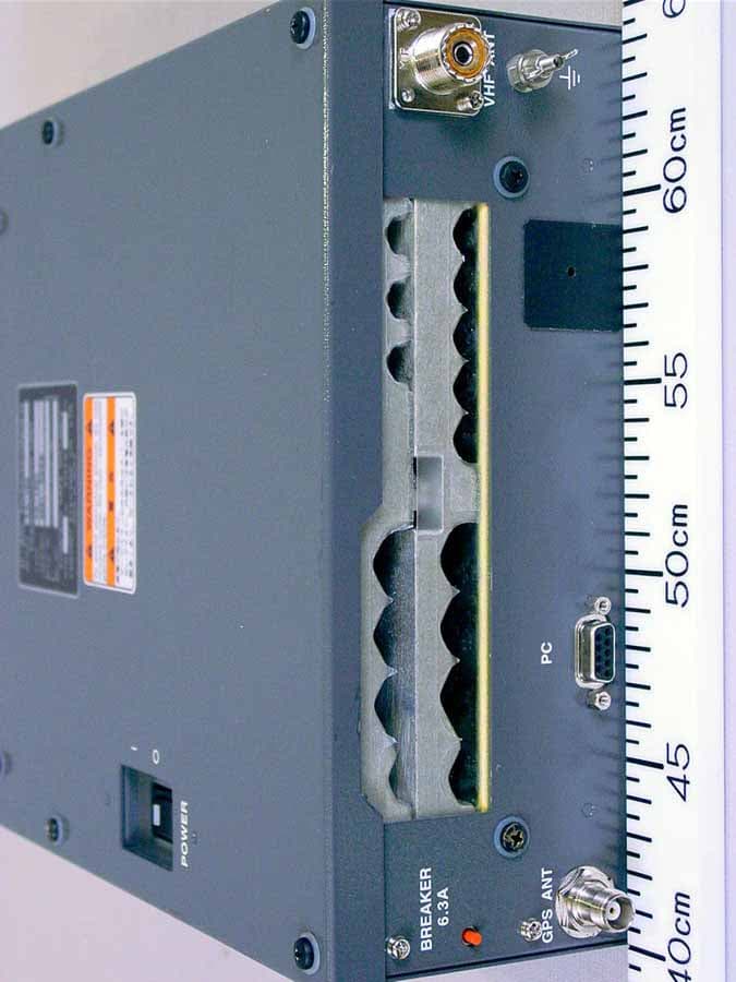
Click to zoom
Application Details
- Equipment Class
- AIS - Automatic Identification Systems
- Date of Grant
- Jul 13, 2005
- Application Purpose
- Original Equipment
- Date of Application
- Jan 06, 2005
- Equipment Note
- FA150
- Frequency Range
- 156.52500000 - 156.52500000
- Company
- Furuno USA Inc
- Country
- United States
Documents & Files
Document Text
Text extracted from the exhibit documents filed with the FCC. Open a document above to read the original.
Users Manual
UAIS TRANSPONDER FA-150 Your Local Agent/DealerYour Local Agent/Dealer 9-52 Ashihara-cho,9-52 Ashihara-cho, Nishinomiya 662-8580, JAPANNishinomiya 662-8580, JAPAN Telephone :Telephone :0798-65-21110798-65-2111 FaxFax0798-65-42000798-65-4200 :: FIRST EDITION :FIRST EDITION :SEPSEP..20042004 Printed in JapanPrinted in Japan All rights reserved.All rights reserved. A1A1::SEPSEP..13, 200413, 2004 Pub. No.Pub. No.OME-44310-A1OME-44310 *00015008100**00015008100* *00015008100**00015008100* ((DAMIDAMI)) FA-150FA-150 * 0 0 0 1 5 0 0 8 1 0 0 ** 0 0 0 1 5 0 0 8 1 0 0 * *OME44310A10**OME44310A10* *OME44310A10**OME44310A10* * O M E 4 4 3 1 0 A 1 0 ** O M E 4 4 3 1 0 A 1 0 * i SAFETY INSTRUCTIONS WARNING Immediately turn off the power at the switchboard if water leaks into the equipment or something is dropped in the equipment. Continued use of the equipment can cause fire or electrical shock. Contact a FURUNO agent for service. Do not disassemble or modify the equipment. Fire, electrical shock or serious injury can result. Do not place liquid-filled containers on the top of the equipment. Fire or electrical shock can result if a liquid spills into the equipment. Immediately turn off the power at the switchboard if the equipment is emitting smoke or fire. Continued use of the equipment can cause fire or electrical shock. Contact a FURUNO agent for service. Make sure no rain or water splash leaks into the equipment. Fire or electrical shock can result if water leaks in the equipment. Do not operate the equipment with wet hands. Electrical shock can result. ELECTRICAL SHOCK HAZARD Do not open the equipment. Only qualified personnel should work inside the equipment. WARNING LABEL A warning label is attached to the AC-DC power supply. Do not remove the label. If the label is missing or damaged, contact a FURUNO agent or dealer about replacement. WARNING To avoid electrical shock, do not remove cover. No user-serviceable parts inside. Name: Warning Label (1) Type: 86-003-1011-1 Code No.: 100-236-231 ii TABLE OF CONTENTS FOREWORD ......................................... iii SYSTEM CONFIGURATION...................v PROGRAM NUMBER ............................vi SYSTEM OVERVIEW ...........................vii 1. OPERATION.................................... 1-1 1.1 Description of Controls ....................... 1-1 1.2 Turning the Power On and Off............ 1-2 1.3 Adjusting Panel Dimmer and Contrast1-4 1.4 Menu Overview................................... 1-5 1.4.1 Menu operating procedure ...... 1-5 1.5 Setting Up for a Voyage ..................... 1-7 1.6 Setting CPA/TCPA ............................ 1-11 1.7 Choosing a Display .......................... 1-12 1.7.1 Plotter display........................ 1-13 1.7.2 Target list (displaying target data) .......... 1-14 1.7.3 Dangerous (target) list........... 1-20 1.7.4 Own ship’s static data ........... 1-20 1.7.5 Own dynamic data display .... 1-22 1.7.6 Alarm status display .............. 1-22 1.8 Messages ......................................... 1-23 1.8.1 Sending a message .............. 1-23 1.8.2 Receiving messages ............. 1-25 1.8.3 Message logs ........................ 1-27 1.9 Regional Operating Channels .......... 1-28 1.9.1 Viewing channels, Tx power . 1-28 1.9.2 Displaying, editing regional operating area status ............. 1-29 1.10 Enabling/Disabling Buzzers, Key Beep ....................................... 1-32 1.11 Long Range Mode ............................ 1-33 1.12 Viewing Initial Settings...................... 1-35 2. MAINTENANCE, TROUBLESHOOTING ..................... 2-1 2.1 Maintenance ...................................... 2-1 2.2 Replacement of Fuse, Resetting Breaker............................................ 2-2 2.2.1 Replacement of fuse............... 2-2 2.2.2 Resetting the breaker ............. 2-2 2.3 Troubleshooting ................................. 2-3 2.4 Diagnostics ........................................ 2-4 2.4.1 Monitor unit test ...................... 2-4 2.4.2 Transponder test..................... 2-5 2.4.3 Power on/off history................ 2-6 2.4.4 Tx on/off history ...................... 2-7 2.5 Alarm Status....................................... 2-8 2.6 Error Messages.................................. 2-9 2.7 GPS Monitor .....................................2-11 2.8 Displaying Sensor Status ................. 2-12 2.9 Restoring Default Settings ............... 2-13 APPENDIX ....................................... AP-1 Menu Tree ................................................AP-1 Parts List ..................................................AP-3 Parts Location ..........................................AP-4 Digital Interface (IEC 61162-1 Edition 2, IEC 61162-2) ........................................AP-6 VHF Channel List ...................................AP-22 SPECIFICATIONS ............................ SP-1 INDEX................................................ IN-1 iii FOREWORD A Word to the Owner of the FA-150 FURUNO Electric Company thanks you for purchasing the FA-150 UAIS Transponder. We are confident you will discover why the FURUNO name has become synonymous with quality and reliability. For over 50 years FURUNO Electric Company has enjoyed an enviable reputation for quality and reliability throughout the world. This dedication to excellence is furthered by our extensive global network of agents and dealers. Your equipment is designed and constructed to meet the rigorous demands of the marine environment. However, no machine can perform its intended function unless properly operated and maintained. Please carefully read and follow the operation and maintenance procedures set forth in this manual. We would appreciate feedback from you, the end-user, about whether we are achieving our purposes. Thank you for considering and purchasing FURUNO. Features The FA-150 is a universal AIS (Automatic Identification System) capable of exchanging navigation and ship data between own ship and other ships or …
Text truncated - open the document above for the full version.
External Photos
Furuno Labotech International Co., Ltd. Document. number: FLI 01-04-021 Revision no.: 1 Date of issue: 15 February 2005 - Page 2 of 24 - 1 External View 1.1 Transponder Unit FA-1501 1.1.1 Top View (Showing Name Plate and Warning Label on Top cover) Furuno Labotech International Co., Ltd. Document. number: FLI 01-04-021 Revision no.: 1 Date of issue: 15 February 2005 - Page 3 of 24 - 1.1.2 Front View Furuno Labotech International Co., Ltd. Document. number: FLI 01-04-021 Revision no.: 1 Date of issue: 15 February 2005 - Page 4 of 24 - 1.2 Monitor unit FA-1502 1.2.1 Front View Furuno Labotech International Co., Ltd. Document. number: FLI 01-04-021 Revision no.: 1 Date of issue: 15 February 2005 - Page 5 of 24 - 1.2.2 Rear View (showing Nameplate) Furuno Labotech International Co., Ltd. Document. number: FLI 01-04-021 Revision no.: 1 Date of issue: 15 February 2005 - Page 6 of 24 - 1.3 GPS Antenna GPA-017S 1.3.1 Front View (Showing Name Plate)
Internal Photos
Furuno Labotech International Co., Ltd. Document. number: FLI 01-04-024 Revision no.: 1 Date of Revised issue: 6 January 2005 - Page S1 of 45 - Photographs of VHF Radio Telephone FM-8800S TABLE OF CONTENTS 1 External View ............................................................................................................................ 2 1.1 Transceiver Unit FM-8800S ...................................................................................................2 1.2 Handset HS-2003 with Bracket .............................................................................................. 5 1.3 Remote Station RB-8810 with Handset HS-8800 (upper) ...................................................... 8 1.4 Remote Station RB-8800 with Handset HS-8800 ................................................................ 11 1.5 Junction Box IF-8810 ........................................................................................................... 14 1.6 DMC Interface IF-8820......................................................................................................... 15 1.7 Handset HS-8800................................................................................................................. 16 2 Internal View............................................................................................................................ 18 2.1 Transceiver Unit FM-8800S ................................................................................................. 18 2.2 Handset HS-2003................................................................................................................. 31 2.3 Remote Station RB-8810 .....................................................................................................33 2.4 Remote Station RB-8800 .....................................................................................................35 2.5 Junction Box IF-8810 ........................................................................................................... 38 2.6 DMC Interface IF-8820......................................................................................................... 40 2.7 Handset HS-8800................................................................................................................. 42 Furuno Labotech International Co., Ltd. Document. number: FLI 01-04-024 Revision no.: 1 Date of Revised issue: 6 January 2005 - Page S2 of 45 - 1 External View 1.1 Transceiver Unit FM-8800S 1.1.1 Top View (Showing Name Plate on Outside Cover) Furuno Labotech International Co., Ltd. Document. number: FLI 01-04-024 Revision no.: 1 Date of Revised issue: 6 January 2005 - Page S3 of 45 - 1.1.2 Rear View Furuno Labotech International Co., Ltd. Document. number: FLI 01-04-024 Revision no.: 1 Date of Revised issue: 6 January 2005 - Page S4 of 45 - 1.1.3 Name Plate Furuno Labotech International Co., Ltd. Document. number: FLI 01-04-024 Revision no.: 1 Date of Revised issue: 6 January 2005 - Page S5 of 45 - 1.2 Handset HS-2003 with Bracket 1.2.1Top View Furuno Labotech International Co., Ltd. Document. number: FLI 01-04-024 Revision no.: 1 Date of Revised issue: 6 January 2005 - Page S6 of 45 - 1.2.2 Bottom View (Handset (Left) and Bracket (Right)) Furuno Labotech International Co., Ltd. Document. number: FLI 01-04-024 Revision no.: 1 Date of Revised issue: 6 January 2005 - Page S7 of 45 - 1.2.3 Name Plate Furuno Labotech International Co., Ltd. Document. number: FLI 01-04-024 Revision no.: 1 Date of Revised issue: 6 January 2005 - Page S8 of 45 - 1.3 Remote Station RB-8810 with Handset HS-8800 (upper) 1.3.1 Top View Furuno Labotech International Co., Ltd. Document. number: FLI 01-04-024 Revision no.: 1 Date of Revised issue: 6 January 2005 - Page S9 of 45 - 1.3.2 Top View (with Handset taken off the hook) Furuno Labotech International Co., Ltd. Document. number: FLI 01-04-024 Revision no.: 1 Date of Revised issue: 6 January 2005 - Page S10 of 45 - 1.3.3 Name Plate Furuno Labotech International Co., Ltd. Document. number: FLI 01-04-024 Revision no.: 1 Date of Revised issue: 6 January 2005 - Page S11 of 45 - 1.4 Remote Station RB-8800 with Handset HS-8800 1.4.1Top View Furuno Labotech International Co., Ltd. Document. number: FLI 01-04-024 Revision no.: 1 Date of Revised issue: 6 January 2005 - Page S12 of 45 - 1.4.2 Top View (with Handset taken off the hook) Furuno Labotech International Co., Ltd. Document. number: FLI 01-04-024 Revision no.: 1 Date of Revised issue: 6 January 2005 - Page S13 of 45 - 1.4.3 Name Plate Furuno Labotech International Co., Ltd. Document. number: FLI 01-04-024 Revision no.: 1 Date of Revised issue: 6 January 2005 - Page S14 of 45 - 1.5 Junction Box IF-8810 1.5.1 Top View (Showing Name Plate) Furuno Labotech International Co., Ltd. Document. number: FLI 01-04-024 Revision no.: 1 Date of Revised issue: 6 January 2005 - Page S15 of 45 - 1.6 DMC Interface IF-8820 1.6.1 Top View (Showing Name Plate) Furuno Labotech International Co., Ltd. Document. number: FLI 01-04-024 Revision no.: 1 Date of Revised issue: 6 January 2005 - Page S16 of 45 - 1.7 Handset HS-8800 1.7.1 Top View Furuno Labotech International Co., Ltd. Document. number: FLI 01-04-024 Revision no.: 1 Date of Revised issue: 6 January 2005 - Page S17 of 45 - 1.7.2 Bottom View (showing Name Plate)
Internal Photos
Furuno Labotech International Co., Ltd. Document. number: FLI 01-04-021 Revision no.: 1 Date of issue: 15 February 2005 - Page 7 of 24 - 2 Internal View 2.1 Transponder Unit FA-1501 2.1.1 Inside Top View (with Top cover removed, showing MOT Board 24P0036 (lower)) Furuno Labotech International Co., Ltd. Document. number: FLI 01-04-021 Revision no.: 1 Date of issue: 15 February 2005 - Page 8 of 24 - 2.1.2 Inside View (with Top cover and shield-covers removed, showing TX Board 24P0032 (upper right), PWR Board 24P0037 (upper left), MOT Board 24P0036 (lower)) Furuno Labotech International Co., Ltd. Document. number: FLI 01-04-021 Revision no.: 1 Date of issue: 15 February 2005 - Page 9 of 24 - 2.1.3 TX Board 24P0032 Front side Furuno Labotech International Co., Ltd. Document. number: FLI 01-04-021 Revision no.: 1 Date of issue: 15 February 2005 - Page 10 of 24 - 2.1.4 TX Board 24P0032 Rear side Furuno Labotech International Co., Ltd. Document. number: FLI 01-04-021 Revision no.: 1 Date of issue: 15 February 2005 - Page 11 of 24 - 2.1.5 PWR Board 24P0037 Front side Furuno Labotech International Co., Ltd. Document. number: FLI 01-04-021 Revision no.: 1 Date of issue: 15 February 2005 - Page 12 of 24 - 2.1.6 PWR Board 24P0037 Rear side Furuno Labotech International Co., Ltd. Document. number: FLI 01-04-021 Revision no.: 1 Date of issue: 15 February 2005 - Page 13 of 24 - 2.1.7 MOT Board 24P0036 Front side Furuno Labotech International Co., Ltd. Document. number: FLI 01-04-021 Revision no.: 1 Date of issue: 15 February 2005 - Page 14 of 24 - 2.1.8 MOT Board 24P0036 Rear side Furuno Labotech International Co., Ltd. Document. number: FLI 01-04-021 Revision no.: 1 Date of issue: 15 February 2005 - Page 15 of 24 - 2.1.9 Inside Bottom View (with Bottom cover removed, showing RX2 Board 24P0033 (upper right), RX1 Board 24P0033 (upper center), DSC Board 24P0034 (upper left) and MAIN Board 24P0035 (lower)) Furuno Labotech International Co., Ltd. Document. number: FLI 01-04-021 Revision no.: 1 Date of issue: 15 February 2005 - Page 16 of 24 - 2.1.10 MAIN Board 24P0035 Front side Furuno Labotech International Co., Ltd. Document. number: FLI 01-04-021 Revision no.: 1 Date of issue: 15 February 2005 - Page 17 of 24 - 2.1.11 MAIN Board 24P0035 Rear side Furuno Labotech International Co., Ltd. Document. number: FLI 01-04-021 Revision no.: 1 Date of issue: 15 February 2005 - Page 18 of 24 - 2.1.12 RX1 (RX2) Board 24P0033 Front side Furuno Labotech International Co., Ltd. Document. number: FLI 01-04-021 Revision no.: 1 Date of issue: 15 February 2005 - Page 19 of 24 - 2.1.13 RX1 (RX2) Board 24P0033 Rear side Furuno Labotech International Co., Ltd. Document. number: FLI 01-04-021 Revision no.: 1 Date of issue: 15 February 2005 - Page 20 of 24 - 2.1.14 DSC Board 24P0034 Front side Furuno Labotech International Co., Ltd. Document. number: FLI 01-04-021 Revision no.: 1 Date of issue: 15 February 2005 - Page 21 of 24 - 2.1.15 DSC Board 24P0034 Rear side Furuno Labotech International Co., Ltd. Document. number: FLI 01-04-021 Revision no.: 1 Date of issue: 15 February 2005 - Page 22 of 24 - 2.2 Monitor unit FA-1502 2.2.1 Inside View (Showing CPU Board 24P0062 Rear side) Furuno Labotech International Co., Ltd. Document. number: FLI 01-04-021 Revision no.: 1 Date of issue: 15 February 2005 - Page 23 of 24 - 2.2.2 CPU Board 24P0062 Front side Furuno Labotech International Co., Ltd. Document. number: FLI 01-04-021 Revision no.: 1 Date of issue: 15 February 2005 - Page 24 of 24 - 2.2.3 CPU Board 24P0062 Rear side
Parts List/Tune Up Info
Furuno Labotech International Report no.: FLI 12-04-068 Form: Q053/01 - Page 31 of 46 - 5.2 Description of the circuitry and devices provided for determining and stabilizing frequency, for suppression of spurious radiation, for limiting modulation, and for limiting power 5.2.1 Block Description This unit FA-150 consists of the Transponder Unit FA-1501, the Monitor Unit FA-1502 and the VHF/GPS Antennas. Figure 5.2.1 Block Diagram of FA-1501 Furuno Labotech International Report no.: FLI 12-04-068 Form: Q053/01 - Page 32 of 46 - VHF separate antenna selection GPS separate antenna selection GPS/VHF combined antenna configuration FAB-151D GSC-001 150M-W2VN GPS-017S GVA-100 + FAB-151D + DB-1 Figure 5.2.2 VHF/GPS Antenna System of FA-150 or Furuno Labotech International Report no.: FLI 12-04-068 Form: Q053/01 - Page 33 of 46 - 5.2.2 Function of major circuits 5.2.2.1 FA-1501 Table 5.2.2.1 Outline of FA-1501 Board name Outline MAIN (24P0035) Consists of MAIN CPU, SUB CPU and its peripheral circuits. Controlling/Processing of AIS (DSC) Communications and I/O interfacing are done by the MAIN CPU. Modulation/Demodulation processing of TDMA/DSC and the analogue-interfacing with the radio parts are done by the SUB CPU. TX (24P0032) GMSK-modulated signal of 45 MHz is input from the MAIN Board and converted into the transmitting frequency and power-amplified. RF Power (HPA) Module U1 (RA35H1516M) amplifies the transmitting signal into 12.5 W. DSC (24P0034) DSC receiving signal is converted into the 36 kHz IF signal. The receiving frequency is CH70: 156.525 MHz. RX1 (24P0033A) AIS receiving signal (TDMA) is converted into the 36 kHz IF signal. Circuit configuration is almost same as those for RX2 Board. Receiving frequencies of CH-A are allocated for RX1 Board. RX2 (24P0033B) AIS receiving signal (TDMA) is converted into the 36 kHz IF signal. Circuit configuration is almost same as those for RX1 Board. Receiving frequencies of CH-B are allocated for RX2 Board. PWR (24P0037) Consists of switching regulators to convert the input voltages of 12 to 24 VDC to output voltages of 13.6 VDC x 2 and 5 VDC for use in each Board. MOT (24P0036) Mother Board for MAIN, RX1, RX2, DSC and PWR Boards. External equipment such as Sensors and Radars are connected to WAGO terminals of the Board. GPS (GN-8093) GPS module for receiving the GPS signal of L1: 1575.42 MHz. Number of receiving channels are 12 parallel (12-satellite tracking). GPS TB (24P0043) For relaying the GPS receiving signal. Furuno Labotech International Report no.: FLI 12-04-068 Form: Q053/01 - Page 34 of 46 - 5.2.2.2 FA-1502 Table 5.2.2.2 Outline of FA-1502 Board name Outline CPU (24P0062) AIS information display (MKD) and the system setting-up. Communications interface of RS-422 with FA-1501 is used with the speed of 38.4 kbps. Furuno Labotech International Report no.: FLI 12-04-068 Form: Q053/01 - Page 35 of 46 - 5.3 FA-1501 Block Description 5.3.1 TX Board (24P0032) Figure 5.3.1 Outline of TX Board The TX Board consists of Reference Oscillator, Frequency converter, TX PLL circuits, Power amplifier and TX/RX Antenna switching circuits. Modulated signal of 45 MHz input from MAIN Board is converted to TX frequency of 150 MHz band, and then amplified into 12.5 W in the HPA module. Reference oscillation frequency of 19.2 MHz is used as the PLL reference frequency for DSC, RX1 and RX2 Boards in addition to TX Board. Furuno Labotech International Report no.: FLI 12-04-068 Form: Q053/01 - Page 36 of 46 - Figure 5.3.2 Block Diagram of TX Board TX 45 MHz modulated signal coming from the MAIN Board is input to U9 via Q15, FL1 and Q12. FL1 is the BPF (Passband width: 10 kHz), and reducing the spurious components included in the TX modulated signal. At U9 TX 45 MHz modulated signal is mixed with the 1st Local oscillation frequency of 201.025 MHz to 207.025 MHz, and then converted to the transmitting frequency of 156.025 MHz to 162.025 MHz. Next stage FL1 is the BPF with the L/C circuits, reducing the spurious components generated by the frequency conversion. U1 is of HPA module (Gain: 30 dB or more) and holds TX Power output of 12.5 W. The output of HPA is of the spurious components attenuated by an LPF made of L/C circuits, and is delivered to the VHF ANT terminal via U2: CM Coupler. Y1 is the 19.2 MHz reference oscillator for the PLL circuits of TX Board, and has an accuracy of 1 ppm, maintaining the VHF transmitting frequency tolerance within 500 Hz. Main Control and Detection signals R VSWR Detects the reflected (reverse) wave voltage (REV) from U2. Activates to transmit the error message “ANT” for announcing the abnormality of the VHF ANT circuits when VSWR reaches 3 or above. MONI Detects the forward wave voltage (FWD) from U2. Furuno Labotech International Report no.: FLI 12-04-068 Form: Q053/01 - Page 37 of 46 - Activates to transmit the error message “TX” for announcing the TX abnormality when no detecting the voltage during TX operation. The LED CR6 goes on during TX operation. PWR REF For setting up the TX Power output to 0, 1, 2 or 12.5 W. The level setting of TX Power output is done by controlling the “BIAS” level of the HPA by using “FWD” signal from U2 and “PWR REF” signal. TX Power is set to 12.5 W by adjusting the Potentiometer R133 when TX Power selection of 12.5 W is made. PTT1, PTT2 PTT1 signal controls U9, and PTT2 controls the HPA peripheral circuits. Both are the control signals for switching TX/RX and have the same control timing. TX UNLOCK Activates to transmit the error message “TX” for announcing the TX abnormality when the TX PLL circuits operation becomes unlocked. Distribution of 19.2 MHz Reference Oscillation frequency of Y1 19.2 MHz Reference Oscillation frequency of Y1 in TX Board is distributed to RX1 and RX2 Boards as the reference of the PLL circuits, and to DSC Board as the reference to generate 2nd Local Oscillation. Frequency adjustment is not necessary for Y1. Figure 5.3.3 Distribution of 19.2 MHz reference oscillation frequen…
Text truncated - open the document above for the full version.
Parts List/Tune Up Info
Furuno Labotech International Report no.: FLI 12-04-068 Form: Q053/01 - Page 25 of 46 - 5 Description of Circuitry and Devices (FCC Rules 2.1033) 5.1 Function of Each Semiconductor or Active Device TX Board: 24P0032 Symbol Component Type Function CR 0001 DIODE(PIN) 1SV268-TD RF switch CR 0002 DIODE(BANDSW) 1SS268-TE85L Protection for RF voltage CR 0003 DIODE(Z) 02CZ2.7Z-TE85L Regulator CR 0004 DIODE(PIN) 1SV268-TD RF switch CR 0005 DIODE(Z) 02CZ4.7Z-TE85L Protection for voltage CR 0006 DIODE(LED) PG1101W-TR LED CR 0007 DIODE(SB) MA2J728 Detection for RF voltage CR 0008 DIODE(SB) MA2J728 For DC bias CR 0009 DIODE(SB) MA2J728 Detection for revers voltage CR 0010 DIODE(SB) MA2J728 Detection for RF voltage CR 0011 DIODE(VC) 1SV229-TPH2 Varactor for VCO CR 0012 DIODE(VC) 1SV229-TPH2 Varactor for VCO FL 0001 FILTER(XTAL) MF45SBD 45.0MHZ Crystal Q 0001 MOS FET(RF) 2SK3074-TE12L RF amp Q 0002 TR(POWER) 2SA1213-Y-TE12L DC switch Q 0003 TR(DIGI) DTC114EKAT146 DC switch Q 0004 TR(DIGI) DTC114EKAT146 DC switch Q 0005 TR(DIGI) DTA114EKAT146 DC switch Q 0006 TR(AF) 2SC2712-Y-TE85L DC switch Q 0007 TR(RF) 2SC3356(M)-T1B RF amp Q 0008 TR(RF) 2SC3356(M)-T1B Buffer amp Q 0009 TR(RF) 2SC3356(M)-T1B VCO Q 0010 FET(RF) PMBFJ310 DC amp Q 0011 TR(RF) 2SA1037AKT146R DC switch Q 0012 TR(RF) 2SC3123 Buffer amp Q 0013 TR(RF) 2SC3123 Buffer amp Q 0014 TR(RF) 2SC3123 Buffer amp Q 0015 TR(RF) 2SC3123 Buffer amp Q 0016 TR(DIGI) DTA114EKAT146 DC switch Q 0017 TR(DIGI) DTC114EKAT146 DC switch Q 0021 TR(RF) 2SA1037AKT146R DC switch Furuno Labotech International Report no.: FLI 12-04-068 Form: Q053/01 - Page 26 of 46 - Symbol Component Type Function Q 0022 TR(RF) 2SA1037AKT146R DC switch Q 0023 TR(DIGI) DTC114EKAT146 DC switch U 0001 IC(P AMP) RA35H1516M-01 RF power amp U 0002 CM COUPLER DCS3D20-0157 U 0003 IC(OPAMP) NJM2904M-T1 DC amp U 0004 IC(OPAMP) NJM2904M-T1 DC amp U 0005 IC(RF AMP) UPC2745TB-E3 RF amp U 0006 IC(RF AMP) UPC2745TB-E3 RF amp U 0007 IC(REG) TA7809F-TE16L Regulator U 0008 IC(REG) TA48L033F-TE12L Regulator U 0009 IC(MIX) NJM2594M-TE1 Mixer U 0010 IC(PLL) LMX2353TMX PLL U 0011 MOS LOG(7SH) TC7SHU04F-TE85L Buffer amp Y 0001 XTAL OSCILLATOR TTS14NSB-A5 19.2MHZ Reference OSC DSC Board: 24P0034 Symbol Component Type Function CR 1 DIODE(SW) 1SS272-TE85L Detection for reverse voltage CR 2 DIODE(PIN) MA555-TX AGC CR 3 DIODE(SB) MA716-TX Detection for RF voltage CR 4 DIODE(PIN) MA555-TX AGC FL 1 XTAL FILTER MF38.3SB 38.364MHZ FL 2 XTAL FILTER MF38.3SB 38.364MHZ Q 1 TR(AF) 2SC2712-Y-TE85L AGC amp Q 3 TR(RF) 2SC5336-T1 RF amp Q 5 TR(RF) 2SC4703-T1 RF amp Q 6 TR(RF) 2SC3123 Buffer amp Q 7 TR(AF) 2SC2712-Y-TE85L IF amp Q 8 TR(RF) 2SC3356(M)-T1B Buffer amp Q 9 TR(RF) 2SC3123 Buffer amp Q 10 TR(RF) 2SC3123 IF amp Q 11 TR(RF) 2SC3123 IF amp Q 14 MOS FET(RF) 2SK882-GR-TE85L IF amp U 1 IC(REG) AN7712SP-E1 Regulator U 2 IC(REG) TA48L033F-TE12L Regulator U 4 IC(OPAMP) M5218AFP-600C IF amp Furuno Labotech International Report no.: FLI 12-04-068 Form: Q053/01 - Page 27 of 46 - Symbol Component Type Function U 5 IC(OPAMP) NJM2904M-T1 DC amp U 6 IC(MIX) NJM2594M-TE1 Mixer U 7 MOS LOG(7SH) TC7SHU04F-TE85L Buffer amp U 8 IC(MIX) CMY210GEGE6327-PBF Mixer Y 1 XTAL OSCILLATOR TTS14NSB-A5 29.54025 MHz 1st local OSC DSC RX1 & RX2 Boards: 24P0033A & 24P0033B Symbol Component Type Function CR 2 DIODE(VC) 1SV229-TPH2 Varactor for VCO CR 3 DIODE(VC) 1SV229-TPH2 Varactor for VCO CR 4 DIODE(SB) MA716-TX Detection for RF voltage CR 5 DIODE(PIN) MA555-TX AGC CR 6 DIODE(SW) 1SS272-TE85L Detection for reverse voltage FL 1 XTAL FILTER MF51.1NB 51.1375MHZ FL 1 XTAL FILTER MF51.2NB 51.2375MHZ FL 2 XTAL FILTER MF51.1SB 51.1375MHZ FL 2 XTAL FILTER MF51.2SB 51.2375MHZ Q 2 TR(RF) 2SC3356(M)-T1B Buffer amp Q 3 TR(RF) 2SC3356(M)-T1B VCO Q 4 TR(AF) 2SC2712-Y-TE85L DC switch Q 5 FET(RF) PMBFJ310 DC amp Q 6 TR(RF) 2SC3123 IF amp Q 7 TR(RF) 2SA1037AKT146R DC switch Q 8 TR(RF) 2SC3123 IF amp Q 9 TR(RF) 2SC3123 Buffer amp Q 10 TR(AF) 2SC2712-Y-TE85L IF amp Q 11 TR(AF) 2SC2712-Y-TE85L AGC amp Q 12 TR(RF) 2SC2412KT146R DC switch Q 13 TR(RF) 2SA1037AKT146R DC switch U 1 IC(MIX) AD831AP Mixer U 2 IC(RF AMP) UPC2745TB-E3 RF amp U 3 IC(RF AMP) UPC2745TB-E3 RF amp U 4 IC(PLL) LMX2353TMX PLL U 5 MOS LOG(7SH) TC7SHU04F-TE85L Buffer amp U 6 MOS LOG(7SH) TC7SHU04F-TE85L Buffer amp Furuno Labotech International Report no.: FLI 12-04-068 Form: Q053/01 - Page 28 of 46 - Symbol Component Type Function U 8 IC(OPAMP) M5218AFP-600C IF amp U 9 IC(REG) TA48L033F-TE12L Regulator U 10 IC(OPAMP) NJM2904M-T1 DC amp U 11 IC(MIX) NJM2594M-TE1 Mixer U 12 IC(REG) TA7809F-TE16L Regulator Y 1 XTAL OSCILLATOR TTS14NSB-A5 25.55075MHz 2nd local OSC Y 1 XTAL OSCILLATOR TTS14NSB-A5 25.60075MHz 2nd local OSC MAIN Board: 24P0035 Symbol Component Type Function CR 0001 DIODE(LED) PG1101W-TR LED CR 0002 DIODE(LED) PG1101W-TR LED CR 0003 DIODE(LED) PG1101W-TR LED CR 0004 DIODE(LED) PG1101W-TR LED CR 0005 DIODE(SW) 1SS226-TE85L CR 0006 DIODE(SW) 1SS226-TE85L CR 0007 DIODE(SW) 1SS226-TE85L CR 0008 DIODE(SW) 1SS226-TE85L Switching CR 0009 DIODE(SW) 1SS226-TE85L Switching CR 0010 DIODE(SB) MA2J728 CR 0011 DIODE(LED) PG1101W-TR LED CR 0012 DIODE(LED) PG1101W-TR LED CR 0013 DIODE(LED) PG1101W-TR LED CR 0014 DIODE(LED) PG1101W-TR LED U 0001 IC(RF AMP) UPC2745TB-E3 Buffer amp U 0002 MOS SDRAM IC42S16100-7T SDRAM U 0003 IC(OPAMP) NJM5532M-TE1 Buffer amp for DSC U 0004 IC(OPAMP) NJM5532M-TE1 Buffer amp for RX1 U 0005 IC(OPAMP) NJM5532M-TE1 Buffer amp for RX2 U 0006 MOS MPU HD6417750RF240 Sub CPU U 0007 MOS AD9834BRU-REEL7 DDS U 0008 MOS SDRAM IC42S16100-7T SDRAM U 0011 IC(RESET) RN5VD28A-TR Reset U 0012 MOS LGC(7W) TC7W14FU-TE12L Schmitt inverter Furuno Labotech International Report no.: FLI 12-04-068 Form: Q053/01 - Page 29 of 46 - Symbol Component Type Function U 0013 IC(AD/DA) AK4528VF AD/DA converter U 0014 IC(AD/DA) AK4528VF AD/DA converter U 0015 IC(D/A) MAX5385EUT-T D/A converter U 0016 MOS LGC(ALVC) 74ALVC32PW OR gate U 0017 MOS LGC(7W) TC7WU04FU-TE12L U 0018 IC(FPGA) XC2S200E-6PQ208C U 0019 IC(A/D) M…
Text truncated - open the document above for the full version.
Test Report
This report shall not be reproduced except in full, without the written approval of Furuno Labotech International Co., Ltd. TECHNICAL INFORMATION TEST REPORT ON THE PERFORMANCE OF Universal Automatic Identification System Trade Name : FURUNO Model : FA-150 Report no.: FLI 12-04-068 Date of issue: November 30, 2004 Furuno Labotech International Co., Ltd. 9-52 Ashihara-cho, Nishinomiya City, Hyogo 662-8580, Japan Tel: +81-798-63-1094 Fax: +81-798-63-1098 Furuno Labotech International Report no.: FLI 12-04-068 Form: Q053/01 - Page 1 of 46 - All tests were performed in Furuno Labotech International Co., Ltd. All data herein contained is true and correct to our best knowledge. Tested by: Katsumi Imamura / Assistant Chief, Technical Section Reviewed by: Takekazu Yokose / Chief Engineer, Technical Section Approved by: Mitsuyoshi Komori / Manager, Technical Section Date: November 30, 2004 Name: Mitsuyoshi Komori Manager, Technical Section Signature: Furuno Labotech International Report no.: FLI 12-04-068 Form: Q053/01 - Page 2 of 46 - * * * * * * C O N T E N T S * * * * * * 1 General Information.............................................................................................................................. 3 2 Identification of Equipment (FCC Rule 2.925).................................................................................... 6 3 Test data................................................................................................................................................ 7 3.1 RF Power Output (FCC Rule 2.1046)..................................................................................................... 7 3.2 Occupied Bandwidth (FCC Rule 2.1049) ............................................................................................... 9 3.3 Spurious Emissions at Antenna Terminals (FCC Rule 2.1051) ........................................................... 14 3.4 Field Strength of Spurious Radiation (FCC Rule 2.1053) .................................................................. 18 3.5 Frequency Stability (FCC Rule 2.1055) ...........................................................…
Text truncated - open the document above for the full version.
Contact Information
Applicant
Bill Haynes(Deep Sea Product Manager)
Technical Specifications
| # | Rule Parts | Frequency Range | Power Output | Emission | Tolerance |
|---|---|---|---|---|---|
| 3 | 8 | 156.525 MHz - 156.525 MHz | 12.5 W | 14K2G2B | 3 ppm |
Other Applications from Furuno USA Inc
ADB-9ZWRTR137
Feb 18, 2026Transceiver unit for the radar sensor
Equipment Class
MRD - Marine RadarADB9ZWRTR136
Jul 01, 2024Transceiver unit for the radar sensor
Equipment Class
MRD - Marine Radar
ADB9ZWRTR128
Apr 06, 2022Transceiver unit for the radar sensor
Equipment Class
MRD - Marine Radar
ADB9ZWRTR133
Sep 26, 2021Transceiver unit for the radar sensor
Equipment Class
MRD - Marine Radar
ADB9ZWRTR129
May 23, 2021Transceiver unit for the radar sensor
Equipment Class
MRD - Marine Radar