ADB9ZWFA170Automatic Identification Systems
Furuno USA Inc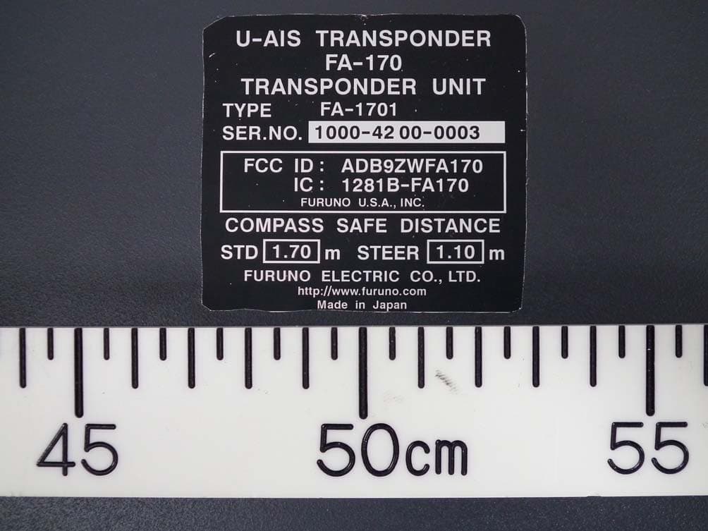
Click to zoom
Application Details
- Equipment Class
- AIS - Automatic Identification Systems
- Date of Grant
- Jan 25, 2016
- Application Purpose
- Original Equipment
- Date of Application
- Jan 18, 2016
- Equipment Note
- Automatic Identification Systems
- Frequency Range
- 156.02500000 - 162.02500000
- Company
- Furuno USA Inc
- Country
- United States
Documents & Files
Document Text
Text extracted from the exhibit documents filed with the FCC. Open a document above to read the original.
Users Manual
www.furuno.com All brand and product names are trademarks, registered trademarks or service marks of their respective holders. Installation Manual CLASS A AIS Model FA-170 PRODUCT NAME: U-AIS TRANSPONDER SAFETY INSTRUCTIONS ................................................................................................ i SYSTEM CONFIGURATION ........................................................................................... ii EQUIPMENT LISTS........................................................................................................ iii 1. MOUNTING.............................................................................................................. 1-1 1.1 How to Install the Antenna Unit(s) .....................................................................................1-1 1.2 How to Install the FA-1702 Monitor Unit ............................................................................1-7 1.3 How to Install the FA-1701 Transponder Unit..................................................................1-12 1.4 How to Install the PR-240 Power Supply (option)............................................................1-13 1.5 How to Install the FA-1703 Pilot Plug Unit (option)..........................................................1-14 2. WIRING.................................................................................................................... 2-1 2.1 Connection Overview.........................................................................................................2-1 2.2 How to Fabricate the Cables..............................................................................................2-2 2.3 Unit Interconnection ...........................................................................................................2-4 2.4 How to Terminate COM ports (For IEC 61162-1/2 signal).................................................2-8 2.5 How to Change the Ship’s Mains Specifications................................................................2-9 3. SETTING AND ADJUSTMENT ............................................................................... 3-1 3.1 How to Set MMSI, IMO No., Name and Call Sign..............................................................3-2 3.2 Inland AIS Specific Settings...............................................................................................3-3 3.3 How to Set GPS Antenna Position.....................................................................................3-5 3.4 How to Enable and Disable Alerts .....................................................................................3-6 3.5 How to Set Up the I/O Ports...............................................................................................3-7 3.6 Network Set Up..................................................................................................................3-8 3.7 SERVICE Menu Operations...............................................................................................3-9 APPENDIX 1 JIS CABLE GUIDE ............................................................................. AP-1 APPENDIX 2 DIGITAL INTERFACE ........................................................................ AP-2 PACKING LISTS ......................................................................................................... A-1 OUTLINE DRAWINGS ................................................................................................ D-1 INTERCONNECTION DIAGRAM ................................................................................ S-1 Z10 (GREG) FA-170 IME-44900-Z10 OCT. 30,2015: i SAFETY INSTRUCTIONS The installer must read the safety instructions before attempting to install this equipment. WARNINGWARNING Be sure that the power supply is compatible with the voltage rating of the equipment. Connection of an incorrect power supply can cause fire or damage the equipment. The voltage rating of the equipment appears on the label above the power connector. CAUTIONCAUTION FA-1703 Pilot Plug unit Indicates a potentially hazardous situation which, if not avoided, could result in death or serious injury. Warning, CautionProhibitive ActionProhibitive Action Indicates a potentially hazardous situation which, if not avoided, can result in minor or moderate injury. WARNING CAUTION ELECTRICAL SHOCK HAZARD Do not open the equipment unless totally familiar with electrical circuits and service manual. Only qualified personnel should work inside the equipment. Turn off the power at the switchboard before beginning the installation. Fire or electrical shock can result if the power is left on. Do not install the equipment where it may get wet from rain or water splash. Water in the equipment can result in fire, electrical shock or damage the equipment. Observe the following compass safe distances to prevent interference to a magnetic compass: Standard compass Steering compass FA-1701 Transponder unit FA-1702 Monitor unit Attach protective earth securely to the ship's body. The protective earth is required to the power supply to prevent electrical shock. 1.70 m1.10 m 0.65 m0.40 m 0.35 m0.30 m GVA-100-T Standard compass Steering compass 0.40 m0.30 m DB-1 0.30 m0.30 m PR-240 0.90 m0.60 m Do not approach the antenna closer than listed below when it is transmitting. The antenna emits radio waves that can be harmful to the human body. RF power density on antenna aperture Distance 100 W/m 2 10 W/m 2 2 W/m 2 0.09 m 0.04 m N/A EquipmentEquipment ii SYSTEM CONFIGURATION GPS/VHF combined antenna GVA-100-T GPS antenna GPA-017S Distributor unit DB-1 VHF antenna VHF antenna Power supply PR-240 100/110/115/200/ 220/230 VAC 1 ø, 50/60Hz 12-24 VDC OR 24 VDC MONITOR UNIT FA-1702 (two units may be connected) External display, NavNet2, NavNet 3D, Pilot plug (FA-1703), Sensor Beacon receiver Alarm system LAN Blue Sign GPS-017S Exposed to the weather GVA-100-T FA-1701 FA-1702 DB-1 PR-240 Exposed to the weather Protec…
Text truncated - open the document above for the full version.
Users Manual
3. SETTING AND ADJUSTMENT 3-6 3.4How to Enable and Disable Alerts You can enable or disable alerts from the [ALERT ENABLE] menu. Disabling an alert in this menu will disable all related alerts for the disabled alert. Note: All alerts are set to [ENABLE] by default. 1. Access the [INITIAL SET] menu, following the procedure outlined in "How to ac- cess the [INITIAL SET] menu" on page 3-1. 2. Select [ALERT ENABLE], then press the ENT/ACK key. Active/unacknowledged alerts are displayed with an alert icon next to the alert ID. 3. Select an alert, then press the ENT/ACK key to enable or disable the alert. Enabled alerts are displayed in green color text, disabled alerts are displayed in gray color text. 4. Press the MENU/ESC key to return to the [INITIAL SET] menu. ALERT ENABLE : BACK: CURSOR MENU : ENABLE/DISABLE ENT WARNING1WARNING2 ENABLE 001014 026 030 029 005 007 009 010 008 011 025 035 032 002 003 004 DISABLEENABLE HI LO 001 :TX MALFUNCTION DISABLE : 8: 0: 0: 9 Cursor selection is highlighted Selected alert’s details Disabled alerts are displayed in gray. 3. SETTING AND ADJUSTMENT 3-7 3.5How to Set Up the I/O Ports 1. Access the [INITIAL SET] menu, following the procedure outlined in "How to ac- cess the [INITIAL SET] menu" on page 3-1. 2. Select [I/O PORT], then press the ENT/ACK key. Note: The figure above shows the default settings for all ports. The available port settings are outlined in the table on the following page. Note 1: When [MODE] is set to [BEACON] or [MONITOR], speed settings are fixed at the default setting. Note 2: For detailed information on data format and related speeds, see "DIGITAL INTERFACE" on page AP-2. Mode definitions PORTMODESPEED (baud) COM1EXT DISPLAY4800, 38400 LONG RANGE4800, 38400 BEACON4800 MONITOR57600 SERVICE4800, 38400 DISABLE- COM2 to COM3Same as COM1.Same as COM1. COM4EXT DISPLAY4800, 38400 LONG RANGE4800, 38400 SENSOR4800, 38400 BEACON4800 MONITOR57600 SERVICE4800, 38400 DISABLE- COM5 to COM6Same as COM4.Same as COM4. SENSOR1SENSORFixed at 4800 DISABLE- SENSOR2 & SENSOR3Same as SENSOR1.Same as SENSOR1. MODEDefinition EXT DISPLAYExternal display (Radar, ECDIS, Pilot plug, etc.) LONG RANGELong range communication device (Inmarsat C, etc.) SENSORGPS, Gyrocompass, ROT, etc. MONITORFor FA-1702 Monitor Unit. BEACONFor Beacon Receiver. SERVICEFor service personnel only. Do not use. DISABLEDisable the port. EXT DISPLAY EXT DISPLAY EXT DISPLAY I / O PORT PORT COM1 MODESPEED 38400baud COM2EXT DISPLAY EXT DISPLAY 38400baud COM3EXT DISPLAY38400baud COM4 SENSOR SENSOR SENSOR 38400baud COM538400baud COM638400baud SENSOR14800baud SENSOR2 4800baud SENSOR3 4800baud : SELECT: CURSOR ENT : BACK ENT 3. SETTING AND ADJUSTMENT 3-8 3.5.1How to set port priority 1. Access the [INITIAL SET] menu, following the procedure outlined in "How to ac- cess the [INITIAL SET] menu" on page 3-1. 2. Select [PORT PRIORITY], then press the ENT/ACK key. 3. Select the sensor whose priority you want to adjust, then press the ENT/ACK key. The [SENSOR PORT] pop up window is displayed. 4. Select the appropriate port, then press the ENT/ACK key. 5. Repeat step 3 to step 4 for other port priorities. 6. Press the MENU/ESC key to return to the [INITAL SET] menu. 3.6Network Set Up 1. Access the [INITIAL SET] menu, following the procedure outlined in "How to ac- cess the [INITIAL SET] menu" on page 3-1. 2. Select [NETWORK], then press the ENT/ACK key. 3. [IP ADDRESS] is selected. Press the ENT/ACK key to set the IP address for the FA-170 within the network. 4. Select and set [SUBNET MASK] and [GATEWAY] in a similar fashion. For NAVNET networks, go to step 5, for other network types, go to step 12. 5. Select [NAVNET PORT], then press the ENT/ACK key. 6. Input the NAVNET port which this unit is connected to, then press the ENT/ACK key. 7. Select [HOST NAME], then press the ENT/ACK key. 8. Input the name for this unit within the NAVNET network. 9. Select [AIS INFO], then press the ENT/ACK key. PORT PRIORITY PRIORITY 1st LL/COG/COG SENSOR1 HDGROT 2ndSENSOR2 3rdSENSOR3 4thCOM4 COM5 COM6 SENSOR3 SENSOR1 SENSOR2 COM6 COM4 COM5 SENSOR3 SENSOR1 SENSOR2 COM6 COM4 COM5 5th 6th : SELECT: CURSOR ENT : BACK ENT Selected item is highlighted in reverse video. SENSOR PORT SENSOR1 SENSOR2 SENSOR3 COM4 COM5 COM6 NETWORK : CURSOR: SELECT 172 . 031 . 024 . 004 255 . 255 . 000 . 000 000 . 000 . 000 . 000 AI0001 ENT : BACK MENU IP ADDRESS SUBNET MASK GATEWAY SFI <SAVE> NETWORK ( NAVNET ) : CURSOR: SELECT 172 . 031 . 024 . 004 255 . 255 . 000 . 000 000 . 000 . 000 . 000 10000 ENT : BACK MENU IP ADDRESS SUBNET MASK GATEWAY NAVNET PORT AIS0HOST NAME ONAIS INFO OFFZDA INFO OFFGPS INFO [ OUTPUT AT STARTUP ] <SAVE> Standard network settings screen.NAVNET network settings screen. 3. SETTING AND ADJUSTMENT 3-9 10. Select [ON] to enable AIS data output to the NAVNET network when this unit is turned on. Select [OFF] to disable AIS data output when this unit is turned on. 11. Set [ZDA INFO] and [GPS INFO] in the same manner as [AIS INFO], then go to step 14. 12. Select [SFI], then press the ENT/ACK key. 13. Set the [SFI] (System Function ID), then press the ENT/ACK key. 14. Confirm the settings are correct, then select [<SAVE>] and press the ENT/ACK key. A confirmation pop up is displayed. Note: If no changes are made to the settings, [<SAVE>] is not selectable. 15. Select [NO] to change the settings further. Select [YES] to accept the new set- tings, the unit now shuts down automatically to apply the new settings. When the unit is shut down, press the power key to restart the unit. 3.7SERVICE Menu Operations The [SERVICE] menu is password protected. Contact FURUNO for password details. The following items require access to the SERVICE for initial setup: • ALERT MODE settings • Network protocol settings • Restore Factory settings 3.7.1How to access the SERVICE menu 1. From the [MAIN] menu, select [SERVICE], then press the ENT/ACK key. The password input pop up appears. 2. Input the password then press the ENT/ACK key. 3.7.2How to …
Text truncated - open the document above for the full version.
Users Manual
FA-170 OPERATOR'S MANUAL www.furuno.com Model CLASS A AIS PRODUCT NAME: U-AIS TRANSPONDER Z10 (GREG) FA-170 OME-44900-Z10 OCT. 30,2015: i IMPORTANT NOTICES General • The operator of this equipment must read and follow the descriptions in this manual. Wrong op- eration or maintenance can cancel the warranty or cause injury. • Do not copy any part of this manual without written permission from FURUNO. • If this manual is lost or worn, contact your dealer about replacement. • The contents of this manual and equipment specifications can change without notice. • The example screens (or illustrations) shown in this manual can be different from the screens you see on your display. The screens you see depend on your system configuration and equip- ment settings. • Save this manual for future reference. • Any modification of the equipment (including software) by persons not authorized by FURUNO will cancel the warranty. • All brand and product names are trademarks, registered trademarks or service marks of their respective holders. How to discard this product Discard this product according to local regulations for the disposal of industrial waste. For disposal in the USA, see the homepage of the Electronics Industries Alliance (http://www.eiae.org/) for the correct method of disposal. How to discard a used battery Some FURUNO products have a battery(ies). To see if your product has a battery, see the chapter on Maintenance. Follow the instructions below if a battery is used. Tape the + and - terminals of battery before disposal to prevent fire, heat generation caused by short circuit. In the European Union The crossed-out trash can symbol indicates that all types of batteries must not be discarded in standard trash, or at a trash site. Take the used batteries to a battery collection site according to your national legislation and the Batteries Directive 2006/66/EU. In the USA The Mobius loop symbol (three chasing arrows) indicates that Ni-Cd and lead-acid rechargeable batteries must be recycled. Take the used batteries to a battery collection site according to local laws. In the other countries There are no international standards for the battery recycle symbol. The number of symbols can increase when the other countries make their own recycle symbols in the future. Cd Ni-CdPb ii SAFETY INSTRUCTIONS The operator must read the safety instructions before attempting to operate this equipment WARNING Immediately turn off the power at the switchboard if water leaks into the equipment or something is dropped in the equipment. Continued use of the equipment can cause fire or electrical shock. Contact a FURUNO agent for service. Do not disassemble or modify the equipment. Fire, electrical shock or serious injury can result. Do not place liquid-filled containers on the top of the equipment. Fire or electrical shock can result if a liquid spills into the equipment. Use the proper fuse. Use of the wrong fuse can cause fire or permanent damage to the equipment. ELECTRICAL SHOCK HAZARD Do not open the equipment. Only qualified personnel should work inside the equipment. WARNING To avoid electrical shock, do not remove cover. No user-serviceable parts inside. Unit: PR-240 Power Supply Name: Warning Label (1) Type: 86-003-1011-3 CodeNo.: 100-263-233-10 WARNING LABEL A warning label is attached to the AC-DC power supply. Do not remove the label. If the label is missing or damaged, contact a FURUNO agent or dealer about replacement. Mandatory Action Prohibitive Action WARNING CAUTION Warning, Caution Indicates a potentially hazardous situation which, if not avoided, could result in death or serious injury. Indicates a potentially hazardous situation which, if not avoided, can result in minor or moderate injury. WARNING Immediately turn off the power at the switchboard if the equipment is emitting smoke or fire. Continued use of the equipment can cause fire or electrical shock. Contact a FURUNO agent for service. Make sure no rain or water splash leaks into the equipment. Fire or electrical shock can result if water leaks in the equipment. Do not operate the equipment with wet hands. Electrical shock can result. The glass of an LCD panel breaks easily. Handle the LCD carefully. Injury can result if the glass breaks. About the TFT LCD The TFT LCD is constructed using the latest LCD techniques, and displays 99.99% of its pixels. The remaining 0.01% of the pixels may drop out or blink, however this is not an indication of malfunction. Do not approach the antenna closer than listed below when it is transmitting. The antenna emits radio waves that can be harmful to the human body. RF power density on antenna apertureDistance 100 W/m 2 10 W/m 2 2 W/m 2 0.09 m 0.04 m N/A iii SYSTEM OVERVIEW System overview The Automatic Identification System (AIS) was originally developed to aid the Vessel Traffic Ser- vices (VTS) by use of a VHF transponder working on Digital Selective Call (DSC) at VHF CH70, and is still in use along the UK coastal areas and others. Some time later the IMO developed a Universal AIS using the new sophisticated technology called Self-Organized Time Division Multi- ple Access (SOTDMA) based on a VHF Data Link (VDL). The system operates in three modes – autonomous (continuous operation in all areas), assigned (data transmission interval remotely controlled by authority in traffic monitoring service) and polled (in response to interrogation from a ship or authority). It is synchronized with GPS time to avoid conflict among multiple users (IMO minimum 2000 reports per minute and IEC requires 4500 re- ports on two channels). The VHF channels 87B and 88B are commonly used and in addition there are local AIS frequencies. Shipborne AIS transponders exchange various data as specified by the IMO and ITU on either frequency automatically set up by the frequency management telecom- mand received by the DSC receiver on ship. AIS system Not all ships carry AIS The Officer of the Watch (OOW) should always be aware that…
Text truncated - open the document above for the full version.
Users Manual
2. INLAND AIS OPERATION 2-6 12. Select [BLUE CONES], then press the ENT/ACK key. The pop up window shown below appears. Depending on the cargo, up to four “cones” have to be shown on the mast, in day- light with cones and nighttime with blue lights. The greater the number of the cones the more hazardous the cargo. • Select [NO. OF CONES 0] if your ship is not carrying hazardous cargo. • Select [B-FLAG] if your ship carries explosives or hazardous cargo that ex- ceeds the hazard level expressed with cones. • Select [UNKNOWN] if you are unsure of cargo type. 13. Set [BLUE CONES] as necessary, then press the ENT/ACK key. 14. Select [UN/LOADED], then press the ENT/ACK key. The pop up window shown to the right appears. 15. Select [LOADED] for vessel loaded with cargo, [UNLOAD- ED] for vessel with no cargo, or [- - -] if you are unsure of the loading status. 16. Select [CREW] is now selected, then press the ENT/ACK key. 17. Enter number of crew (0-254) then press the ENT/ACK key. 18. Select [PASSENGER], then press the ENT/ACK key. 19. Enter number of passengers (0-8190) then press the ENT/ACK key. 20. Select [PERSONNEL], then press the ENT/ACK key. 21. Enter number of shipboard personnel (persons other than passengers and crew, 0-254) then press the ENT/ACK key. Note: Crew, passenger and shipboard personnel are sent in RFM55 messages. 22. [NO. OF PERSONS] is selected; press the ENT/ACK key. 23. Enter the total number of persons (sum of crew, passengers and shipboard per- sonnel) on-board then press the ENT/ACK key. Note: If the value entered for [CREW], [PASSENGER], [PERSONNEL] or [NO. OF PERSONS] exceeds the maximum setting listed in the steps above, the value appears as maximum for that item. BLUE CONES UNKNOWN NO . OF CONES 1 NO . OF CONES 2 NO . OF CONES 3 B-FLAG NO . OF CONES 0 UN/LOADED LOADED UNLOADED 2. INLAND AIS OPERATION 2-7 24. Press to display the [SCALE] tab. 25. Referring to the table below, input the length and beam of your vessel and the con- voy vessel. Press the arrow keys to move the selection cursor and highlight the item you wish to edit, then press the ENT/ACK key. A numerical input pop up window appears for the selected item. 26. Select [DRAUGHT], then press the ENT/ACK key to display the [DRAUGHT] set- ting pop up window. The setting range is [0] cm to [2000] cm. 27. Input the draught, then press the ENT/ACK key. 28. Press the DISP key to close the menu. Menu itemDescription [EA]Length of convoy vessel A. Setting range [0] to [6800] dm. [EB]Length of convoy vessel B. Setting range [0] to [6800] dm. [EC]Beam of convoy vessel A. Setting range [0] to [400] dm. [ED]Beam of convoy vessel B. Setting range [0] to [400] dm. [LS]Own ship length. (Display only, not available for input.) [BS]Own ship beam. (Display only, not available for input.) [LC]Shows the total length of the convoy. (Display only, not available for input.) [BC]Shows the total beam of the convoy. (Display only, not available for input.) NAV STATUS : TAB : SELECT: CURSOR ENT VOYAGE DRAUGHT SHIP’S INFOSCALE EA : [ CONVOY EXTENSION ] 0000dm EB LS LC : 0000dm : 0000cm 0dm 0dm 0dm 0dm ED BS BC : 0000dm EC : 0000dm 1 2 0dm ED BS : 0000dm EC : 0000dm EA : 0000dm EB LS : 0000dm 0dm Convoy layout Own vessel and convoy vessel lengths Own vessel and convoy vessel beams Own ship draught 0000 [ 0 , 2000 ] DRAUGHT 2. INLAND AIS OPERATION 2-8 2.4Static Data The [OWN INFORMATION] display shows your ship’s data across four tabs. The in- formation displayed is shown in the figure below. This data should be checked once per voyage or once per month whichever is shorter. Data may be changed only on the authority of the master. The Officer of the Watch should periodically check position, SOG and sensor informa- tion for quality. Note: The [TYPE OF SHIP] indication on the [IDENTITY] tab changes to display the ERI code when INLAND mode is active. Update rate of dynamic ship information Ship’s dynamic conditions and nominal reporting interval Ship’s dynamic conditionsNominal reporting interval Ship at anchor or moored or aground or not under command and not moving faster than 3 kn 3 minutes Ship at anchor or moored or aground or not under command and moving faster than 3 kn 10 seconds Ship operating in SOLAS mode, moving 0-14 kn10 seconds Ship operating in SOLAS mode, moving 0-14 kn speed and changing course 3 1/3 seconds Ship operating in SOLAS mode, moving 14-23 kn6 seconds Ship operating in SOLAS mode, moving 14-23 kn and changing course 2 seconds Ship operating in SOLAS mode, moving faster than 23 kn 2 seconds Ship operating in SOLAS mode, moving faster than 23 kn and changing course 2 seconds Ship operating in inland waterway modeAssigned between 2 seconds and 10 minutes OWN INFORMATION : TAB: NEXT DISP SENSORVOYAGEIDENTITYSCALE UTC 12/NOV/2014 17 :20 :00 34 º 44 .5000 ́N 130 .0º 135 .0º 135 º 21.3000 ́E 708 . 7 º/min ( ) 10 .0 kn HIGH UNUSED POSNPA RAIM HDG COG ROT SOG OWN INFORMATION : TAB: NEXT DISP SENSORVOYAGEIDENTITYSCALE NAV STATUS DESTINATION ETA ( UTC ) NO. OF PERSONS PERSONNEL PASSENGER BLUE SIGNYES NO. OF CONES 1 UNLOADED BLUE CONES UN/LOADED CREW PWR-DRIVEN VESSEL PUSHING AHEAD OR TOWING ALONGSIDE KOBE 10 /MAY 10:51 12 OWN INFORMATION : TAB: NEXT DISP SENSORVOYAGE IDENTITY SCALE MMSI NAME IMO NO. CALL SIGN TYPE OF SHIP WIG ARRYING DG, HS, OR, MP(OS) 24 @SEVEN@ ENI @EIGHT@ FURUNOMARU 2974091719 0123456789 SENSOR tabVOYAGE tab IDENTITY tabSCALE tab Press ► or ◄ to cycle through the tabs. 255 8191 255 8191 OWN INFORMATION : TAB: NEXT DISP SENSORVOYAGE IDENTITY SCALE [ CONVOY EXTENSION ] [ ANT POSN ] EA 500dm 500dm 1000dm 400dm,600dm,250dm,250dm 200dm,800dm,400dm,100dm 0cm 2000dm 500dm 250dm 250dm 1000dm EB LS INT EXT DRAUGHT LC EC EC BS BC A, B, C, D 2 1 1 2 EXTERNAL DGPS 2 2. INLAND AIS OPERATION 2-9 2.5Target List and Dangerous Target List 2.5.1Target list The [TARGET LIST] can store up to 2048 AIS targets and AIS-SARTs being detected by the FA-170, in the order which they are detected. The list can be sorted in ra…
Text truncated - open the document above for the full version.
Cover Letter(s)
15 April 2014 TUV SUD BABT TCB/FCB Octagon House, Segensworth Road, Fareham, Hampshire, PO15 5RL Dear Sir or Madam, I, Shane Ryan of Furuno USA Inc , hereby authorize Akira Yamamoto and Ichiya Ogino of Furuno Electric Co., Ltd to act as our agent in all matters relating to applications for equipment authorization, including the signing of all documents relating to these matters. This authorization expires on 15 April 2016. Sincerely, Shane Ryan FURUNO USA Company Officer: Shane Ryan Telephone Number: (360) 834-9300 X-5060 Email: [email protected]
Cover Letter(s)
9-52 Ashihara-cho, Nishinomiya, 662-8580, Japan www.furuno.co.jp 30 October 2015 TUV SUD BABT TCB Octagon House, Segensworth Road, Fareham, Hampshire, PO15 5RL Confidentiality Request FCC ID: ADB9ZWFA170 Pursuant to Sections 0.457(d)(1)(ii) and 0.459 of the Commission’s Rules, Furuno USA Inc hereby requests permanent confidential treatment of information accompanying this application as outlined below: Schematics Bill of Materials/Parts List Block Diagrams Theory of Operation (Description of Circuitry and Devices) Furuno USA Inc also hereby requests short-term confidential treatment of information accompanying this application as outlined below for a period of 180 days: Internal Photos External Photos User Manual Test Set-up Photographs The above materials contain trade secrets and proprietary information not customarily released to the public. The public disclosure of these matters might be harmful to the Applicant and provide unjustified benefits to its competitors. The Applicant understands that pursuant to Rule 0.457(d)(1)(ii), disclosure of this Application and all accompanying materials will not be made before the date of the Grant for this Application. Yours sincerely, Company Officer: Akira Yamamoto Telephone Number: +81(0)798-63-1216 Email: [email protected]
External Photos
Labotech International Co., Ltd. Document number: LIC 01-15-029 Date of issue: 24 August 2015 - Page 1 of 5 - Photographs of the Furuno AIS Transponder FA-170 1 External View 1.1 TRANSPONDER UNIT FA-1701 1.1.1 Front View Labotech International Co., Ltd. Document number: LIC 01-15-029 Date of issue: 24 August 2015 - Page 2 of 5 - 1.1.2 Left View Labotech International Co., Ltd. Document number: LIC 01-15-029 Date of issue: 24 August 2015 - Page 3 of 5 - 1.1.3 Rear View Labotech International Co., Ltd. Document number: LIC 01-15-029 Date of issue: 24 August 2015 - Page 4 of 5 - 1.1.4 Right View Labotech International Co., Ltd. Document number: LIC 01-15-029 Date of issue: 24 August 2015 - Page 5 of 5 - 1.1.5 Name Plate (ID Label) ID Label
External Photos
Labotech International Co., Ltd. Document number: LIC 01-15-032 Date of issue: 24 August 2015 - Page 1 of 5 - Photographs of the Furuno AIS Transponder FA-170 1 External View 1.1 MONITOR UNIT FA-1702 1.1.1 Front View Labotech International Co., Ltd. Document number: LIC 01-15-032 Date of issue: 24 August 2015 - Page 2 of 5 - 1.1.2 Left View Labotech International Co., Ltd. Document number: LIC 01-15-032 Date of issue: 24 August 2015 - Page 3 of 5 - 1.1.3 Rear View (showing Name Plate (ID Label)) Labotech International Co., Ltd. Document number: LIC 01-15-032 Date of issue: 24 August 2015 - Page 4 of 5 - 1.1.4 Right View Labotech International Co., Ltd. Document number: LIC 01-15-032 Date of issue: 24 August 2015 - Page 5 of 5 - 1.1.5 Name Plate (ID Label) ID Label
External Photos
Labotech International Co., Ltd. Document number: LIC 01-15-035 Date of issue: 24 August 2015 - Page 1 of 5 - Photographs of the Furuno AIS Transponder FA-170 1 External View 1.1 PILOT PLUG UNIT FA-1703 1.1.1 Front View Labotech International Co., Ltd. Document number: LIC 01-15-035 Date of issue: 24 August 2015 - Page 2 of 5 - 1.1.2 Left View Labotech International Co., Ltd. Document number: LIC 01-15-035 Date of issue: 24 August 2015 - Page 3 of 5 - 1.1.3 Rear View Labotech International Co., Ltd. Document number: LIC 01-15-035 Date of issue: 24 August 2015 - Page 4 of 5 - 1.1.4 Right View Labotech International Co., Ltd. Document number: LIC 01-15-035 Date of issue: 24 August 2015 - Page 5 of 5 - 1.1.5 Name Plate (ID Label)
External Photos
Labotech International Co., Ltd. Document number: LIC 01-15-038 Date of issue: 24 August 2015 - Page 1 of 5 - Photographs of the Furuno AIS Transponder FA-170 1 External View 1.1 GPS/VHF antenna GVA-100 1.1.1 Front View Labotech International Co., Ltd. Document number: LIC 01-15-038 Date of issue: 24 August 2015 - Page 2 of 5 - 1.1.2 Right View Labotech International Co., Ltd. Document number: LIC 01-15-038 Date of issue: 24 August 2015 - Page 3 of 5 - 1.1.3 Rear View Labotech International Co., Ltd. Document number: LIC 01-15-038 Date of issue: 24 August 2015 - Page 4 of 5 - 1.1.4 Left View Labotech International Co., Ltd. Document number: LIC 01-15-038 Date of issue: 24 August 2015 - Page 5 of 5 - 1.1.5 Name Plate (ID Label) (attached on the bottom cover)
Internal Photos
Labotech International Co., Ltd. Document number: LIC 01-15-030 Date of issue: 24 August 2015 - Page 1 of 5 - Photographs of the Furuno AIS Transponder FA-170 1 Internal View 1.1 TRANSPONDER UNIT FA-1701 1.1.1 Front View (With the front cover removed) Labotech International Co., Ltd. Document number: LIC 01-15-030 Date of issue: 24 August 2015 - Page 2 of 5 - 1.1.2 Front View (With R-MOD Board 05P0892 removed) R-MOD Board 05P0892 Labotech International Co., Ltd. Document number: LIC 01-15-030 Date of issue: 24 August 2015 - Page 3 of 5 - 1.1.3 Front View (With GPS Board 20P8211 removed) GPS Board 20P8211 Labotech International Co., Ltd. Document number: LIC 01-15-030 Date of issue: 24 August 2015 - Page 4 of 5 - 1.1.4 Front View (With TRX-PWR Board 05P0893 removed) TRX-PWR Board 05P0893 Labotech International Co., Ltd. Document number: LIC 01-15-030 Date of issue: 24 August 2015 - Page 5 of 5 - 1.1.5 Inside View (With T-IF Board 05P0891 removed) T-IF Board 05P0891
Internal Photos
Labotech International Co., Ltd. Document number: LIC 01-15-033 Date of issue: 24 August 2015 - Page 1 of 9 - Photographs of the Furuno AIS Transponder…
Text truncated - open the document above for the full version.
Contact Information
Applicant
Bill Haynes(Deep Sea Product Manager)
Technical Specifications
| # | Rule Parts | Frequency Range | Power Output | Emission | Tolerance |
|---|---|---|---|---|---|
| 1 | 80 | 156.025 MHz - 162.025 MHz | 12.5 W | 25K0F1D | 500.0000000000 Hz |
Other Applications from Furuno USA Inc
ADB-9ZWRTR137
Feb 18, 2026Transceiver unit for the radar sensor
Equipment Class
MRD - Marine RadarADB9ZWRTR136
Jul 01, 2024Transceiver unit for the radar sensor
Equipment Class
MRD - Marine Radar
ADB9ZWRTR128
Apr 06, 2022Transceiver unit for the radar sensor
Equipment Class
MRD - Marine Radar
ADB9ZWRTR133
Sep 26, 2021Transceiver unit for the radar sensor
Equipment Class
MRD - Marine Radar
ADB9ZWRTR129
May 23, 2021Transceiver unit for the radar sensor
Equipment Class
MRD - Marine Radar