ADB9ZWFM4000VHF Radiotelephone
Furuno USA Inc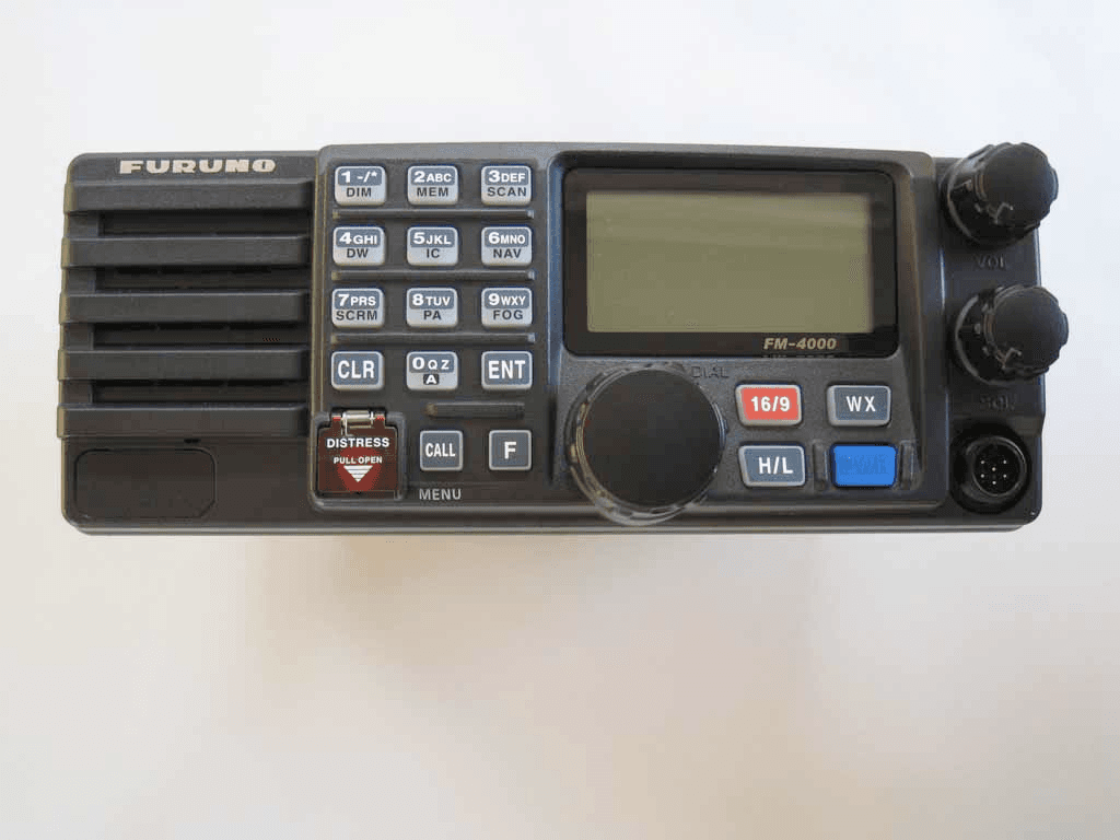
Click to zoom
Application Details
- Equipment Class
- GVH - Part 80 VHF Transmitter (GMDSS)
- Date of Grant
- Dec 21, 2009
- Application Purpose
- Original Equipment
- Date of Application
- Nov 04, 2009
- Equipment Note
- VHF Radiotelephone
- Frequency Range
- 156.03000000 - 157.43000000
- Company
- Furuno USA Inc
- Country
- United States
Documents & Files
Document Text
Text extracted from the exhibit documents filed with the FCC. Open a document above to read the original.
Users Manual
Page 1FM-4000 MARINE VHF RADIOTELEPHONE With Class D DSC Modem and CH70 with receiver FM-4000 Owner’s Manual l l l l l l l l l l l l l l l ** When attached to GPS Receiver Commercial grade ITU class D DSC transceiver Superior receiver performance (80 dB rejection) 30W LoudHailer complete with listen-back and four fog horns, bells, and whistle 2.2-inch internal speaker produces clear, loud audio 2.58" x 1.28" dot matrix display Alphanumeric keypad allows direct entry of channel numbers or selection of most used functions NAV mode displays latitude/longitude, position, time, SOG, COG* Oversized rotary selector, volume and squelch knobs Programmable scan, selectable priority scan, and dual watch One-button access to CH16 and CH9 Treble and bass audio tone control Two inputs for optional Remote MIC Optional voice scrambler Multi-station intercom High and low voltage warnings FM-4000Page 2 1GENERAL INFORMATION ...................................................................................................................... 4 1.1INTRODUCTION .......................................................................................................................... 4 2PACKING LIST ......................................................................................................................................... 5 3OPTIONS ................................................................................................................................................... 5 4.SAFETY/WARNING INFORMATION....................................................................................................... 5 5FCC RADIO LICENSE INFORMATION ................................................................................................. 6 5.1STATION LICENSE ..................................................................................................................... 6 5.2RADIO CALL SIGN ..................................................................................................................... 6 5.3CANADIAN SHIP STATION LICENSING .................................................................................... 6 5.4FCC / INDUSTRY CANADA INFORMATION ............................................................................. 6 6FCC NOTICE ............................................................................................................................................ 7 7GETTING STARTED................................................................................................................................ 8 7.1ABOUT VHF RADIO ................................................................................................................... 8 7.2SELECTING AN ANTENNA .......................................................................................................8 7.3COAXIAL CABLE ........................................................................................................................ 8 8INSTALLATION ......................................................................................................................................... 9 8.1LOCATION ................................................................................................................................... 9 8.2OPTIONAL MMB-84 FLUSH MOUNT INSTALLATION ............................................................ 9 8.3OPTIONAL CMP30 REMOTE MIC........................................................................................... 10 8.4ELECTRICAL CONNECTIONS ................................................................................................. 12 8.5ACCESSORY CABLE ............................................................................................................... 13 8.6CHANGING THE TIME INDICATION ...................................................................................... 14 8.7CHANGING THE COG INDICATION ...................................................................................... 14 9CONTROLS AND INDICATORS ........................................................................................................... 16 9.1CONTROLS AND CONNECTIONS .......................................................................................... 16 10 BASIC OPERATION............................................................................................................................... 22 10.1PROHIBITED COMMUNICATIONS .......................................................................................... 22 10.2RECEPTION ............................................................................................................................... 22 10.3TRANSMISSION ........................................................................................................................ 23 10.4TRANSMIT TIME-OUT TIMER (TOT) ...................................................................................... 23 10.5SIMPLEX/DUPLEX CHANNEL USE ........................................................................................ 23 10.6USA, CANADA, AND INTERNATIONAL MODE ...................................................................... 23 10.7NOAA WEATHER CHANNELS ................................................................................................ 24 10.7.1NOAA Weather Alert................................................................................................. 24 10.7.2NOAA Weather Alert Testing................................................................................... 24 10.8EMERGENCY (CH16 USE) ......................................................................................................25 10.9CALLING ANOTHER VESSEL (CH 16 OR CH9) ................................................................... 25 10.10MAKING TELEPHONE CALLS ................................................................................................ 26 10.11OPERATING ON CHANNELS 13 AND 67 ..........................…
Text truncated - open the document above for the full version.
Users Manual
FM-4000Page 44 11.5.5 Receiving an Individual Call When receiving an Individual call, an acknowledgment must be sent back to the calling station, automatically or manual. The default setting is Automatic, but the radio has a selection that allows you to manually send a reply before the radio will switch to the requested calling channel. The default reply method is Auto- matic, but manual reply (before the radio switches to the requested calling chan- nel) also is available. This selection is useful if you want to see who is calling and requesting you to switch to a channel for communications, similar to the caller ID on a cellular phone. 1. When an Individual call is received, the Individual call ringing alarm sounds. The radio automatically (automatic mode selected) switches to the requested channel and the LCD shows the MMSI of the vessel calling. 2. Press any key to stop the alarm. 3. Press the PTT on the microphone and talk to the calling ship. 11.6 CALL WAITING DIRECTORY The FM-4000 logs received Distress calls and Individual calls. The DSC Call Waiting feature is similar to an an- swering machine where calls are recorded for review. When a call is logged while the radio is set on the DSC Standby function, a “ ” icon appears on the LCD. The FM-4000 can memo- rize up to 30 Distress calls, and up to 80 Individual calls. 11.6.1 Enabling the Call Waiting Feature Follow the steps below to enable or disable the Call Waiting feature. 1. Press and hold down the [ CALL ( MENU )] key until “ Radio SetupRadio Setup Radio SetupRadio Setup Radio Setup” menu appears. 2. Turn the CHANNEL selector knob to select “ DSC SetupDSC Setup DSC SetupDSC Setup DSC Setup” menu. 3. Press the [ ENT ] key, then use the CHANNEL selector knob to select “ Individual AckIndividual Ack Individual AckIndividual Ack Individual Ack.” 4. Press the [ ENT ] key. 5. Turn the CHANNEL selector knob to select “ Able to complyAble to comply Able to complyAble to comply Able to comply” or “ UnableUnable UnableUnable Unable.” 6. Press the [ ENT ] key to store the selected setting. 7. Press the [ CLR ] key twice to return to the “ Radio SetupRadio Setup Radio SetupRadio Setup Radio Setup” menu, then press the [ CLR ] key again to return to radio operation. Page 45FM-4000 11.6.2 Reviewing Received Calls Logged into the Call Waiting Directory 1. Press the [ CALL ( MENU )] key to show the “ DSCDSC DSCDSC DSC Call MenuCall Menu Call MenuCall Menu Call Menu.” 2. Turn the CHANNEL selector knob to select the “ DSC LogDSC Log DSC LogDSC Log DSC Log” menu. 3. Press the [ ENT ] key, then turn the CHANNEL se- lector knob to select the category (“ DistressDistress DistressDistress Distress Alert LOGAlert LOG Alert LOGAlert LOG Alert LOG” or “ DSC Call LogDSC Call Log DSC Call LogDSC Call Log DSC Call Log”) you want to review and/or call back. 4. Press the [ ENT ] key, then turn the CHANNEL selector knob to select the station (name or MMSI number) you want to review and/or call back. 5. Press the [ ENT ] key to review details for the selected station. 6. Press the [ ENT ] key again to call the selected station. NOTE When there is an unread received call, the category (“ Distress Alert LOGDistress Alert LOG Distress Alert LOGDistress Alert LOG Distress Alert LOG” or “ DSC Call LogDSC Call Log DSC Call LogDSC Call Log DSC Call Log”) indication will blink. 11.6.3 To Delete the Received Log from the “DSC Log” Directory 1. Press the [ CALL ( MENU )] key to show the “ DSCDSC DSCDSC DSC Call MenuCall Menu Call MenuCall Menu Call Menu.” 2. Turn the CHANNEL selector knob to select the “ DSC LogDSC Log DSC LogDSC Log DSC Log” menu. 3. Press the [ ENT ] key, then turn the CHANNEL se- lector knob to select “ Log DeleteLog Delete Log DeleteLog Delete Log Delete.” 4. Press the [ ENT ] key, then turn the CHANNEL selector knob to select the category (“ DistressDistress DistressDistress Distress Alert LOGAlert LOG Alert LOGAlert LOG Alert LOG” or “ DSC Call LOGDSC Call LOG DSC Call LOGDSC Call LOG DSC Call LOG”) to delete. 5. Press the [ ENT ] key, then turn the CHANNEL selector knob to select the station (name or MMSI number) to delete. 6. Press and hold the [ ENT ] key until the station (name or MMSI number) is removed from the display. 7. To exit this menu and return to radio operation mode, press the [ 16/9 ] key. FM-4000Page 46 11.7 GROUP CALL This feature allows the user to contact a group of specific vessels (example members of a yacht club) that have DSC radios with Group call function to automatically switch to a desired channel for voice communications. 11.7.1 Setting up a Group Call For this function to operate, the same Group MMSI must be programmed into all the DSC VHF radios within the group of vessels that use this feature. To understand about Group MMSI programming, first a Ship MMSI has to be understood. Ship MMSI: The first three digits called a MID (Mobile Identity Group) of a Ship MMSI denote the country the ship registered for a MMSI. The last six digits are specific to the Ships ID. Ship MMSI Example: If your MMSI is “366123456”, for example, “366” is the MID, which denotes the country, and “123456” is the ID of your ship. Group MMSI: Group MMSI numbers are not assigned by the FCC or other organizations licensed to assign Ship MMSI numbers. The first digit of a Group MMSI is always set to “0” in accordance with international regulations. All FURUNO radios are preset so when program- ming a Group MMSI the first digit is set to “0”. The USCG recommends programming the MID of a Ship MMSI into the second, third and fourth digits of the Group MMSI as it denotes the area the ship is located. The last five digits are decided upon by persons in the Group. This is an important step as all radios in the group must contain the same Group MMSI so they can be contacted by each other. There is a chance that another group of vessels have the same Group MMSI as yours. If this happens, simply change one or more of the last five digits of the Group MM…
Text truncated - open the document above for the full version.
Attestation Statements
Federal Communications Commission Office of Engineering and Technology 445 12th Street, SW Washington, DC 20554 Request for Confidentiality Dear Sir or Madam, In regard to the FCC application for ID ADB9ZWFM4000. The following documents are company confidential, containing technical information of a proprietary nature. Schematic Diagrams Parts list/Tune up info Operational description I respectfully request that documents of these categories be kept confidential. Thank you for you assistance. Best regards, Shane Ryan Type Acceptance Commercial Service FURUNO USA Inc. (360) 834-9300 X5060 (360) 834- 833-5195 [email protected]
External Photos
Bottom
ID Label/Location Info
Bottom
Internal Photos
FCC ID: ADB9ZWFM4000 IC: 1281B-FM4000 FURUNO ELECTRIC CO.,LTD. Top of EUT without case Bottom of EUT without case FCC ID: ADB9ZWFM4000 IC: 1281B-FM4000 FURUNO ELECTRIC CO.,LTD. Side-A of MAIN-UNIT with shield cases Side-A of MAIN-UNIT without shield cases FCC ID: ADB9ZWFM4000 IC: 1281B-FM4000 FURUNO ELECTRIC CO.,LTD. Side-B of MAIN-UNIT Side-A of SUB-UNIT with shield cases FCC ID: ADB9ZWFM4000 IC: 1281B-FM4000 FURUNO ELECTRIC CO.,LTD. Side-A of SUB-UNIT without shield cases Side-B of SUB-unit FCC ID: ADB9ZWFM4000 IC: 1281B-FM4000 FURUNO ELECTRIC CO.,LTD. Side-A of CNTL-2-UNIT with LCD Side-A of CNTL-2-UNIT without LCD FCC ID: ADB9ZWFM4000 IC: 1281B-FM4000 FURUNO ELECTRIC CO.,LTD. Side-B of CNTL-2-UNIT Front of LCD FCC ID: ADB9ZWFM4000 IC: 1281B-FM4000 FURUNO ELECTRIC CO.,LTD. Rear of LCD Side-A of –CONNECTOR-UNIT FCC ID: ADB9ZWFM4000 IC: 1281B-FM4000 FURUNO ELECTRIC CO.,LTD. Side-B of CONNECTOR-UNIT Side-A of TERMINAL-UNIT FCC ID: ADB9ZWFM4000 IC: 1281B-FM4000 FURUNO ELECTRIC CO.,LTD. Side-B of TERMINAL-UNIT Top of chassis FCC ID: ADB9ZWFM4000 IC: 1281B-FM4000 FURUNO ELECTRIC CO.,LTD. Bottom of chassis Inside of panel FCC ID: ADB9ZWFM4000 IC: 1281B-FM4000 FURUNO ELECTRIC CO.,LTD. Inside of microphone (1) Inside of microphone (2)
RF Exposure Info
3/5/2007 Page 1 of 3 FCC ID: K6630283X3S FCC RF Exposure Requirements General information : FCC ID: K6630283X3S Device category: Mobile per Part 2.1091 Environment: Uncontrolled Exposure Mobile devices that operate under Part 80 of this chapter are subject to routine environmental evaluation for RF exposure prior to equipment authorization or use if they operate at frequencies of 1.5 GHz or below and their effective radiated power (ERP) is 1.5 watts or more. However, compliance with the power density limits of 1.1310 is not required. Antenna: The manufacturer does specify an antenna with a gain of 3 dBi to be used with this device. This device has provisions for operation in a vehicle, or a fixed location. Configuration Antenna p/n Type Max. Gain (dBi) Boat Any omni 3 Operating configuration and exposure conditions: The conducted output power is 25 Watts. Typical use qualifies for a maximum duty cycle factor of 50%. The manufacturer also markets this device only for occupation use. - Part 2.1091 states that devices are excluded from routine evaluation if the EIRP is less than 2.46Watt (or 1.5WERP). - Vehicle Operation: The maximum antenna gain that can be used is 3dBi. A coaxial cable of the type RG 58 has a loss of 1dB for a length of 15 feet. MPE Calculation: The minimum separation distance is calculated as follows: The limit for occupation/controlled exposure environment below 300 MHz is .2 mW/cm 2 . 3/5/2007 Page 2 of 3 FCC ID: K6630283X3S Channel frequency: 156.025-157.425 MHz The conducted power output is 25 watt. The coax loss was taken as 1 dB. Antenna gain was taken as 3 dBi 50% talk time in 30 minutes S f 1500 := power density limit for controlled exposure G1dBd2.15+:= gain in dBi G13=dBi S0.2= CL1:= dB coax loss GG1CL−:= gain numeric Gn10 G 10 := Gn1.585=dB R Po Gn⋅() 4π⋅S⋅ () := inches R 2.54 := R88.784= distance in centimeters required for compliance inches34.954= W25:= power in Watts D1:= Duty Factor in decimal % (1=100%) 1 for FM E15:= exposure time in minutes U30:= (use 6 for controlled and 30 for uncontrolled ) WexpW D⋅ E U ⎛ ⎜ ⎝ ⎞ ⎠ ⋅:= PC E U ⎛ ⎜ ⎝ ⎞ ⎠ 100⋅:= Wexp12.5=WattsPC50= % on time Po12500:=mWatts f300:= Frequency in MHz dBd.85:= antenna gain in dBd 3/5/2007 Page 3 of 3 FCC ID: K6630283X3S Conclusion: The device complies with the MPE requirements by providing a safe separation distance of 0.89m between the antenna, including any radiating structure, and any persons when normally operated . Proposed RF exposure safety information to include in User’s Manual : “FCC RF Exposure Requirements: CAUTION: The antenna(s) used for this transmitter must not be co-located or operating in conjunction with any other antenna or transmitter. This device is approved with emissions having a source-based time- averaging duty factor not exceeding 50%. Failure to observe these restrictions will result in exceeding the FCC RF exposure limits.
Test Report
Page 1 of 35 REPORT ON Radio testing of the FURUNO FM-4000 In accordance with ANSI/TIA/EIA-603, RSS-182 October 2009Report number TA2009-001 FURUNO ELECTRIC CO.,LTD. FM-4000 Channel Settings HILOW 1CH16156.800156.80025k25W1W 2CH70156.525156.52525k25W1W 3 4 5 6 7 8 9 10 11 12 13 14 15 16 17 18 19 20 Report number TA2009-001Page 3 of 35 Power Transmit Frequency [MHz] CH No. Receive Frequency [MHz] CH Spacing Shown on LCD FURUNO ELECTRIC CO., LTD. NAME OF TEST:R.F. Power Output (Conducted) SPECIFICATION: 47 CFR 2.1046 (a) GUIDE: ANSI/TIA/EIA-603, Paragraph 2.2.1 TEST EQUIPMENT: As per attached page The EUT was connected to a resistive coaxial attenuator of normal load impedance, and the modulated output powerwas measured by means of an R.F. power meter. Measurement accuracy is ± 4% MEASUREMENT PROCEDURE 24.000 NOMINAL, MHz 70 0.803 0.880 1. 2. MEASUREMENT RESULTS 156.800 CHANNEL R.F. POWER, WATTS 16 HIGH Report number TA2009-001Page 4 of 35 24.010 156.525 LOW FURUNO ELECTRIC CO., LTD. (1) COAXUAL ATTENUATORWEINSCHELL 49-10-43KL458 (2) RF COUPLERADVANTEST TR415339730008 2349A02533 (2) Agilent 8901B POWER MODE3026A02806 (4) POWER METER (3) POWER SENSORAgilent 8482B Serial NumberInstruments Test Sample (5) FREQUENCY COUNTERAgilent 8901B FREQUENCY MODE3026A02806 TRANSMITTER POWER CONDUCTED MEASUREMENTS Power Supply TEST 1: R.F. POWER OUTPUT TEST 2: FREQUENCY STABILITY (4)(3)(1) Description (5) Report number TA2009-001Page 5 of 35 FURUNO ELECTRIC CO., LTD. NAME OF TEST:Unwanted Emissions (Conducted) SPECIFICATION: 47 CFR 2.1051 GUIDE: ANSI/TIA/EIA-603, Paragraph 2.2.13 TEST EQUIPMENT: As per attached page The emissions were measured for the worst case as follows: (a): within a band of frequencies defined by the carrier frequency plus and minus one channel. (b): from the lowest frequency generated in the EUT and to at least the 10th harmonic of the carrier frequency, or 40GHz, whichever is lower. The magnitude of spurious emissions that are attenuated more than 20dB below the permissible value need not be specified. MEASUREMENT RESULTS: FREQUENCY OF CARRIER, MHz=,, SPECTRUM SEARCHED, GHz=0 to 10 x Fc MAXIMUM RESPONSE, Hz= ALL OTHER EMISSIONS=>= 20dB BELOW LIMIT MEASUREMENT PROCEDURE 3. 1. 2. 156.8156.525 2900 0 Report number TA2009-001Page 6 of 35 FURUNO ELECTRIC CO., LTD. (1) (3) SPECTRUM ANALYZER (2) COAXUAL ATTENUATOR Instruments KL458 (2) COAXUAL ATTENUATORAgilent 8498A1801A02723 (1) AUDIO GENERATORAgilent 8903B2742A03633 (2)(3) DescriptionSerial Number Test Sample Power Supply ADVANTEST TR417385580005 WEINSCHELL 49-10-43 TEST 1: OCCUPIED BANDWIDTH (IN-BAND SPURIOUS) TEST 2: OUT-OF-BAND SPURIOUS Report number TA2009-001Page 7 of 35 TRANSMITTER SPURIOUS EMISSION FURUNO ELECTRIC CO., LTD. NAME OF TEST:Unwanted Emissions (Conducted) LIMIT'S), dBc:-(43+10xLOG(P))=(Watts) -(43+10xLOG(P))=(Watts) High Power -13.0-84.927.9 -13.0-85.128.1 MARGIN, dBmdBcdB 156.8000 156.5250 FREQUENCYFREQUENCY EMISSION, MHz 313.6000 313.0500 TUNED, MHz -5725 Report number TA2009-001Page 8 of 35 -43 LEVEL,LEVEL, 1 FURUNO ELECTRIC CO., LTD. NAME OF TEST:Unwanted Emissions (Conducted) LIMIT'S), dBc:-(43+10xLOG(P))=(Watts) -(43+10xLOG(P))=(Watts) Low Power dBc LEVEL,MARGIN, 1 -71.228.2 dB -70.927.9 25 156.8000313.6000-13.0 313.0500-13.0 LEVEL, TUNED, MHzEMISSION, MHzdBm FREQUENCY -57 FREQUENCY 156.5250 -43 Report number TA2009-001Page 9 of 35 FURUNO ELECTRIC CO., LTD. NAME OF TEST:Field Strength of Spurious Radiation SPECIFICATION: 47 CFR 2.1053 (a) GUIDE: ANSI/TIA/EIA-603, Paragraph 1.2.12 Definition: Radiated spurious emissions are emissions from the equipment when transmitting load on a frequency or frequencies which are outside an occupied band sufficient to ensure transmission of information of required quality for the class of communications desired. Method of measurement Connect the equipment as illustrated. Adjust the spectrum analyzer for the following settings: 1)Resolution Bandwidth <= 3kHz 2)Video Bandwidth >= 10kHz 3)Sweep Speed <= 2000Hz/second 4)Detector Mode = Positive Peak Place the transmitter to be tested on the turntable in the standard test site. The transmitter is transmitting into a non-radiating load which is placed on the turntable. The RF cable to this load should be of minimum length. STANDARD TEST SITE For each spurious measurment the test antenna should be adjusted to the correct length for the frequency involved. This length maybe determined from a calibration ruler supplied with the equipment. Measurements shall be made from the lowest radio frequency generated in the equipment to the tenth harmonic of the carrier, except for the region close to the carrier qeual to ± the test bandwidth (see section 1.3.4.4). For each spurious frequency, raise and lower the test antenna from 1 m to 4 m to obtain a maximum reading on the spectrum analyzer with the test antenna at horizontal polarity. MEASUREMENT PROCEDURE 1.2.12.1 Test antenna B) 1.2.12.2 A) SPECTRUM ANALYZER D) E) TRANSMITTER UNDER TEST STANDARD TRANSMITTER LOAD Report number TA2009-001Page 10 of 35 C) FURUNO ELECTRIC CO., LTD. NAME OF TEST:Field Strength of Spurious Radiation Repeat step E) for each spurious frequency with the test antenna polarized vertically. STANDARD TEST SITE Reconnect the equipment as illustrated. Keep the spectrum analyzer adjusted as in step B). Remove the transmitter and replace it with a substitution antenna (the antenna should be half-wavelength for each frequency involved). The center of the substitutuion antenna should be approximately at the same location as the center of the transmitter. At lower frequencies, where the substitution antenna is very long, this will be impossible to achieve when the antenna is plarized vertically. In such case the lower end of the antenna should be 0.3m above the ground. Feed the substitution antenna at the transmitter end with a signal generator connected to the antenna by means of a non-radiating cable. With the antennas at both ends horizontally polarized and with the signal ge…
Text truncated - open the document above for the full version.
Contact Information
Applicant
Bill Haynes(Deep Sea Product Manager)
Technical Contact
FURUNO USAShane Ryan
[email protected]360 834-9300
4400 NW PACIFIC RIM BLVD · CAMAS, Washington · United States
Technical Specifications
| # | Rule Parts | Frequency Range | Power Output | Emission | Tolerance |
|---|---|---|---|---|---|
| 4 | 80.1101(c)(4) | 156.03 MHz - 157.43 MHz | 1 W | 16K0G2B | 8 ppm |
Other Applications from Furuno USA Inc
ADB-9ZWRTR137
Feb 18, 2026Transceiver unit for the radar sensor
Equipment Class
MRD - Marine RadarADB9ZWRTR136
Jul 01, 2024Transceiver unit for the radar sensor
Equipment Class
MRD - Marine Radar
ADB9ZWRTR128
Apr 06, 2022Transceiver unit for the radar sensor
Equipment Class
MRD - Marine Radar
ADB9ZWRTR133
Sep 26, 2021Transceiver unit for the radar sensor
Equipment Class
MRD - Marine Radar
ADB9ZWRTR129
May 23, 2021Transceiver unit for the radar sensor
Equipment Class
MRD - Marine Radar