ADB9ZWFM8900SGMDSS VHF
Furuno USA Inc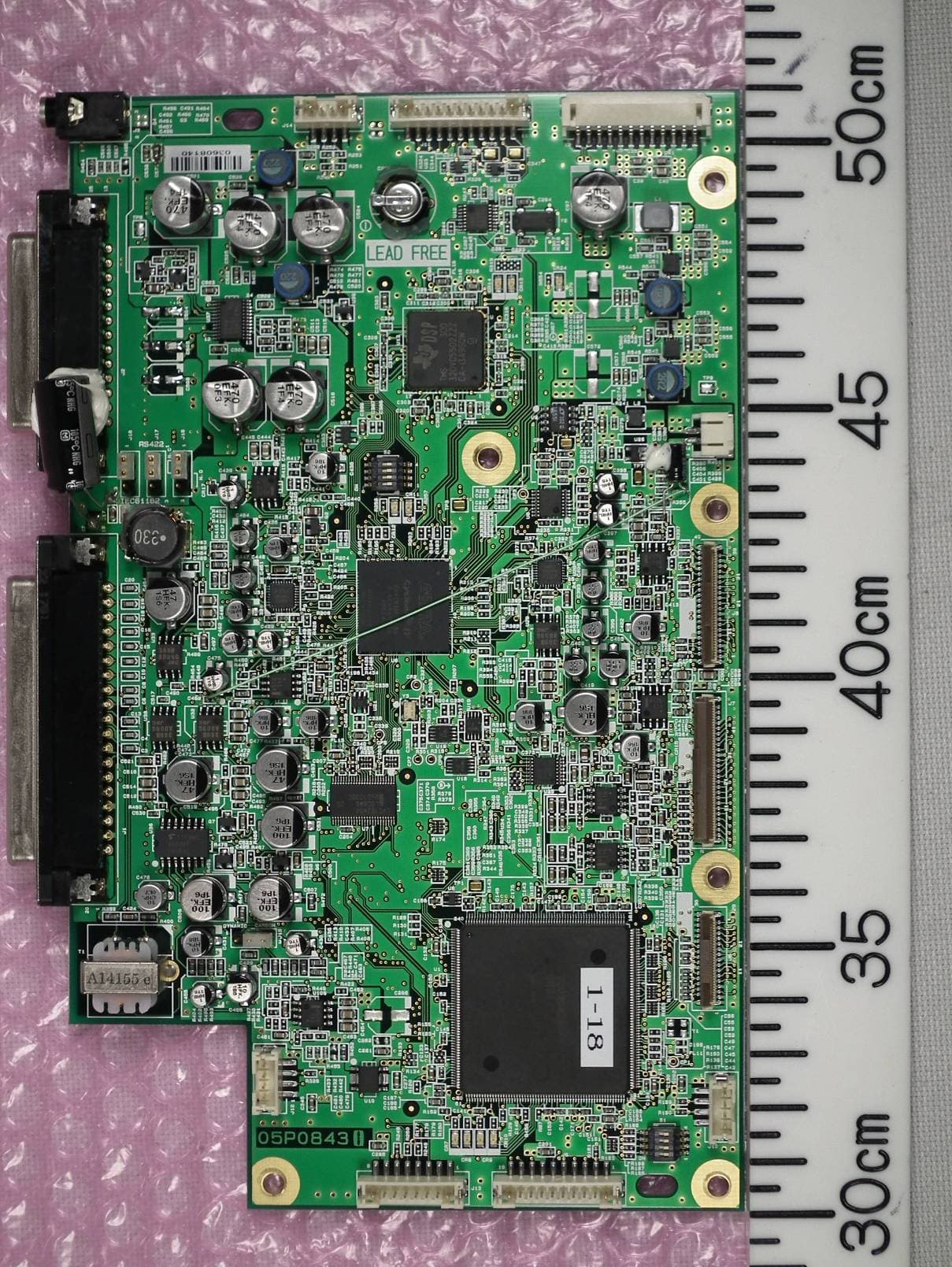
Click to zoom
Application Details
- Equipment Class
- GVH - Part 80 VHF Transmitter (GMDSS)
- Date of Grant
- Oct 24, 2012
- Application Purpose
- Original Equipment
- Date of Application
- Aug 28, 2012
- Equipment Note
- GMDSS VHF
- Frequency Range
- 155.00000000 - 161.47500000
- Company
- Furuno USA Inc
- Country
- United States
Documents & Files
Document Text
Text extracted from the exhibit documents filed with the FCC. Open a document above to read the original.
Users Manual
VHF RADIOTELEPHONE FM-8900S OPERATOR'S MANUAL www.furuno.com MODEL The paper used in this manual is elemental chlorine free. ・FURUNO Authorized Distributor/Dealer 9-52 Ashihara-cho, Nishinomiya, 662-8580, JAPAN A:APR2012 . Printed in Japan All rights reserved. Pub. No.OME-56800-A *00017619910**00017619910* (YOTA)FM-8900S *00017619910**00017619910* * 0 0 0 1 7 6 1 9 9 1 0 * i IMPORTANT NOTICES General • This manual has been authored with simplified grammar, to meet the needs of international us- ers. • The operator of this equipment must read and follow the descriptions in this manual. Wrong op- eration or maintenance can cancel the warranty or cause injury. • Do not copy any part of this manual without written permission from FURUNO. • If this manual is lost or worn, contact your dealer about replacement. • The contents of this manual and equipment specifications can change without notice. • The example screens (or illustrations) shown in this manual can be different from the screens you see on your display. The screens you see depend on your system configuration and equip- ment settings. • Save this manual for future reference. • Any modification of the equipment (including software) by persons not authorized by FURUNO will cancel the warranty. • All brand and product names are trademarks, registered trademarks or service marks of their respective holders. How to discard this product Discard this product according to local regulations for the disposal of industrial waste. For disposal in the USA, see the homepage of the Electronics Industries Alliance (http://www.eiae.org/) for the correct method of disposal. How to discard a used battery Some FURUNO products have a battery(ies). To see if your product has a battery, see the chapter on Maintenance. Follow the instructions below if a battery is used. Tape the + and - terminals of battery before disposal to prevent fire, heat generation caused by short circuit. In the European Union The crossed-out trash can symbol indicates that all types of batteries must not be discarded in standard trash, or at a trash site. Take the used batteries to a battery collection site according to your national legislation and the Batteries Directive 2006/66/EU. In the USA The Mobius loop symbol (three chasing arrows) indicates that Ni-Cd and lead-acid rechargeable batteries must be recycled. Take the used batteries to a battery collection site according to local laws. In the other countries There are no international standards for the battery recycle symbol. The number of symbols can increase when the other countries make their own recycle symbols in the future. Cd Ni-CdPb ii SAFETY INSTRUCTIONS Indicates a condition that can cause death or serious injury if not avoided. Indicates a condition that can cause minor or moderate injury if not avoided. The user must read the appropriate safety instructions before attempting to install or operate the equipment. WARNING CAUTION Warning, CautionProhibitive ActionMandatory Action WARNING WARNING Do not open the equipment. Hazardous voltage which can cause electrical shock, burn or serious injury exists inside the equipment. Only qualified personnel should work inside the equipment. Immediately turn off the power at the switchboard if water leaks into the equipment or the equipment is emitting smoke or fire. Continued use of the equipment can cause fire or electrical shock. Contact a FURUNO agent for service. Do not disassemble or modify the equipment. Fire, electrical shock or serious injury can result. Do not place liquid-filled containers on the top of the equipment. Fire or electrical shock can result if a liquid spills into the equipment. Do not operate the equipment with wet hands. Electrical shock can result. Turn off the power immediately if you feel the equipment is behaving abnormally. Turn off the power at the switchboard if the equipment becomes abnormally warm or is emitting odd noises. Contact a FURUNO dealer or agent for advice. Make sure no rain or water splash leaks into the equipment. Fire or electrical shock can result if water leaks in the equipment. Use the proper fuse. Use of the wrong fuse can cause fire or electrical shock. Do not approach the antenna closer than listed below when it is transmitting. The antenna emits radio waves that can be harmful to the human body. RF power density on antenna aperture Distance Description required by 100 W/m 2 10 W/m 2 2 W/m 2 IEC 60945 IEC 60945 MPE by FCC (MPE: Minimum Permissible Exposure) Any repair work must be done by a licensed radio technician. Improper repair work can cause fire or electrical shock. Do not operate the [DISTRESS] key except in case of a life-endangering situation on your vessel. Operating the [DISTRESS] key transmits the distress alert. Accidental transmission may prevent search and rescue operations for actual emergency. If the distress alert is accidentally transmitted, contact the nearest station to cancel the alert. 0.89 m 0.39 m 0.12 m SAFETY INSTRUCTIONS iii The TFT LCD is constructed using the latest LCD techniques, and displays 99.99% of its pixels. The remaining 0.01% of the pixels may drop out or blink, however this is not an indication of malfunction. About the TFT LCD Warning labels are attached to the equipment. Do not remove any label. If a label is missing or damaged, contact a FURUNO agent or dealer about replacement. Name: Warning Label 1 Type: 86-003-1011-3 Code No.: 100-236-233-10 CAUTION WARNING LABELS Do not apply strong pressure to the LCD, which is made of glass. Injury can result if the LCD breaks. Name: Warning Label Type: 14-055-4202-1 Code No.: 100-245-221-10 Name: High Temp Warning Label Type: 05-089-2142-0 Code No.: 100-301-620-00 CAUTION If the distress alert is accidentally transmitted, contact the nearest coast station and inform them of the accidental transmission, providing the following data: a) Ship's name b) Ship's call sign and DSC number c) Position at time of transmission d) Time of transmissio…
Text truncated - open the document above for the full version.
Users Manual
3. DSC DISTRESS OPERATIONS 3-13 3.4How to Receive a Distress Relay There are three types of distress relay messages: distress relay for all ships, distress relay area and distress relay from coast station. When you receive a distress relay message, continue monitoring CH16. The audio alarm sounds and the LED flashes in red. The icon () appears in the tab area and the applicable pop-up message ap- pears on the screen. 1. Press the CANCEL key to silence the audio alarm, stop the flashing of the LED and erase the pop-up message. 2. Watch CH16. 3.5How to Cancel the Distress Alert You can cancel the distress alert while it is being sent or while waiting for its acknowl- edgement as follows. 1. Rotate the CHANNEL/ENTER knob to select [CANCEL] in the user options area then push the knob. The following message appears on the screen. Distress relay for all ships Distress relay area Distress relay from coast station 3. DSC DISTRESS OPERATIONS 3-14 2. Rotate the CHANNEL/ENTER knob to select [Yes] then push the knob to cancel the distress alert over CH70. After transmitting the distress cancel call, the follow- ing message appears on the screen. 3. Push the CHANNEL/ENTER knob to erase the message. The following message appears on the screen. 4. Communicate with all ships via radiotelephone referring to the message shown at step 3. 5. Push the CHANNEL/ENTER knob. The following message appears on the screen. 6. With [Finish] selected, push the CHANNEL/ENTER knob. 7. Rotate the CHANNEL/ENTER knob to select [QUIT] in the user options area then push the knob. The RT screen appears. 4-1 4.DSC GENERAL MESSAGE CALLING, RECEIVING General procedure for non-distress DSC messages The procedure for sending and receiving non-distress DSC messages is similar among message types. The following is an example of the sequence for an individual call. 1. Send the individual message. 2. Wait for the individual message acknowledgement. 3. Start the voice communication. 4.1Individual Call The individual call is for calling a specific station. After sending an individual call, called ACK RQ transmission, wait to receive the acknowledge back (ACK BQ) signal from the receiving station. 4.1.1How to send an individual call 1. Press the OTHER DSC MSG key. (1) (2) (3) Your Ship Coast Station (1) DSC Message (Called Acknowledge Request (ACK RQ) Signal) (2) Acknowledge Back (ACK BQ) Signal (3) Voice communication 4. DSC GENERAL MESSAGE CALLING, RECEIVING 4-2 2. Rotate the CHANNEL/ENTER knob to select [MSG TYPE] then push the knob. 3. Rotate the CHANNEL/ENTER knob to select [INDIVIDUAL MSG] then push the knob. 4. With [TO] selected, push the CHANNEL/ENTER knob. 5. Rotate the CHANNEL/ENTER knob to select [DIRECT INPUT], [ADDRESS BOOK DATA] or [AIS TARGET DATA] then push the knob. [DIRECT INPUT]: Enter the MMSI of the station where to send the call then push the CHANNEL/ENTER knob. [ADDRESS BOOK DATA]: Select an MMSI from the [ADDRESS BOOK] (see section 5.13) then push the CHANNEL/ENTER knob. [AIS TARGET DATA]: Select an MMSI from the [AIS TARGET LIST] then push the CHANNEL/ENTER knob. AIS target list If an AIS transponder is connected to the radiotelephone, you can select an MMSI from the [AIS TARGET LIST]. 6. Rotate the CHANNEL/ENTER knob to select [PRIORITY] then push the knob. 7. Rotate the CHANNEL/ENTER knob to select [ROUTINE], [SAFETY] or [URGEN- CY] then push the knob. 8. With [COMM CH] selected, push the CHANNEL/ENTER knob. 9. Rotate the CHANNEL/ENTER knob to select [SELECT] or [MANUAL] then push the knob. [SELECT]: The options window as shown in the right figure appears. Rotate the CHANNEL/ENTER knob to select the channel then push the knob. [MANUAL]: Enter the channel then push the CHANNEL/ENTER knob. 10. With [GO TO CALL] selected, push the CHANNEL/ENTER knob to send the indi- vidual call. The screen changes as shown below. TX 4. DSC GENERAL MESSAGE CALLING, RECEIVING 4-3 The timer starts counting up the time since the call was sent. After the call is sent, the equipment waits for acknowledgement of the call, showing the WAIT FOR ACK screen as below. When the ACK is received, the audio alarm sounds and the pop-up message "ROUTINE (or SAFETY, URGENCY) INDIVIDUAL ACK received! [CANCEL]: Stop alarm" appears on the screen as below. The timer starts counting up the time since the ACK was received. There are three types of ACK messages; [ABLE ACK], [UNABLE ACK] or [ABLE CHANGE CHANNEL ACK]. 11. Do one of the following depending on the message type shown at step 10. Able acknowledge call received 1) Press the CANCEL key to silence the audio alarm and erase the pop-up mes- sage. 2) Communicate by radiotelephone. 3) After you have completed communications, rotate the CHANNEL/ENTER knob to select [QUIT] in the user options area then push the knob. Able to change channel acknowledge call received This call means that the station you sent the individual call to accepts your call with the channel specified. 1) Press the CANCEL key to silence the audio alarm and erase the pop-up mes- sage. The following message appears on the screen. 2) Press the CANCEL key to erase the message. The working channel is changed to one that the station specified. You can now communicate by ra- diotelephone. 3) After you have completed communications, rotate the CHANNEL/ENTER knob to select [QUIT] in the user options area then push the knob. REGIST 4. DSC GENERAL MESSAGE CALLING, RECEIVING 4-4 Unable acknowledge call received 1) Press the CANCEL key to silence the audio alarm and erase the pop-up mes- sage. The reason for [UNABLE ACK] is displayed on the screen. Reason for unable to acknowledge 2) Rotate the CHANNEL/ENTER knob to select [QUIT] in the user options area then push the knob. Note: If the coast station sends the message "QUEUE INDICATION", wait un- til your turn comes. If there is no response from the station, do one of the following procedures: • Resend call: Rotate the CHANNEL/ENTER knob to select [RESEND] in the user options area then push th…
Text truncated - open the document above for the full version.
Users Manual
5. MENU OPERATION 5-21 Rotate the CHANNEL/ENTER knob to select [AUDIO] on the [MENU] screen then push the knob. 5.20Alarm Lists The [ALARM] menu shows all currently violated alarms. When an error occurs, a pop- up message and a flashing error icon appear on the screen. Press the CANCEL key to close the pop-up message and stop the flashing of the error icon. When the error is removed, the error icon disappears. Rotate the CHANNEL/ENTER knob to select [ALARM] on the [MENU] screen then push the knob. The following screen appears. There are three kinds of errors: [TX PLL UNLOCK], [RX PLL UNLOCK], [DSC PLL UNLOCK]. Errors are displayed in the order shown above, not in the order of occurrence. An error is deleted from the list when the cause for the error is removed. These alarms are listed when the following messages appear. Default: [2] Turn beep on (setting: [1] - [3]) or off (setting: [0]) when a key is pressed. Default: [MUTE] Turn the speaker on or off when the handset is off hook. Rotate the CHANNEL/ENTER knob to set volume then push the knob. Default: [OFF] Adjust tone quality for speaker. Turn the speakers except in-use one on or off. [PUBLIC]: On, [PRIVATE]: Off Error icon 5. MENU OPERATION 5-22 This page is intentionally left blank. 6-1 6.REMOTE HANDSET 6.1Controls Remote station RB-8900(-W) (option) Description of controls for remote station (handset) ControlFunction DW keyTurns the DW function on or off (see section 1.9). HI/LO keyChanges the output power to high (25 W) or low (1 W). CH16 keySwitches to the RT (radiotelephone) screen and sets CH16. SCAN keyTurns the scan function on or off (see section 1.10). S, T keys• Selects the menu items. • Selects the channel on the RT screen. • Adjusts the setting values. SQ keyAdjusts the squelch. Press the SQ key on the RT/OCCUPIED screen then press the S or T key within three seconds to adjust the squelch (setting range: AUTO, 0 to 10). To get auto squelch adjustment, press the T key with the setting 0 (indication: SQA). VOL keyAdjusts the volume. Press the VOL key on the RT/OCCUPIED screen then press the S or T key within three seconds to adjust the volume (setting range: 0 to 10). ENTER key• Moves down one layer when you save the menu option in a layer other than the lowest one. In the undermost layer, opens the setting window. • Confirms a selection. CANCEL key• Silences the audio alarm. • Returns one layer in a multi-layer menu. In the top layer, closes the menu then displays the RT screen. • Cancels the setting in the setting window then goes back one layer in the menu. • Cancels the intercom call. key Turns the loudspeaker on or off. HS-8900(-W) Remote handset LCD Keyboard HG-8900(-W) Handset hanger 6. REMOTE HANDSET 6-2 6.2How to Turn On/Off the Power A handset does not have a power key. Turn on or off the power from the transceiver unit. 6.3Radiotelephone (RT) Screen Below are the radiotelephone (RT) screens on the remote handset. MENU keyOpens/closes the menu. 0 to 9 keys• Enters the channel on the RT screen. • Selects the menu items. CONTRAST keyShort press: Opens the contrast setup screen. Press the S or T key to adjust the contrast. Long press (more than three seconds): Restores the contrast to the de- fault setting. BRILL keyOpens the brill setup screen. Press the S or T key to adjust the brill. You can also use the BRILL key. No.Meaning 1RX signal strength (This icon does not appear while transmitting.) 2Output power ([HI]: High, [LO]: Low) 3Channel type ([SIMP]: Simplex, [DUP]: Duplex) 4Spinner rotates when the equipment is functioning normally. 5Channel region ([INT’L], [USA], [CANADA], [INLAND-W], [PRIVATE]) 6Channel 7 Loudspeaker on () or off () 8Volume for loudspeaker (0 to 10) 9Squelch level (0 to 10, AUTO (Indication is [SQA].)) 10Terminal ID ([L]: Left wing handset, [R]: Right wing handset, [1] to [4]: Remote handset 1 to 4) ControlFunction 2 1 3 4 5 9 10 6 7 8 DW screen Common RT screen Scan screen When no terminal has operation right and a remote handset is off hook, the following screen appears. A remote handset can get the operation right if you hook on then hook off. 6. REMOTE HANDSET 6-3 6.4How to Adjust the Brilliance and Contrast You can adjust the brilliance of the display and the panel for each remote handset sep- arately. Also, you can adjust the contrast for each remote handset. Brilliance 1. Press the BRILL key to show the [BRILL] setting window. 2. Press the S or T key to adjust the brilliance. 3. Press the ENTER key to save the settings and close the window. To cancel the settings, press the CANCEL key in- stead of the ENTER key to close the window. Note: The [BRILL] setting window automatically closes when there is no menu oper- ation for three seconds. Contrast 1. Press the CONTRAST key to show the [CONTRAST] set- ting window. 2. Press the S or T key to adjust the contrast. 3. Press the ENTER key to save the settings and close the window. To cancel the settings, press the CANCEL key in- stead of the ENTER key to close the window. Note: The [CONTRAST] setting window automatically closes when there is no menu operation for three seconds. 6.5How to Select the Channel Region, Channel Channel region 1. Press the MENU key to open the [MENU] screen. 2. Press the S or T key to select [REGION] then press the ENTER key. 3. Press the S or T key to select the channel mode desired then press the ENTER key. The following modes are available. • [INT’L]: International mode • [USA] : USA mode • [CANADA]: CANADA mode • [INLAND-W]: Inland waterway mode • [PRIVATE]: Private channel 6. REMOTE HANDSET 6-4 Note 1: Only permitted channel regions are displayed, which are set by the install- er of the equipment. Note 2: Private channels are available only where permitted by the authorities. The [USA], [CANADA], [INLAND-W], [PRIVATE] can also be set by a qualified service technician. Channel The channel can be set manually on the RT screen. Enter the channel by one of the methods below. Enter channel with the S or T key: Pres…
Text truncated - open the document above for the full version.
Cover Letter(s)
Federal Communications Commission Office of Engineering and Technology 445 12th Street, SW Washington, DC 20554 To whom it may concern, We hereby respectfully request that under the provision of FCC rules section0.457(d) and0.459, the following documents submitted in support of this application for ADB9ZWFM8900Scertification be provided with confidential status. Schematics Parts list/Tune up info Operational description These documents contain trade secrets that are treated as confidential by us. Substantial competitive harm to our company business could result should they be made available to the public. Best regards , Shane Ryan Type Acceptance Commercial Service FURUNO USA Inc. (360) 834-9300 X5060 (360) 834- 833 -5195 [email protected]
Cover Letter(s)
Federal Communications Commission Office of Engineering and Technology 445 12th Street, SW Washington, DC 20554 To whom it may concern, We hereby respectfully request that under the provision of FCC rules section0.457(d) and0.459, the following documents submitted in support of this application for ADB9ZWFM8900Scertification be provided with confidential status. Schematics Parts list/Tune up info Operational description These documents contain trade secrets that are treated as confidential by us. Substantial competitive harm to our company business could result should they be made available to the public. Best regards , Shane Ryan Type Acceptance Commercial Service FURUNO USA Inc. (360) 834-9300 X5060 (360) 834- 833 -5195 [email protected]
External Photos
Furuno Labotech International Co., Ltd. Document. number: FLI 01-11-079 Date of issue: 29 Feburuary 2012 - Page 2 of 35 - 1 Transceiver Unit FM-8900S 1.1 Front View (Showing Panel and ID Label (upper left side of the Panel) Furuno Labotech International Co., Ltd. Document. number: FLI 01-11-079 Date of issue: 29 Feburuary 2012 - Page 3 of 35 - 1.2 Front View (showing Front Panel) Furuno Labotech International Co., Ltd. Document. number: FLI 01-11-079 Date of issue: 29 Feburuary 2012 - Page 4 of 35 - 1.3 Rear View Furuno Labotech International Co., Ltd. Document. number: FLI 01-11-079 Date of issue: 29 Feburuary 2012 - Page 5 of 35 - 1.4 ID Label (Name Plate) Furuno Labotech International Co., Ltd. Document. number: FLI 01-11-079 Date of issue: 29 Feburuary 2012 - Page 6 of 35 - 1.5 Inside Top View (with Top Cover removed) Furuno Labotech International Co., Ltd. Document. number: FLI 01-11-079 Date of issue: 29 Feburuary 2012 - Page 7 of 35 - 1.6 Inside Top View (with Shield cover removed, showing TRX_WR Board 05P0841 (upper) and PWR Board 05P0849 (lower)) Furuno Labotech International Co., Ltd. Document. number: FLI 01-11-079 Date of issue: 29 Feburuary 2012 - Page 8 of 35 - 1.7 TRX_WR Board 05P0841 Front side Furuno Labotech International Co., Ltd. Document. number: FLI 01-11-079 Date of issue: 29 Feburuary 2012 - Page 9 of 35 - 1.8 TRX_WR Board 05P0841 Rear side Furuno Labotech International Co., Ltd. Document. number: FLI 01-11-079 Date of issue: 29 Feburuary 2012 - Page 10 of 35 - 1.9 PWR Board 05P0849 Front side Furuno Labotech International Co., Ltd. Document. number: FLI 01-11-079 Date of issue: 29 Feburuary 2012 - Page 11 of 35 - 1.10 PWR Board 05P0849 Rear side Furuno Labotech International Co., Ltd. Document. number: FLI 01-11-079 Date of issue: 29 Feburuary 2012 - Page 12 of 35 - 1.11 Inside Bottom View (showing MAIN Board 05P0843 Front side) Furuno Labotech International Co., Ltd. Document. number: FLI 01-11-079 Date of issue: 29 Feburuary 2012 - Page 13 of 35 - 1.12 MAIN Board 05P0843 Front side Furuno Labotech International Co., Ltd. Document. number: FLI 01-11-079 Date of issue: 29 Feburuary 2012 - Page 14 of 35 - 1.13 MAIN Board 05P0843 Rear side Furuno Labotech International Co., Ltd. Document. number: FLI 01-11-079 Date of issue: 29 Feburuary 2012 - Page 15 of 35 - 1.14 Rear of Front Panel (showing PANEL Board 05P0882 Rear side and Loudspeaker (upper)) Furuno Labotech International Co., Ltd. Document. number: FLI 01-11-079 Date of issue: 29 Feburuary 2012 - Page 16 of 35 - 1.15 PANEL Board 05P0882 Rear side Furuno Labotech International Co., Ltd. Document. number: FLI 01-11-079 Date of issue: 29 Feburuary 2012 - Page 17 of 35 - 1.16 PANEL Board 05P0882 Front side Furuno Labotech International Co., Ltd. Document. number: FLI 01-11-079 Date of issue: 29 Feburuary 2012 - Page 18 of 35 - 1.17 Back of Front Panel (with PANEL Board removed)
External Photos
Furuno Labotech International Co., Ltd. Document. number: FLI 01-11-079 Date of issue: 29 Feburuary 2012 - Page 1 of 35 - Photographs of Furuno VHF Radio Telephone FM-8900S Contents 1 TRANSCEIVER UNIT FM-8900S .............................................................................................................. 2 2 JUNCTION BOX IF-8900 ......................................................................................................................... 19 3 REMOTE HANDSET HS-8900 AND REMOTE HANDSET HANGER HG-8900 .................................... 22 4 WATERTIGHT REMOTE HANDSET HS-8900-W AND WATERTIGHT REMOTE HANDSET HANGER HG-8900-W ................................................................................................................................. 29
ID Label/Location Info
Furuno Labotech International Document number: FLI 01-12-027 Date of issue: 23 May 2012 Form: Q053/01 - Page 1 of 2 - Identification of Equipment for the Furuno VHF RADIOTELEPHONE FM-8900S (FCC Rule, 47 CFR, 2.925) Transceiver Unit FM-8900S, 1 ID Label The following nameplate is permanently fixed on the corresponding equipment unit. FCC ID: ADB9ZWFM8900S Material of Nameplate: Polyester film, 0.2 mm thick Furuno Labotech International Document number: FLI 01-12-027 Date of issue: 23 May 2012 Form: Q053/01 - Page 2 of 2 - 2 ID Label Location ID Label is affixed on the Transceiver unit.
Internal Photos
Furuno Labotech International Co., Ltd. Document. number: FLI 01-11-079 Date of issue: 29 Feburuary 2012 - Page 7 of 35 - 1.6 Inside Top View (with Shield cover removed, showing TRX_WR Board 05P0841 (upper) and PWR Board 05P0849 (lower)) Furuno Labotech International Co., Ltd. Document. number: FLI 01-11-079 Date of issue: 29 Feburuary 2012 - Page 8 of 35 - 1.7 TRX_WR Board 05P0841 Front side Furuno Labotech International Co., Ltd. Document. number: FLI 01-11-079 Date of issue: 29 Feburuary 2012 - Page 9 of 35 - 1.8 TRX_WR Board 05P0841 Rear side Furuno Labotech International Co., Ltd. Document. number: FLI 01-11-079 Date of issue: 29 Feburuary 2012 - Page 10 of 35 - 1.9 PWR Board 05P0849 Front side Furuno Labotech International Co., Ltd. Document. number: FLI 01-11-079 Date of issue: 29 Feburuary 2012 - Page 11 of 35 - 1.10 PWR Board 05P0849 Rear side Furuno Labotech International Co., Ltd. Document. number: FLI 01-11-079 Date of issue: 29 Feburuary 2012 - Page 12 of 35 - 1.11 Inside Bottom View (showing MAIN Board 05P0843 Front side) Furuno Labotech International Co., Ltd. Document. number: FLI 01-11-079 Date of issue: 29 Feburuary 2012 - Page 13 of 35 - 1.12 MAIN Board 05P0843 Front side Furuno Labotech International Co., Ltd. Document. number: FLI 01-11-079 Date of issue: 29 Feburuary 2012 - Page 14 of 35 - 1.13 MAIN Board 05P0843 Rear side Furuno Labotech International Co., Ltd. Document. number: FLI 01-11-079 Date of issue: 29 Feburuary 2012 - Page 15 of 35 - 1.14 Rear of Front Panel (showing PANEL Board 05P0882 Rear side and Loudspeaker (upper)) Furuno Labotech International Co., Ltd. Document. number: FLI 01-11-079 Date of issue: 29 Feburuary 2012 - Page 16 of 35 - 1.15 PANEL Board 05P0882 Rear side Furuno Labotech International Co., Ltd. Document. number: FLI 01-11-079 Date of issue: 29 Feburuary 2012 - Page 17 of 35 - 1.16 PANEL Board 05P0882 Front side Furuno Labotech International Co., Ltd. Document. number: FLI 01-11-079 Date of issue: 29 Feburuary 2012 - Page 18 of 35 - 1.17 Back of Front Panel (with PANEL Board removed)
Internal Photos
Furuno Labotech International Co., Ltd. Document. number: FLI 01-11-079 Date of issue: 29 Feburuary 2012 - Page 19 of 35 - 2 Junction Box IF-8900 2.1 Top View (showing ID Label on Top Cover) Furuno Labotech International Co., Ltd. Document. number: FLI 01-11-079 Date of issue: 29 Feburuary 2012 - Page 20 of 35 - 2.2 Inside View (with Top Cover removed, showing JUNCTION Board 05P0850 Front side) Furuno Labotech International Co., Ltd. Document. number: FLI 01-11-079 Date of issue: 29 Feburuary 2012 - Page 21 of 35 - 2.3 JUNCTION Board 05P0850 Rear side Furuno Labotech International Co., Ltd. Document. number: FLI 01-11-079 Date of issue: 29 Feburuary 2012 - Page 22 of 35 - 3 Remote Handset HS-8900 and Remote Handset Hanger HG-8900 3.1Top View Furuno Labotech International Co., Ltd. Document. number: FLI 01-11-079 Date of issue: 29 Feburuary 2012 - Page 23 of 35 - 3.2 Rear View (with Handset taken off the HANGER, showing ID Labels) Furuno Labotech International Co., Ltd. Document. number: FLI 01-11-079 Date of issue: 29 Feburuary 2012 - Page 24 of 35 - 3.3 Handset Inside View (with Rear Cover opened, showing HS CONT Board 05P0781 Rear side) Furuno Labotech International Co., Ltd. Document. number: FLI 01-11-079 Date of issue: 29 Feburuary 2012 - Page 25 of 35 - 3.4 HS CONT Board 05P0781 Front side Furuno Labotech International Co., Ltd. Document. number: FLI 01-11-079 Date of issue: 29 Feburuary 2012 - Page 26 of 35 - 3.5 Back of Front Cover Furuno Labotech International Co., Ltd. Document. number: FLI 01-11-079 Date of issue: 29 Feburuary 2012 - Page 27 of 35 - 3.6 Handset Hanger Inside View (with Top Cover opened, showing TB Board 05P0798 Front side) Furuno Labotech International Co., Ltd. Document. number: FLI 01-11-079 Date of issue: 29 Feburuary 2012 - Page 28 of 35 - 3.7 TB Board 05P0798 Rear side Furuno Labotech International Co., Ltd. Document. number: FLI 01-11-079 Date of issue: 29 Feburuary 2012 - Page 29 of 35 - 4 Watertight Remote Handset HS-8900-W and Watertight Remote Handset Hanger HG-8900-W 4.1 Top View Furuno Labotech International Co., Ltd. Document. number: FLI 01-11-079 Date of issue: 29 Feburuary 2012 - Page 30 of 35 - 4.2 Rear View (with Handset taken off the HANGER, showing ID Labels) Furuno Labotech International Co., Ltd. Document. number: FLI 01-11-079 Date of issue: 29 Feburuary 2012 - Page 31 of 35 - 4.3 Handset Inside View (with Rear Cover opened, showing HS CONT Board 05P0781 Rear side) Furuno Labotech International Co., Ltd. Document. number: FLI 01-11-079 Date of issue: 29 Feburuary 2012 - Page 32 of 35 - 4.4 HS CONT Board 05P0781 Front side Furuno Labotech International Co., Ltd. Document. number: FLI 01-11-079 Date of issue: 29 Feburuary 2012 - Page 33 of 35 - 4.5 Back of Front Cover Furuno Labotech International Co., Ltd. Document. number: FLI 01-11-079 Date of issue: 29 Feburuary 2012 - Page 34 of 35 - 4.6 Handset Hanger Inside View (with Top Cover opened, showing TB Board 05P0798 Front side) Furuno Labotech International Co., Ltd. Document. number: FLI 01-11-079 Date of issue: 29 Feburuary 2012 - Page 35 of 35 - 4.7 TB Board 05P0798 Rear side
RF Exposure Info
ii SAFETY INSTRUCTIONS Indicates a condition that can cause death or serious injury if not avoided. Indicates a condition that can cause minor or moderate injury if not avoided. The user must read the appropriate safety instructions before attempting to install or operate the equipment. WARNING CAUTION Warning, CautionProhibitive ActionMandatory Action WARNING WARNING Do not open the equipment. Hazardous voltage which can cause electrical shock, burn or serious injury exists inside the equipment. Only qualified personnel should work inside the equipment. Immediately turn off the power at the switchboard if water leaks into the equipment or the equipment is emitting smoke or fire. Continued use of the equipment can cause fire or electrical shock. Contact a FURUNO agent for service. Do not disassemble or modify the equipment. Fire, electrical shock or serious injury can result. Do not place liquid-filled containers on the top of the equipment. Fire or electrical shock can result if a liquid spills int…
Text truncated - open the document above for the full version.
Contact Information
Applicant
Bill Haynes(Deep Sea Product Manager)
Technical Specifications
| # | Rule Parts | Frequency Range | Power Output | Emission | Tolerance |
|---|---|---|---|---|---|
| 2 | 80.1101(c)(4) | 155 MHz - 161.475 MHz | 25 W | 16K0G2B | 1500 Hz |
Other Applications from Furuno USA Inc
ADB-9ZWRTR137
Feb 18, 2026Transceiver unit for the radar sensor
Equipment Class
MRD - Marine RadarADB9ZWRTR136
Jul 01, 2024Transceiver unit for the radar sensor
Equipment Class
MRD - Marine Radar
ADB9ZWRTR128
Apr 06, 2022Transceiver unit for the radar sensor
Equipment Class
MRD - Marine Radar
ADB9ZWRTR133
Sep 26, 2021Transceiver unit for the radar sensor
Equipment Class
MRD - Marine Radar
ADB9ZWRTR129
May 23, 2021Transceiver unit for the radar sensor
Equipment Class
MRD - Marine Radar